Materials Sciences and Applications
Vol.08 No.08(2017), Article ID:78229,14 pages
10.4236/msa.2017.88043
Carbon Replicas of Porous Concrete Obtained by Chemical Vapor Deposition―Some Aspects of the Synthesis Mechanism
Olaf Klepel*, Nina Danneberg, Matthias Suckow, Marcel Erlitz
Faculty of Environmental and Natural Sciences, Brandenburg University of Technology Cottbus, Senftenberg, Germany

Copyright © 2017 by authors and Scientific Research Publishing Inc.
This work is licensed under the Creative Commons Attribution International License (CC BY 4.0).
http://creativecommons.org/licenses/by/4.0/


Received: June 18, 2017; Accepted: August 5, 2017; Published: August 8, 2017
ABSTRACT
In this contribution, the template assisted synthesis of porous carbons by chemical vapor deposition in porous concrete templates has been described for the first time. Porous concrete made templates can be obtained in almost any geometrical shape and are therefore attractive templates to prepare porous carbon monoliths. The carbon deposition process in porous concrete follows a three-stage-course consisting in an initial period, a period of fast carbon deposition and a period of slow carbon deposition. The carbon growth within the template pores occurs obviously plug-like from the inner to the outer sphere. Any continuous covering of the template pore walls by carbon could not be observed. In difference to porous concrete, the carbon deposition in silica gel is strongly accompanied by mass transfer limitations. For porous concrete, such strong effect has not been observed obviously due to its hierarchical pore system. The template materials have been loaded with carbon by chemical vapor deposition in a flow reactor. The process of the template pore filling has been characterized by the time dependence of the template mass gain. The materials have been characterized by means of X-ray tomography and nitrogen adsorption at 77 K, respectively.
Keywords:
Carbon Replica, Template, Porous Concrete, Chemical Vapor Deposition

1. Introduction
The synthesis of porous carbons by template assisted routes has been investigated since several decades [1] - [11] . The basic principle relating to these methods consists in the filling of porous materials such as silica [4] [6] [7] [8] , zeolite [2] [3] [5] or porous concrete [9] [10] with carbon, respectively. After the template removal by dissolving in acids or bases, the negative replica of the template is obtained. In such a way, different properties of the carbon material such as the pore size distribution or the geometrical shape of the particle and, respectively, of the monolith can be controlled. Especially for the preparation of porous carbon, monoliths porous concrete has been proven as a most promising template material [9] [10] [11] . Porous concrete can readily be shaped using mechanic tools. It is cheap because it is produced in an industrial scale. So far, carbon replicas of porous concrete have been prepared from sucrose as the carbon precursor. The resulting porous carbons contain meso- and macropores to a high content which can be attributed to the function of the template [11] . Furthermore, a significant amount of micropores which obviously stem from gasification reactions has been found [11] . However, micropores are not always desired by several reasons. They adversely affect the mass transport through the carbon monolith or even can’t be passed by large molecules. Additionally, as any pores would decrease the mechanic stability of the carbon monolith, the formation of redundant pores has to be prevented.
For that reason, another procedure to prepare carbon replicas from porous concrete was chosen. The chemical vapor deposition starting from alkanes and alkenes, respectively, should be a suitable way to enhance the carbon loading of the template. Hereby, the formation of micropores from partial carbon gasification would be suppressed by the ongoing carbon deposition. Moreover, the used carbon precursor does not contain heteroatoms which could―besides template silanol groups―contribute to the carbon gasification.
At the same time, a crucial factor which determines the replica quality is the pore filling degree of the template that is in turn affected by the step of the carbon loading. The method of the chemical vapor deposition consists in the treatment of the template with a gaseous flow containing the precursor at temperatures of about 1000 K [2] [3] [4] . After the contact with a solid interface, e.g. the template surface, the precursor molecules will be converted to solid carbon. Different mechanisms of carbon deposition have to be expected. First, a steady covering of template pore walls by carbon. This would result in a continuous constriction of the template pore diameters and, as a consequence, increasing inhibitation of the mass transport of precursor molecules. Finally, the template pores could not be filled completely. Second, a plug-like carbon growth starts from carbon seeds or some other kinds of primary carbon species. If these primary species are formed in the centre of the template particle, the carbon could grow from the inner to the outer sphere. That scenario would be beneficial to achieve a complete pore filling. In contrast, the premature formation of primary carbon species in the outer sphere of the template particle would result in pore blocking by carbon. The precursor molecules could not be transported into the inner sphere of the template grain and a considerable part of the template would remain empty. In other words, the pore filling process produces a carbon gradient from the outer to the inner sphere of the template particle. That matter has been intensively discussed with respect to the preparation of carbon-carbon-compo- sites which are interesting materials for heat shields or brake shoes, respectively [12] [13] [14] [15] . Here, porous carbon matrizes will be filled with carbon by chemical vapor deposition in order to densify the material. To achieve a gradient from the inner to the outer sphere, the interplay of gas phase reactions and the carbon deposition has to be considered. Therefore, precursors like methane with low reactivity to form solid carbon have to be chosen. In that case, the precursor molecule can diffuse through the pores without premature carbon deposition. However, these molecules can be converted to more reactive species like alkenes or even aromatics during the diffusion process. These reactive species would then be converted to carbon in the pores of the matrix. If the interplay of gas phase reactions and carbon depositions is optimally arranged, a carbon gradient from the inner to the outer sphere can be obtained [12] [13] [14] . The idea presented here was now to transfer the model conception of the synthesis of carbon-carbon-composites to the template assisted synthesis of porous carbons. There are some similarities between both systems but at the same time, several differences, too. In both cases a porous matrix has to be filled with solid carbon and the macrokinetic of the process can control the filling degree. However, the templates used for the template assisted synthesis stem mostly from porous silicatic compounds and their temperature stability is considerably lower as that of the porous matrices used for carbon-carbon-composites. So, the carbon deposition in templates has to occur at lower temperatures. As a consequence, precursor molecules with higher reactivity as methane have to be used. Another difference consists in the pore widths of carbon matrices and inorganic templates. As the pore sizes in matrices for carbon-carbon-composites are in the range of micrometer up to millimeter the pores of the templates are narrower by several orders of magnitude i.e. in the range of nanometers. Therefore, it has to be assumed that mass transfer limitations play a more important role for the carbon deposition in inorganic templates. Additionally, the collision of precursor molecules with pore walls is much more probably.
Here, we present a systematic experimental study of the synthesis of carbon replicas from porous concrete by chemical vapor deposition. For comparison purposes, silica gel has been alternatively used as the template. As porous concrete has a hierarchical pore system consisting of macro- and mesopores, the silica gel possesses mainly mesopores without anhierachical arrangement. The carbon precursors were n-hexane and 1-hexene, respectively, because these molecules are suitable pre-stage molecules for the formation of highly reactive aromatics. So, templates with different pore systems and precursors with different reactivity, respectively, were combined to investigate the interplay of mass transfer, gas phase reactions and carbon deposition.
2. Experimental
2.1. Templates
Porous concrete (Xella GmbH, DIN 4166) was shaped to spheres (8 mm diameter) by mechanical treatment consisting of sawing and grinding. The samples were then treated with HCl (25%, BASF SE) to dissolve all calcium containing phases. The resulting template spheres are mainly macroporous as it is shown by mercury intrusion experiments [10] . They also contain certain amounts of mesopores and a smaller amount of micropores which is indicated by the shape of the nitrogen adsorption isotherms and the pore size distribution functions, respectively (Figure 1).
As the main contribution to the internal surface area stems from the micro- and mesopores only these pores were termed as template pores in the following. Textural data are given in Table 1. The values are averaged because each individual template sample was investigated separately prior to the deposition experiments.
Silica gel was delivered as spheres (Dry & safe GmbH; diameter between 6.8 and 7.7 mm). The material is mainly mesoporous as shown by the type IV nitrogen adsorption isotherms and the pore size distribution (Figure 1). Textural data are given in Table 1.
2.2. Deposition Procedure
Prior to the deposition experiments the template samples were thermally pretreated at the according deposition temperature in order to obtain controlled
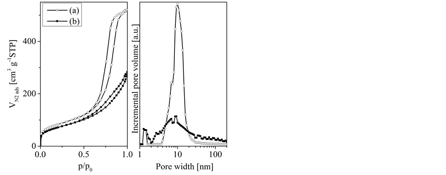
Figure 1. Nitrogen adsorption isotherms (left) and pore size distribution functions (density functional theorie, right) of the templates silica gel (a) and porous concrete (b).

Table 1. Textural data of used templates.
*Nitrogen adsorption, single point method; **Helium pycnometry.
starting pore volumes. This is necessary because of the volume shrinkage at higher temperatures. After placing the template sample into the reactor (vertical flow reactor) it was heated up to the desired temperature in a carrier gas stream (nitrogen, 2 Nl h−1). Then, the carrier gas stream was switched to pass a thermostated saturator containing the liquid precursor (n-hexane, 1-hexene from Sigma-Aldrich) and the carbon deposition started. The temperature of the saturator was adjusted to values which allow a precursor fraction of 15 mol% in the carrier gas stream. After defined periods (1 up to 150 hours) the carrier gas stream was switched back and the reactor was cooled down to ambient temperature whilst flowing through by the carrier gas. The mass gain of the template sphere caused by the carbon deposition was obtained by weighing. The carbon-template-composite sphere was then either placed back into the reactor to continue the carbon deposition or was treated with hydrofluoric acid (40 wt%, Sigma-Aldrich)to remove the template. The resulting carbon replicas were then thoroughly rinsed with water and dried.
2.3. Nitrogen Adsorption
Nitrogen adsorption and desorption isotherms were performed at 77 K on a Micromeritics ASAP 2020 volumetric adsorption system. The total surface area and the pore volume were determined applying the BET (Brunauer-Emmett-Teller) equation and the single point method, respectively. The pore size distribution (PSD) was obtained from the adsorption branch of the nitrogen adsorption isotherm applying the density functional theory. Nitrogen adsorption isotherms were measured from temperature pretreated template samples, carbon-template- composites, and carbon replicas, respectively.
2.4. X-Ray Tomography
X-ray tomography images were recorded on a homemade Micro-CT-equipment of the Fraunhofer IKTS-MD. The voxel size was about 10 µm3.
2.5. Helium Pycnometry
The skeleton volume of the sample monoliths was measured by helium pycnometry on a Porotec Pycnomatic ATC equipment. From that, the total pore volume was calculated by the difference between the geometric volume of the sample and the according skeleton volume.
3. Results and Discussions
3.1. Results
The carbon loading of porous concrete using n-hexane (1033 K, 13 h deposition time) was first observed by X-ray-tomography (Figure 2). The template (left hand side) is highly macroporous as indicated by the black areas of the image. This is important because from the image it can be concluded, that the template body is completely penetrated by macropores which could act as transport pores
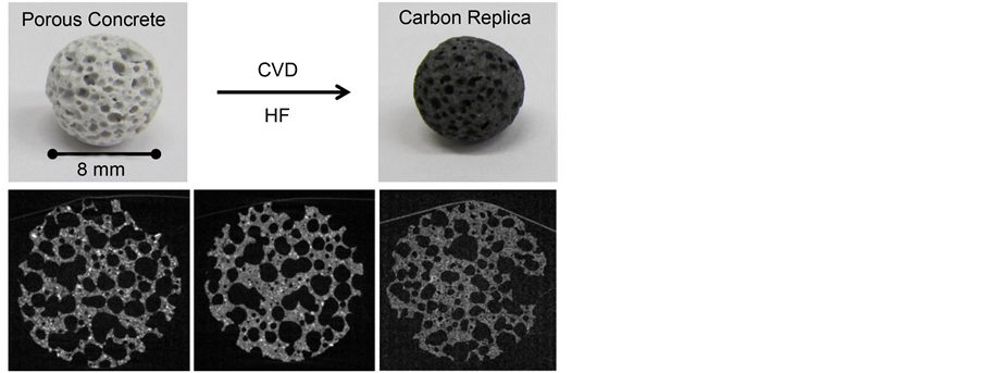
Figure 2. Photographs and X-ray-tomographical images, respectively of spheres of porous concrete (left hand side), carbon- porous concrete-composite (middle), and the carbon replica (right hand side); preparation conditions: n-hexane, 1033 K, 13 h deposition time.
for the carbon precursors.
The micro- and mesopores are located within the grey depicted framework of the material. The image of the carbon-template-composite (middle) is very similar to that of the template, which means no significant carbon deposition within the macropores is visible. So, under the applied reaction conditions (i.e. short deposition time) the carbon must preferably be located in the micro- and mesopores of the framework. This is in accordance with the observed ratio of the infiltrated carbon volume to the template pore volume obtained at the applied deposition time of 13 hours (Figure 3). As that ratio is about one a significant deposition outside of the template pores (i.e. the micro- and mesopores) seems to be less probable. The carbon replica (right hand side) is quite similar to its template in its appearance. There are macropores which should stem from the non filled macropores of the template. The carbon framework on the other hand was formed within the micro- and mesopores of the template framework and that is why the replica framework looks very alike to that of the template.
The time dependence of the carbon deposition has been observed on the basis of the ratio of infiltrated carbon volume to template pore volume. The volume of infiltrated carbon has been calculated by the mass gain assuming a skeleton carbon density of 2 g・cm−3. The single point volume obtained from the nitrogen adsorption isotherms has been used as the template pore volume because that volume comprises the micro- and mesopores. The carbon deposition mainly takes place in these pores as shown by x-ray tomography (Figure 2).
The development of these ratios with deposition time at different temperatures is shown in Figures 3-6, respectively.
On porous concrete, the conversion of n-hexane results in only a slight increase of the volume ratio at a reaction temperature of 883 K indicating a very low deposition rate (Figure 3). For the experiments at higher temperatures a
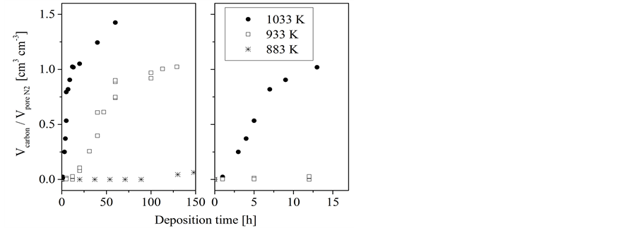
Figure 3. Conversion of n-hexane on porous concrete: dependence of the volume ratio of deposited carbon to the template pore volume on the deposition time at different temperatures.
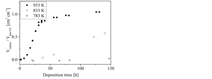
Figure 4. Conversion of 1-hexene on porous concrete: dependence of the volume ratio of deposited carbon to the template pore volume on the deposition time at different temperatures.
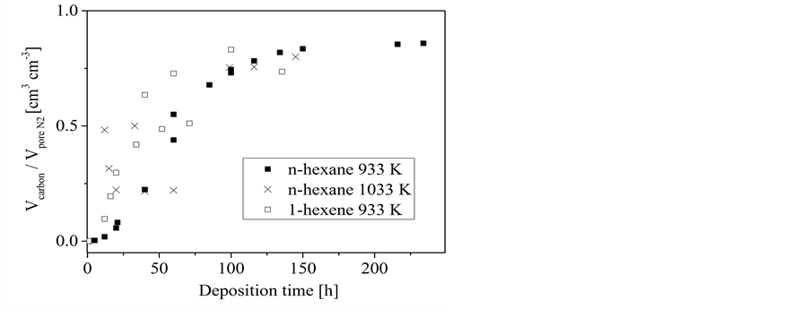
Figure 5. Conversion of n-hexane and 1-hexene, respectively, on silica gel: dependence of the volume ratio of deposited carbon to the template pore volume on the deposition time at different temperatures.
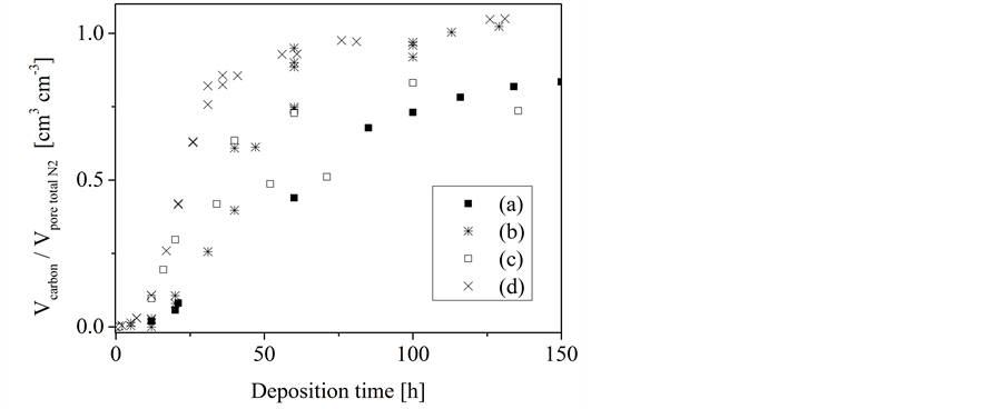
Figure 6. Dependence of the volume ratio of deposited carbon to the template pore volume on the deposition time at 933 K; precursor-template-systems: silica gel/n-hexane (a), porous concrete/n- hexane (b), silica gel/1-hexene (c), porous concrete/1-hexene (d).
three-stage developing of the volume ratio has been observed. After an initial period whereas no remarkable carbon loading is observed an almost linear rise follows. In dependence on the deposition temperature, the slope of that linear rise decreases after a certain deposition time to a different extent. While in case of the highest investigated temperature (1033 K) the slope decreases only moderately it levels down to a nearly plateau like course at the lower temperature of 933 K. Only at the highest temperature (1033 K) the volume of deposited carbon can exceed the template pore volume as it is indicated by the ratio Vcarbon/Vpore N2 which is larger one at longer deposition time (Figure 3). The length of the initial period and the linear rise as well depends on the reaction temperature-the lower the temperature the longer these individual periods. The carbon loading at the end of the first linear stage corresponds nearly to a complete filling of the template pores. Complete pore filling could not be achieved by using sucrose solution as the carbon precursor even when applying repeated loading cycles.
A similar pattern has been obtained for the conversion of 1-hexene on porous concrete (Figure 4). Also a three-stage developing of the volume ratio has been observed. However, the carbon deposition from 1-hexene occurs much faster as that from n-hexane. As for n-hexane a deposition was not found at temperatures below 883 K a significant deposition was obtained for 1-hexene at 833 K. Furthermore, the deposition from 1-hexene at 933 K proceeds similar to that from n-hexane at the considerably higher temperature of 1033 K, i.e. a three-stage course resulting in a nearly complete pore filling at about 50 hours.
For silica gel a somewhat different behavior has been found (Figure 5 and Figure 6). On the first glance, a three-stage-process of the carbon loading can at least be assumed. However, that effect is not as pronounced as it was found for porous concrete. The pore filling process finished at values clearly below those obtained for porous concrete (Figure 3). Furthermore, the carbon loading pro- cess occurs on silica gel quite independent of the used precursor and the temperature, respectively. This supports the assumption of a more complex carbon infiltration mechanism.
Nitrogen adsorption isotherms and according pore size distribution functions of carbon-porous concrete-composites obtained from n-hexane at 1033 K are shown in Figure 7. With increasing deposition time, i.e. increasing carbon loading the amount of adsorbed nitrogen decreases. In the same way, the calculated incremental pore volume derived from the pore size distribution functions decreases, too. However, the isotherm shape and consequently the maximum of the pore distribution function did not change the position with increasing carbon loading. This indicates that the template pore width is not affected by the deposited carbon.
For the deposition using n-hexane the decline of the free template volume was compared with the skeleton volume of the deposited carbon (Figure 8).
At the beginning of the procedure, the decline of the free template volume is somewhat larger than the volume of infiltrated carbon. This indicates a slight blocking of template pores (i.e. micro- and mesopores) by carbon. With increasing deposition time this difference decreases up to a crossing of the values. From that one can assume that either the blocking of pores disappears or the carbon loading in macropores becomes more significant. The latter mentioned effect would then overcompensate the effect of reduced carbon loading by blocked pores.
Nitrogen adsorption isotherms of selected carbon replicas are shown in Figure 9. The isotherms show a small increase in adsorption at low relative pressures indicating the existence of micropores. The corresponding values of the micropore volume are 0.06 and 0.18 cm3・g−1, respectively. These values are
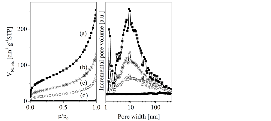
Figure 7. Nitrogen adsorption isotherms (left hand side) and according pore size distribution functions (right) of porous concrete (a) and carbon-porous concrete composite loaded at different periods: 3 hours (b), 5 hours (c), and 13 hours (d) with n-hexane at 1033 K.
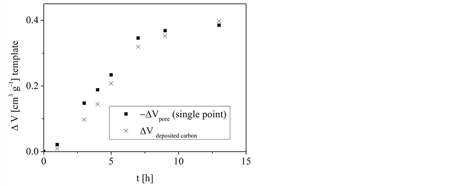
Figure 8. Conversion of n-hexane on porous concrete at 1033 K: dependence of the change of the free template pore volume (from Nitrogen adsorption at 77 K, according to the single point method) and the change of the volume of deposited carbon, respectively, on the deposition time.
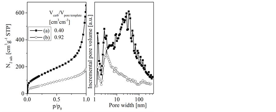
Figure 9. Nitrogen adsorption isotherms and pore size distribution functions for selected carbon replicas obtained from porous concrete template at different deposition times and temperatures: 933 K, 40 h (a), and 1033 K, 13 h (b); Vcarb/Vporetemplate indicates the ratio of deposited carbon volume to template pore volume, i.e. the apparent pore filling degree.
considerably lower than those obtained from sucrose derived carbons, even at similar carbon content of the loaded template (Table 2).
A continuous increase in adsorption follows over almost the whole pressure range indicating a broad size distribution of mesopores. The BET surface areas are in the range of about 200 up to about 480 m2・g−1. Furthermore it has to mention that all replicas possess a significant amount of macropores which cannot be detected by the nitrogen adsorption method (not shown here, [10] ). The template pore filling degree affects the porosity of the resulting replica: low pore
Table 2. Textural data of carbon replicas obtained by different template loading procedures.
*Dubinin-Raduskevich.
filling degree results in a replica with higher porosity. This is caused by the contribution of non-filled template pores to the replica porosity and the occurrence of carbon gasification reactions, respectively. Gasification reactions produce carbon micropores. However, with increasing amount of loaded carbon these micropores will be filled up and then finally disappear.
3.2. Discussions
The carbon deposition occurs mainly in the micro- and mesopores of the templates. Two different mechanisms of carbon deposition have to be considered. First, a steady covering of template pore walls by carbon. Second, a plug-like carbon growth starts from carbon seeds or some other kind of primary carbon species. A deposition according to the first model would result in a continuous constriction of the template pore diameters which should be visible in the pore size distribution functions obtained from the nitrogen adsorption experiments. That is, however, not the case. Furthermore, a constriction of the template pore width would lead to a steady decrease of the surface area on which carbon could be deposited. As a consequence, the mass gain caused by the carbon deposition would show a nonlinear time dependence which would not meet the experimental results. So, that model should be excluded.
Therefore, the second proposed model will be discussed. The initial period at the beginning of the deposition process can be explained by a mechanism similar to that of the formation of soot or carbon blacks [16] . During the diffusion in the narrow pores the precursor undergoes gas phase reactions which produce highly reactive carbon species. These species could act as seeds or as the here called primary carbon species for the subsequent occurring deposition. From the findings presented here it is not possible to derive whether these species are formed in the gas phase or on reactive sites of the pore walls or on both. In these pores, where a critical amount of these species is formed or where the species have grown to a critical size, respectively, the carbon deposition takes place starting from these primary species. The carbon deposition occurs on carbon surfaces considerably faster than on other substrates like the template pore walls. Therefore, a remarkable carbon deposition is observed only if that initial period has been passed. It produces a steadily growing carbon plug within the template pores whereas the carbon is deposited on the front faces of these plugs. As the area of these faces does not change the deposition rate remains constant which is indicated by the linear time dependence of the pore filling shown in Figure 3 and Figure 4, respectively. At the point when all pores are completely filled further carbon deposition can take place only in the template macropores or on the external surface. These processes are considerably slower by two reasons, namely the lower deposition rate on non-carbonaceous surfaces and the low surface area of the macropores and external surface, respectively.
According to that model, the degree of the template pore filling and consequently the quality of the carbon replica must depend on the location of the primary carbon species within the template particle. If they are located in the outer sphere of the template grain the growing carbon plug would block the pores and the inner sphere would remain empty. The porosity of the resulting replica would be considerably larger than it would be expected from the direct template effect [17] . At the same time, the mechanical stability of the replica grain or monolith, respectively, would be reduced.
On porous concrete that effect is not pronounced because the carbon loading finished nearly at the total pore filling. This is probably caused by the hierarchical arrangement of macropores and mesopores which allows an almost non-restricted mass transport. However, in silica gel such an arrangement does not exist. The maximum pore filling degree is about 20% smaller and it has to assume, that mass transport affects the carbon deposition considerably. This conclusion is furthermore supported by the fact:
- that the time dependence of the carbon deposition in silica gel is almost not affected by the temperature and the used precursor, respectively (Figure 5),
- the three-stage-course of the deposition is not as pronounced as it is found for porous concrete.
Furthermore, to obtain an optimal material regarding mechanical stability and porosity an optimal balance of the carbon deposition in the micro- and mesopores on the one hand and in the macropores on the other hand has to be found. Carbon deposition in the macropores is expected to enhance the stability of the whole carbon monolith but would reduce the overall porosity.
4. Conclusions
Applying the CVD-method, a high degree of template-carbon-loading could be achieved. The formation of micropores was considerably suppressed. The carbon deposition occurs according to a three-stage process. In an initial period, primary carbon species were formed. On these species, the carbon deposition then starts and carbon plugs grow within the template pores. The carbon growth occurs from the inner to the outer sphere. There is no proof of a remarkable covering by carbon of the pore walls of the micropores and mesopores, respectively. However, slow carbon deposition on the walls of the porous concrete macropores takes place, which affects the overall porosity of the replicas in different ways. In difference to silica gel, mass transport effects do not limit the carbon deposition in porous concrete significantly because the body of that template is penetrated by macropores.
The materials could be used in applications in which porous monoliths are flown through by liquids. For that, the mechanical stability and permeability, respectively, are key factors which determine the quality of the material. As both features depend on the monolith porosity, further investigation of their interplay with each other is suggested. This comprises e.g. the further optimization of the balance of the carbon deposition in the different template pores by the variation of the deposition temperature and the selection of the carbon precursor, respectively.
Acknowledgements
O. K. thanks to the German Research Foundation (DFG; Grant Nr. KL 1202/10- 1), the European Regional Development Fund (EFRE, Brandenburg, Proj. HL 23048413), and to the Brandenburg University of Technology Cottbus-Senften- berg for granting a research professorship. Thanks to L. Wilk for technical support and M. Taubert for discussion.
Cite this paper
Klepel, O., Danne- berg, N., Suckow, M. and Erlitz, M. (2017) Carbon Replicas of Porous Concrete Obtained by Chemical Vapor Deposition― Some Aspects of the Synthesis Mechanism. Materials Sciences and Applications, 8, 614- 627. https://doi.org/10.4236/msa.2017.88043
References
- 1. Knox, J.H. and Kaur, B. (1986) Structure and Performance of Porous Graphitic Carbon in Liquid Chromatography. Journal of Chromatography A, 352, 3-25.
https://doi.org/10.1016/S0021-9673(01)83368-9 - 2. Sonobe, N., Kyotani, T. and Tomita, A. (1990) Carbonization of Polyfurfuryl Alcohol and Polyvinyl Acetate between the Lamellae of Montmorillonite. Carbon, 28, 483-488.
https://doi.org/10.1016/0008-6223(90)90042-W - 3. Kyotani, T., Nagai, T., Inoue, S. and Tomita, A. (1997) Formation of New Type of Porous Carbon by Carbonization in Zeolite Nanochannels. Chemistry of Materials, 9, 609-615.
https://doi.org/10.1021/cm960430h - 4. Parmentier, J., Saadhallah, S., Reda, M., Gibot, P., Roux, M., Vidal, L.,Vix-Guterl, C. and Patarin, J. (2004) New Carbons with Controlled Nanoporosity Obtained by Nanocasting Using a SBA-15 Mesoporous Silica Host Matrix and Different Preparation Routes. Journal of Physics and Chemistry of Solids, 65, 139-146.
https://doi.org/10.1016/j.jpcs.2003.10.008 - 5. Ma, Z., Kyotani, T. and Tomita, A. (2002) Synthesis Methods for Preparing Microporous Carbons with a Structural Regularity of Zeolite Y. Carbon, 40, 2367-2374.
https://doi.org/10.1016/S0008-6223(02)00120-3 - 6. Ryoo, R., Joo, S.H. and Jun, S. (1999) Synthesis of Highly Ordered Carbon Molecular Sieves via Template-Mediated Structural Transformation. Journal of Physical Chemistry B, 103, 7743-7746.
https://doi.org/10.1021/jp991673a - 7. Lu, A.H. and Schüth, F. (2006) Nanocasting: A Versatile Strategy for Creating Nanostructured Porous Materials. Advanced Materials, 18, 1793-1805.
https://doi.org/10.1002/adma.200600148 - 8. Scholz, K., Scholz, J., McQuillan, A.J., Wagner, G. and Klepel, O. (2010) Partially Embedded Highly Dispersed Pt Nanoparticles in Mesoporous Carbon with Enhanced Leaching Stability. Carbon, 48, 1788-1798.
https://doi.org/10.1016/j.carbon.2010.01.021 - 9. Günther, D., Beckmann, J., Schoneich, M., Schmidt, P. and Klepel, O. (2012) Porous Concrete as a Template for the Synthesis of Porous Carbon Materials. Carbon, 50, 3096-3098.
https://doi.org/10.1016/j.carbon.2012.02.039 - 10. Taubert, M., Beckmann, J., Lange, A., Enke, D. and Klepel, O. (2014) Attempts to Design Porous Carbon Monoliths Using Porous Concrete as a Template. Microporous Mesoporous Materials, 197, 58-62.
https://doi.org/10.1016/j.micromeso.2014.06.005 - 11. Klepel, O., Danneberg, N., Drager, M., Erlitz, M. and Taubert, M. (2016) Synthesis of Porous Carbon Monoliths Using Hard Templates. Materials, 9, 214.
https://doi.org/10.3390/ma9030214 - 12. Delhaes, P. (2002) Chemical Vapor Deposition and Infiltration Processes of Carbon Materials. Carbon, 40, 641-651. https://doi.org/10.1016/S0008-6223(01)00195-6
- 13. Zhang, W. and Hüttinger, K.J. (2001) Chemical Vapor Infiltration of Carbon—Revised: Part I: Model Simulations. Carbon, 39, 1013-1022.
https://doi.org/10.1016/S0008-6223(00)00214-1 - 14. Norinaga, K. and Deutschmann, O. (2007) Detailed Kinetic Modeling of Gas-Phase Reactions in the Chemical Vapor Deposition of Carbon from Light Hydrocarbons. Industrial & Engineering Chemistry Research, 46, 3547-3557.
https://doi.org/10.1021/ie061207p - 15. Li, A. and Deutschmann, O. (2007) Transient Modeling of Chemical Vapor Infiltration of Methane Using Multi-Step Reaction and Deposition Models. Chemical Engineering Science, 62, 4976-4982. https://doi.org/10.1016/j.ces.2007.01.069
- 16. Inagaki, M. and Kang, F. (2014) Materials Science and Engineering of Carbon: Fundamentals. 2nd Edition, Butterworth-Heinemann, Elsevier, Oxford.
- 17. Klepel, O., Erlitz, M., Garsuch, A., Scholz, K., Suckow, M., Taubert, M. and Utgenannt, S. (2016) Template Assisted Synthesis of Porous Carbons Revisited—Where Does the Porosity Come from? Microporous Mesoporous Materials, 224, 163-167.
https://doi.org/10.1016/j.micromeso.2015.11.047