Materials Sciences and Applications
Vol.07 No.09(2016), Article ID:70283,19 pages
10.4236/msa.2016.79041
Electrical, Thermal and Mechanical Properties of CNT Treated Prepreg CFRP Composites
Yelda Akcin1, Sukru Karakaya2, Omer Soykasap3
1Faculty of Technology, Metallurgy and Materials Engineering, Afyon Kocatepe University, Afyonkarahisar, Turkey
2Faculty of Technology, Mechanical Engineering, Afyon Kocatepe University, Afyonkarahisar, Turkey
3Faculty of Engineering, Materials Science and Engineering, Afyon Kocatepe University, Afyonkarahisar, Turkey

Copyright © 2016 by authors and Scientific Research Publishing Inc.
This work is licensed under the Creative Commons Attribution International License (CC BY 4.0).
http://creativecommons.org/licenses/by/4.0/


Received: July 28, 2016; Accepted: August 28, 2016; Published: September 1, 2016
ABSTRACT
This study is part of Smart Intelligent Aircraft Structures (SARISTU) project, which aims considerable improvements in aircraft damage tolerance, electrical conductivity and weight reduction besides producibility in industrial scale. In this study, the effect of multiwalled carbon nanotube reinforcement on electrical, thermal and mechanical properties of T800/M21 carbon fibre reinforced plastic is studied experimentally. T800/M21 is a commercial prepreg carbon fibre/epoxy composite material considered for CNT treatment by means of CNT-doped thermoplastic-based dry powder. The CNTs are deposited on top of prepreg material uniformly using a controlled spraying machine selecting the best state-of-the art and innovative performing technology from the candidate technologies within the project. The electrical conductivity of the composite material with/without CNT is measured in longitudinal, transverse and thickness directions. The changes occurring in the electrical conductivity of the composite materials are investigated. In order to investigate thermal behaviour of the composite materials, differential scanning calorimetry and thermogravimetric analyses are performed. Detailed thermal analysis is conducted for with/without carbon nanotube reinforced material to obtain the thermal conductivity, specific heat and thermal expansion coefficient of the material. Finally, the effect of carbon nanotube reinforcement on mechanical behaviours is studied by tensile, bending and shear tests.
Keywords:
Carbon Nanotubes, Electrical Properties, Thermal Properties, Mechanical Properties, CFRP

1. Introduction
Fibre reinforced polymer composite (CFRP) materials provide a significant mass saving in production due to their high strength/mass and high stiffness/mass ratios compared with metals. Lighter aircraft with multifunctional materials such as carbon nanotube (CNT) doped CFRP provides energy and performance efficiency; hence research on implementation of CNT doping on commercially available CFRP composites in the aerospace industry has focused on easy and environment-friendly production in an industrial scale in recent years [1] . CNT has extraordinary electrical, thermal and mechanical properties making them potentially attractive materials for use in aerospace structures in order to enhance the material properties. Epoxy polymers are the most commonly used matrix because of their mechanical properties along with their compatibility with a large variety of fibres. This material ensures superior properties of high modulus, high thermal and chemical resistance, and low creep for most aircraft structural applications. However, epoxy resin is brittle and allows the formation of cracks between fibre and matrix in the composite material subject to certain loading conditions [2] , especially during liquid moulding process due to viscosity of epoxy [1] .
Electrical conductivity of epoxy is very low and even if it is used as a matrix for conductive carbon fibre, the produced CFRP composite material cannot reach required electrical conductivity for electrical structure network of airframes to prevent failure especially in thickness direction [3] . The electrical functions of airframes such as electro static discharge, electrical bond, electromagnetic shielding, and lightning strike protection are closely associated with electrical conductivity of the materials. For example, a possible structural and electronic damage may occur due to lightning strike when the airframe is not conductive enough. In order to protect CFRP structures of aircraft, the current state of the art metal wire mesh or expanded aluminium and copper materials are incorporated into the surface of these composite structures so that the lightning strike energy is dissipated over the surface and hence it prevents damage of the composite material beneath. On the other hand, adding mass increases the weight of aircraft structures which degrades performance efficiency of the aircraft. If a conductive material can be produced directly without the need of coating the surface after production, the installation cost of electrical structure network decreases. In literature, there are many studies on enhancing the electrical conductivity and mechanical properties of epoxy by adding fillers such as short carbon fibre, carbon nanofiber, carbon nanotube, etc. As a common result of these studies, all the fillers improve the electrical conductivity and mechanical behaviours of epoxy [4] - [8] .
In recent years, CNTs are considered the most popular materials as fillers for CFRP materials. Because, they have high potential to improve electrical conductivity, mechanical and thermal properties of polymer material simultaneously without causing to weight increment [9] . To improve damage tolerance of composite materials, the usage of thermoplastic veils as interleaf materials and thermoplastic carriers for implication of nanoparticles are preferred methods. It has been reported that remarkable improvements are obtained in the fracture toughness of composite materials produced with these methods [10] [11] .
The thermal behaviours of polymer used in CFRP are as important as mechanical and electrical properties since aircraft structures are exposed to thermal loads as well. Resin melting, vaporization and ply delamination may occur due to the poor thermal conductivity or electrical resistance of composite materials during lightning strike or electrical discharge. The studies on the effect of CNT doping on thermal conductivity exhibit that CNT doping produces slight enhancement in the thermal conductivity as opposite to electrical conductivity [12] [13] . According to many studies on CNT doped CFRP composites, it is seen that the improvement and good performance is related to dispersion of CNT in the matrix which is the main issue of the manufacture method used [14] - [17] .
Production of CNT doped carbon fibre/epoxy composite with conventional liquid injection technologies causes some problems. During doping proses, CNTs are mixed and interact with the resin, causing an increase its viscosity. High viscosity obstructs the flow of the resin and resin impregnation of fibres decreases accordingly. The viscosity can be reduced by increasing the process temperatures but in this case CNTs show tendency to agglomerate. On the other hand, the CNTs collected around the carbon fibres during the infusion process can lead to formation of deflective layers [1] . CNTs with good distribution in the matrix improve many properties of CFRP composite materials without increasing structural weight whereas they cause degradation of electrical conductivity, mechanical and thermal behaviours when they are agglomerated. This study is as part of Smart Intelligent Aircraft Structures (SARISTU) project, which aims considerable improvements in aircraft damage tolerance, electrical conductivity and weight reduction. Several state-of-the art and innovative solutions such as CNT doped veil, CNT doped binder, CNT treated prepreg etc. were studied within SARISTU to enhance the damage tolerance and electrical conductivity of composite materials. Besides these aims, producibility of composite material in industrial scale was taken in consideration as an important effect. As the results of studies, the two best performing technologies, 1) thermoplastic veils and 2) CNT treated prepreg with spraying method are selected to transfer from the laboratory scale to demonstrator production and accordingly to be studied at an industrial scale. For inclusion of CNT to CFRP composite, production with the thermoplastic veil is suitable for liquid composite moulding while the spraying method is suitable for prepreg [1] . In this study, the effect of CNT addition with spraying method on electrical, mechanical and thermal behaviour of unidirectional carbon fibre/epoxy prepreg composite material is investigated experimentally. T800/M21 is a commercial prepreg carbon fibre/epoxy composite material, which is considered CNT treatment by means of CNT-doped thermoplastic-based dry powder. For the production of CNT doped carbon fibre/epoxy composite materials, powder deposition is used to enable production on an industrial scale and resolves agglomeration problems during doping. Section 2 describes the experiments of thermal, mechanical and electrical studies. The electrical conductivity of neat and CNT doped composite material is determined at room temperature in longitudinal, transverse, and thickness directions. Moreover, the electrical conductivity is analysed at lower and higher temperatures in the thickness direction. For the thermal behaviour, Differential Scanning Calorimetry (DSC) and Thermogravimetric (TG) analyses are performed for the measurements of specific heat capacity, coefficient of thermal conductivity and coefficient of thermal expansion. Mechanical behaviour of CNT doped material is investigated by tensile, three point bending and shear tests. Next the experimental results are discussed in Section 3. Main conclusions of the paper are presented in the final section.
2. Experimental Studies
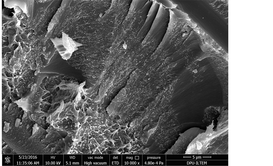
The neat material used in the study is T800/M21 carbon fibre/epoxy prepreg, which is commercially available, aerospace qualified unidirectional material with an areal density of 198 g/m2. Production of CNT-treated CFRP prepreg and curing the CFRP material for the specimens are carried out by the project partners as described in what follows. The NC7000 multi walled carbon nanotube (MWCNT) is produced by catalytic chemical vapour decomposition by the project partner Nanocyl SA, Belgium. MWCNT NC7000 has the following properties: an average diameter of 9.5 nm, an average length of 1.5 µm, carbon purity of 90%, metal oxide of 10%, surface area of 250 - 300 m2/g. Nanocyl aimed at preventing agglomeration of CNTs when added to resin and manufacturing ease for prepreg materials, and achieved a good dispersion of CNTs in thermoplastics to produce compound PLASTICYLTM using industrial twin-screw extruder in pellet form. These pellets can be produced via a wide range of thermoplastic resin. For this study, they are produced from Griltex D1330A Polyamide. The reason of selecting polyamide resin is its melting temperature ranging between 125˚C - 135˚C in order to melt the polyamide resin during the curing cycle and to migrate in CFRP. CNT doped prepreg materials are produced by the other project partner University of Patras, Greece. CNT-doped thermoplastic granules are ground into powder grain size in the range 100 to 250 µm. Then, these powders are deposited on top of T800/M21 carbon/epoxy prepreg material as 2 g/m2 in a controlled spray machine developed specifically for this purpose. The process is customized to deliver nano-treated prepregs and prevents the formation of agglomeration. Finally both neat and CNT doped T800/M21 carbon fibre/epoxy prepreg materials are supplied and laminates are produced by the other project partner Turkish Aerospace Industries Inc., Turkey. The materials are cured by autoclave with curing cycle of 2 hours under 8 bar pressure at 180˚C temperature, next cut into required specimen sizes. Optic microscope and scanning electron microscope (SEM) images taken from the cross sections of the specimens are given in Figures 1-3 for both neat and CNT doped composite material. It is seen that there is no agglomeration of CNTs, which are dispersed uniformly in epoxy resin. The spraying method ensures a good dispersion and manufacture ease. Thermal, mechanical and electrical conductivity tests are described in the following subsections.
2.1. Thermal Tests
Thermal behaviour of the materials is investigated by several analyses and measurements
 (a)
(a)
 (b)
(b)
Figure 1.SEM images of the material. (a) Neat carbon/epoxy composite specimen; (b) CNT doped carbon/epoxy composite specimen.
including DSC, TG, specific heat capacity, thermal conductivity, and thermal expansion. Coefficient of thermal conductivity of neat and doped specimens is determined at
 (a)
(a)
 (b)
(b)
Figure 2. High-magnification images of CNT doped carbon/epoxy composite specimen. (a) 25,000×; (b) 10,000×.
the room temperature in the longitudinal, transverse and thickness direction with C-THERM/TCi thermal conductivity device. Surface of specimens with dimensions of

Figure 3. Optic microscope images of the material taken from (a) a longitudinal section, (b) a transverse section.
50 × 50 × 4 mm (length × width × thickness) is prepared by sanding before the measurement. Next, DSC, TG and specific heat capacity analyses are performed with NETZSCH Differential Scanning Calorimetry. The specimens with dimensions of 5 × 5 × 4 mm (length × width × thickness) are tested at the temperatures from 24˚C to 110˚C with a heating rate of 20˚C/min at atmospheric conditions. Finally, to determine the dimensional changes of the composite materials due to temperature effect, the coefficient of thermal expansion of 25 × 5 × 4 mm (length × width × thickness) specimens is measured in the longitudinal and transverse directions with NETZSCH 402 CD Dilatometer between 30˚C and 180˚C.
2.2. Mechanical Tests
The mechanical properties of neat and doped T800/M21 carbon/epoxy specimens are investigated via tensile, bending and shear tests. First, the tensile tests are performed with Instron 8801 tensile testing machine with video extensometer. The tensile tests are performed according to ASTM D 3039M standard in the longitudinal and transverse directions. The specimens with a dimension of 250 × 20 × 2 mm (length × width × thickness) are prepared with layups (0)n, (90)n. The metal tabs are affixed at the end of the specimens to prevent premature failure; and the tests are carried out with a speed of 2 mm/min. Tensile strength, elastic modulus, Poisson’s ratio and failure strain are obtained as results of tensile tests. Next, three point bending tests are applied to neat and doped specimens according to ASTM D790 standard. The specimens with dimensions of 120 × 10 × 2 mm (length × width × thickness) are tested with a head speed of 5 mm/min. The bending modulus of specimens is obtained. Last, the shear tests are performed according to ASTM D3518 standard to obtain shear modulus of specimens. For these tests, the specimens with dimensions of 100 × 25 × 2 mm (length × width × thickness) and layup (±45)n are prepared and the tensile test is performed. For all mechanical tests, six specimens are prepared and tested and then average is taken.
2.3. Electrical Conductivity Tests
A test apparatus is established to measure electrical conductivity of specimens at room temperature. The schematic view of established test apparatus is given in Figure 4. There are two Teflon parts mounted on a rod and two copper parts mounted on the Teflon parts for the testing apparatus. One of the Teflon parts is fixed whereas the other is movable horizontally so that the measurement length is adjustable. The apparatus allows the measurement of electrical conductivity of specimens in longitudinal, transverse and thickness directions. In order to reduce the contact resistance between the specimen and the probes, the surface of specimens are coated with silver paint, and the measurements are performed with four-probe-method in order to eliminate any inference of probe resistance [18] . First, the specimens are placed between the copper plates, and full contact is ensured by applying force, then the electrical conductivity of specimens is measured with HM8118 LCR-Bridge at room temperature. Three neat and doped specimens are prepared for each direction, the measurements are repeated five times and the results are averaged. In order to further investigate the change of electrical conductivity with temperature in the thickness direction, the electrical conductivity of neat and CNT doped materials are measured with Novacontrol Concept 50 Dielectric and Impedance Spectrometer at 1 kHz frequency and between the temperatures −100˚C and 160˚C.
3. Results
3.1. Thermal Tests
The thermal conductivity of neat and doped specimens is measured in longitudinal, transverse and through the thickness and the results are given in Table 1. The thermal conductivity of the doped specimens decreases slightly in all directions. While the coefficient of thermal conductivity of specimens in longitudinal is very high, it is relatively lower in the transverse and thickness direction. According to quantum mechanics,

Figure 4. Test apparatus to determine the electrical conductivity of specimens at the room temperature.

Table 1. Thermal conductivity of neat and CNT treated T800/M21.
thermal conduction in carbon materials is carried by phonons in which the atoms or molecules uniformly oscillates with vibration modes. Although CNTs have high thermal conductivity, and hence it was expected a higher thermal conductivity due to CNT treatment according to the rule of mixtures, there is a decrease in the thermal conductivity in three directions due to CNT treatment. However thermal conduction is significantly affected by scattering any structural defects, discontinuities, and layer interactions. According to the studies, discontinuities in polymer lead to reduction of mean free oscillation of polymer molecules and electron scattering [19] . So, it is concluded that CNT treatment does not increase conduction of the carbon fibre/epoxy system. The thermal conductance and electrical resistance can cause resin melting, vaporization and ply delamination, reduction of thermal conductivity is a preferred feature for carbon fibre/polymer composites [20] .
DSC diagrams of the neat and CNT doped specimen are given in Figure 5 and Figure 6, respectively. The Figure 6 is zoomed partition of Figure 5 in order to see the glass transition temperature closely. The first peak is seen around 200˚C and this corresponds to the glass transition temperature. After this temperature, the system shows two exothermic reactions with heat output during which degradation reactions of epoxy matrix occur. First peak indicates the decomposition of lower molecular weight components that have thermally weak bonds and the other one is the degradation of higher molecular weight components formed during curing as discussed in the references [21] - [24] . The phase changes of the neat and doped materials are similar according to the diagrams. The phase change temperatures are compared in Table 2 in more details, in which Tonset is the starting temperature of reaction; Tg is glass transition temperature; Tfinish is the finishing temperature of reaction and Tp is peak point of the reaction. While the glass transition temperature of neat specimen is 207˚C, the glass transition temperature of CNT doped specimen is 212˚C with a 5˚C increment. The same increment is also seen in the decomposition reactions for CNT doped specimen. According to the studies on polymeric materials, addition of filler materials may prevent movement of the molecules and diffusion; thereby this situation leads to an increase in the glass transition and decomposition temperatures as discussed in the references [19] [25] [26] .
The peaks labelled as the glass transition temperature and the decomposition reaction in DSC diagrams is also confirmed with TG analyses in Figures 7-9. Figure 7 and Figure 8 show the combination of DSC and TG curves, the first degradation reaction in DSC diagrams shows itself with a sudden mass loss approximately between 250˚C - 450˚C and the second degradation reaction starts after 450˚C in the TG diagrams.

Figure 5. DSC thermograms of neat and CNT doped T800/M21.

Figure 6. Glass transition temperatures of neat and CNT doped T800/M21.
Table 2. DSC results of neat T800/M21 and CNT doped T800/M21.
When the TG diagrams of neat and CNT doped specimens are compared, the mass losses are quite close for both specimens until the start of first degradation reaction as seen in Figure 9. When the degradations begin, more mass loss observed in CNT

Figure 7. TG thermograms of neat T800/M21.
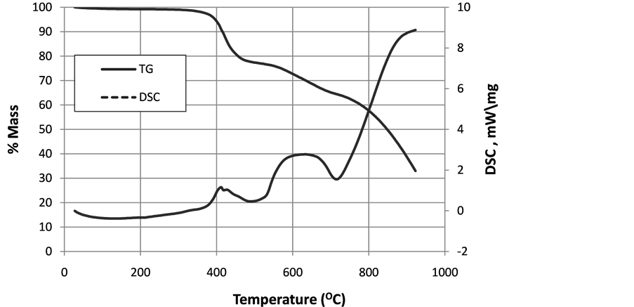
Figure 8. TG thermograms of CNT doped T800/M21.
doped specimens than the neat specimens (41% mass loss in neat specimens whereas 48% mass loss in doped specimens at 830˚C). More mass loss is seen in CNT doped specimens because CNTs combust around 600˚C in air and get away from system at atmospheric conditions according to the studies [27] [28] .
The specific heat capacity increases with temperature for both neat and doped specimens as given in Figure 10. However, the value of the doped specimens is always lower than that of the neat specimens. The specific heat capacity is obtained as 0.86 J/gK for the neat material and 0.80 J/gK for CNT doped material with a 7% reduction under constant pressure at 50˚C. The specific heat capacity is described as the amount

Figure 9. Comparative TG thermograms of neat and CNT doped T800/M21.

Figure 10. Specific heat capacity of neat T800/M21 and CNT doped T800/M21 specimens.
of heat necessary to raise the temperature of a certain mass by 1 degree Kelvin. If evaluated in atomic size, heat capacity is stored energy as atomic vibrations in materials. Depending on this, CNTs situated in the epoxy hinder the movement of polymer molecules and cause a decrease in total kinetic (thermal) energy of the system. Thus, the specific heat capacity of CNT doped specimens is lower than that of the neat specimens.
The coefficient of thermal expansion (CTE) is an important property for polymers used in engineering applications. For good dimensional stability, a low CTE is demanded. Aerospace industry is a pioneer in the use of composite materials comprised of fibres with a low CTE and resin with high CTE. The aim is to reduce the total thermal deformation for good thermal stability [29] . The CTE of M21 epoxy matrix is 55 × 10−6/˚C whereas CTE of T800 carbon fibre is −0.56 × 10⁻⁶/˚C [30] [31] . During heating, the matrix tends to expand whereas the carbon fibre tends to shrink with increasing temperature. According to Figure 11, the CTE of neat T800/M21 composite material is positive and low in longitudinal direction over the range of 20˚C and 180˚C. On the other hand, CTE of CNT doped material is almost zero, negative up to 140˚C and lower in magnitude than that of the neat material. Behaviour of the carbon fibre dominates the expansion in longitudinal direction. Further obstructive effect of CNTs on polymer chains possibly leads to negative effect on expansion of epoxy in CNT doped system, and the composite material is shrunken with a reduction of the CTE. On the other hand, the matrix plays an important role in transverse direction for CTE. CTEs are higher in transverse direction compared to the longitudinal direction as expected. The measured CTEs of the specimens increase with the temperature between 30˚C and 180˚C as given in Figure 12. CNT doped specimens are expanded more than the neat specimens in transverse direction, the effect is much more significant at lower temperatures. In literature, there are some studies showing that addition of CNT in polymer matrix causes an increase in stability [32] [33] . Even if the result for the longitudinal direction support this studies, the same effect is not seen in transverse direction. It is thought that this situation is related to the production method and weight percentage of the CNTs.
3.2. Mechanical Tests
The tensile strength, elastic modulus, Poisson’s ratio and failure strain are measured in fibre and transverse directions. The results are summarized in Table 3 for the neat and in Table 4 for CNT doped materials. In the tables, w denotes the specimen width, t denotes the specimen thickness, and E denotes the elastic modulus of specimens.
According to Table 3 and Table 4, addition of CNT in carbon/epoxy composite system increases the tensile strength by 7%, the elastic modulus by 4%, and the failure strain by 16% in the longitudinal direction. In the transverse direction, the tensile strength increases by 21%, the elastic modulus increases by 21% and the failure strain increases by 9%. CNTs show the greatest effect on the failure strain in longitudinal direction and on the tensile strength in transverse direction.

Figure 11. CTE of neat and CNT doped T800/M21 specimens in the longitudinal direction.
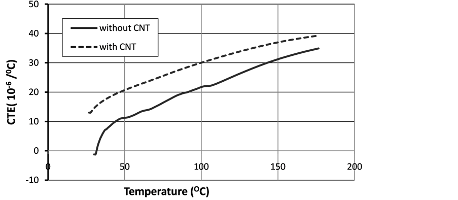
Figure 12. CTE of neat and CNT doped T800/M21 specimens in the transverse direction.
Table 3. Tensile test results of neat T800/M21.
Table 4. Tensile test results of CNT doped T800/M21.
The three point bending test is applied to determine the effect of CNT treatment on the flexural properties of carbon/epoxy specimens. The obtained results for the neat and doped specimens are given in Table 5, where s is the distance between supports, Ef is bending modulus. The addition of CNTs increases the bending modulus by 11% approximately for both fibre and transverse directions.
The shear test is performed to obtain shear modulus, G12. The test results are given in Table 6 for both materials. According to the results, the shear modulus increases by 12% in the carbon/epoxy system with CNT addition.
Considering all the mechanical test results, CNT addition improves all mechanical properties. In fibre/epoxy composite systems, fibre-matrix interface is one of the most important resources that cause crack initiation during loading, because the formation of cracks starts in the fibre-matrix interface generally. Presence of CNTs in carbon/ epoxy composite material prevents the formation and propagation of the cracks by affecting load distribution. Thus, it improves the mechanical properties of carbon/epoxy composite materials as discussed in the references [14] [15] . It should be noted that the studies realized within project of SARISTU to improve the damage tolerance of carbon fibre/epoxy composite materials show that, fracture toughness for mode I, (Gic) of
Table 5. Bending test results of neat and CNT doped T800/M21 specimens.
Table 6. Shear test results of neat and CNT doped T800/M21 specimens.
CNT treated T800/M21 specimen is %43 higher than untreated samples [34] .
3.3. Electrical Conductivity
The results of test performed in room temperature are presented in Table 7. Addition of CNT increased the electrical conductivity of the carbon/epoxy composite significantly in fibre and thickness direction. This increment is 59% in longitudinal direction and 92% in thickness direction. However, the increase in transverse direction is only 10% which is less than the other directions.
In Figure 13, the effect of temperature on electrical conductivity in thickness direction is given for the temperature range of −100˚C and 160˚C at 1 kHz frequency. According to results, the effect of temperature on electrical conductivity of neat specimens is negligible for the temperature range considered. On the other hand, the electrical conductivity increases after 100˚C in CNT doped specimens significantly. Increased electrical conductivity through the thickness at high temperatures is a desirable property for lightning strike protection of aircraft structures because a sudden rise of temperature is observed at the region where the lightning hits the surface when the electrical conductivity of the material is lower. Increased electrical conductivity at elevated temperatures will further reduce the structural damage.
4. Conclusions
The thermal, mechanical and electrical behaviours of CNT doped unidirectional T800/ M21 carbon fibre/epoxy prepreg composite material are obtained by experimental studies. CNT-doped thermoplastic-based dry powder was deposited uniformly on top of prepreg material for the treatment and it increases material mass by only 1%.
In order to investigate thermal behaviour of the composite materials, differential scanning calorimetry and thermogravimetric analyses are performed to the specimens. Later, detailed thermal analysis is conducted for with/without carbon nanotube reinforced material to obtain the thermal conductivity, specific heat and thermal expansion coefficient of the material. According to the results, it is seen that the CNT reinforcement has both positive and negative effects on the thermal properties. 1) CNT addition reduces the thermal conductivity in three directions slightly whereas the glass transition
Table 7. Electrical conductivity of neat and CNT doped T800/M21 specimens at room temperature.

Figure 13. Temperature effect on electrical conductivity of neat and CNT doped T800/M21 specimens in thickness direction.
and decomposition temperature increase by 5˚C, which extends the upper service temperature limit of the material. The reduction of thermal conductivity is negligible in longitudinal and thickness directions whereas 12% in transverse direction. With the supporting evidence in the literature, it is concluded that the presence of CNTs in the epoxy matrix causes discontinuities in polymer leading to reduction of mean free oscillation of polymer molecules and electron scattering and in turn decreasing the thermal conductivity. On the other hand, presence of CNTs in epoxy matrix prevents movement of polymer molecules and diffusion. Thus, it leads to an increase in the glass transition and decomposition temperatures. 2) The specific heat capacity of CNT doped material decreases with the temperature by 7% compared to that of neat material. Because, CNTs situated in the epoxy hinder the movement of polymer molecules and cause a decrease in total kinetic (thermal) energy of the system. 3) CNT addition causes a decrease in expansion of specimen compared to the neat material in longitudinal direction which is considered as a positive effect for thermal stability of the material. On the other hand, the coefficient of thermal expansion of the doped specimen is significantly higher than the neat specimen in transverse direction. The effect is less significant at elevated temperatures.
The effect of carbon nanotube reinforcement on mechanical behaviour is studied by tensile, bending and shear tests. The results show that the addition of multi-walled carbon nanotubes to the CFRP improves all mechanical properties because it prevents the formation and propagation of cracks that affect load distribution significantly. CNTs show the greatest effect in the failure strain in longitudinal direction and in the tensile strength in transverse direction. Addition of CNT in carbon/epoxy composite system increases the tensile strength by 7%, the elastic modulus by 4%, and the failure strain by 16% in the longitudinal direction. In the transverse direction, the tensile strength increases by 21%, the elastic modulus increases by 21% and the failure strain increases by 9%. The addition of CNTs also increases the bending modulus by 11% for both fibre and transverse directions.
It is found that the addition of carbon nanotube increases the electrical conductivity in all directions. In CNT doped specimens, electrical conductivity of the carbon/epoxy composite increases significantly in longitudinal direction by 59% and thickness direction 92% whereas less increase of 10% is observed in transverse direction. The electrical conductivity increases after 100˚C for the doped material in thickness direction, which is desirable property for aircraft structures subject to lightning strike in order to reduce the corresponding damage area further. According to the studies in SARISTU, micro- and nanoparticle addition has been successfully used to improve the potential discharge time and to allow otherwise isolating components to perform low-level electrical tasks. CNTs with high aspect ratio particles reduced the required filler content for electrical percolation. Therefore it is beneficial to include CNT in CFRP to reduce the number and size of electrical structural network components. Requirements for lightning strike direct effects are difficult to achieve with CNT doped prepreg to provide a stand-alone solution for electrical conductivity. However, they can help to reduce material damage.
Acknowledgements
SARISTU project has received funding from the European Union’s Seventh Framework Programme for research; technological development and demonstration under grant agreement no 284562.
Cite this paper
Akcin, Y., Karakaya, S. and Soykasap, O. (2016) Electrical, Thermal and Mechanical Properties of CNT Treated Prepreg CFRP Composites. Materials Sciences and Applications, 7, 465-483. http://dx.doi.org/10.4236/msa.2016.79041
References
- 1. Yu, H., Lu, C., Xi, T., Luo, L., Ning, J. and Xiang, C. (2005) Thermal Decomposition of the Carbon Nanotube/SiO2 Precursor Powders. Journal of Thermal Analysis and Calorimetry, 82, 97-101.
http://dx.doi.org/10.1007/s10973-005-0847-7 - 2. Chang, C.-W., Tseng, J.-M., Horng, J.-J. and Shu, C.-M. (2008) Thermal Decomposition of Carbon Nanotube/Al2O3 Powders by DSC Testing. Composites Science and Technology, 68, 2954-2959.
http://dx.doi.org/10.1016/j.compscitech.2007.11.011 - 3. MCguire, N.K. (2002) Negative-Coefficient Materials Can Point the Way to Positive Value in the Right Matrixes.
http://pubs.acs.org/subscribe/archive/tcaw/11/i11/pdf/1102mcguire.pdf - 4. HexPly® M18/1.
http://www.hexcel.com/Resources/DataSheets/Prepreg-Data-Sheets/M18_1_eu.pdf - 5. Torayca T800H Data Sheet.
http://www.toraycfa.com/pdfs/T800HDataSheet.pdf - 6. Rios, P., Kenig, S., Cohen, R. and Shechter, A. (2013) The Effect of Carbon Nanotubes on the Thermal Expansion Isotropy of Injection Molded Carbon Fiber Reinforced Thermoplastics. Polymer Composites, 34, 1367-1374.
http://dx.doi.org/10.1002/pc.22551 - 7. Sathyanarayana, S. and Hübner, C. (2013) Structural Nanocomposites. Springer, Berlin.
- 8. Flores, S. and Gayoso, J. (2016) Enhancement of Primary Structure Robustness by Improved Damage Tolerance. In: Wolcken, P.C. and Papadopoulos, M., Eds., Smart Intelligent Aircraft Structures (SARISTU), Springer, Cham, 763-775.
- 9. Choudhary, V. and Gupta, A. (2011) Carbon Nanotubes—Polymer Nanocomposites. InTech, Rijeka.
http://dx.doi.org/10.5772/18423 - 10. Mittal, V. (2010) Polymer Nanotube Nano-composites: Synthesis, Properties and Applications. Wiley-Scrivener, New Jersey.
http://dx.doi.org/10.1002/9780470905647 - 11. Pistor, V., Ornaghi, F.G., Ornaghi Jr., H.L. and Zattera, A.J. (2012) Degradation Kinetic of Epoxy Nanocomposites Containing Different Percentage of Epoxycyclohexyl-POSS. Polymer Composites, 33, 1224-1232.
http://dx.doi.org/10.1002/pc.22181 - 12. Levchik, S.V. and Weil, E.D. (2004) Thermal Decomposition, Combustion and Flame-Retardancy of Epoxy Resins—A Review of the Recent Literature. Polymer International, 53, 1901-1929.
http://dx.doi.org/10.1002/pi.1473 - 13. Loos, M.R., Coelho, L.A.F., PezzinI, S.H. and Amico, S.C. (2008) The Effect of Acetone Addition on the Properties of Epoxy. Polímeros, 18, 76-80.
- 14. Pistor, V., Soares, B.G. and Mauler, R.S. (2012) Kinetic Degradation of Hybrid Polymer Nanocomposites.
http://www.4spepro.org/pdf/004453/004453.pdf - 15. Mouritz, A. and Gibson, A. (2006) Fire Properties of Polymer Composite Materials. Springer, Dordrecht.
- 16. Tong, X.C. (2011) Advanced Materials for Thermal Management of Electronic Packaging. Springer Series in Advanced Microelectronics 30. Springer, New York.
http://dx.doi.org/10.1007/978-1-4419-7759-5 - 17. Siddiqui, N.A., Khan, S.U., Ma, P.C., Li, C.Y. and Kim, J.-K. (2011) Manufacturing and Characterization of Carbon Fibre/Epoxy Composite Prepregs Containing Carbon Nanotubes. Composites Part A: Applied Science and Manufacturing, 42, 1412-1420.
http://dx.doi.org/10.1016/j.compositesa.2011.06.005 - 18. Kim, S., Kim, J.T., Kim, H., Rhee, K. and Kathi, J. (2012) Thermal and Mechanical Properties of Epoxy/Carbon Fiber Composites Reinforced with Multi-Walled Carbon Nanotubes. Journal of Macromo-lecular Science, Part B: Physics, 51, 358-367.
http://dx.doi.org/10.1080/00222348.2011.596799 - 19. Chang, M.S. (2010) An Investigation on the Dynamic Behavior and Thermal Properties of MWCNTs/FRP Laminate Composites. Journal of Reinforced Plastics and Composites, 29, 3593-3599.
http://dx.doi.org/10.1177/0731684410379510 - 20. Lin, Y., Gigliotti, M., Lafarie-Frenot, M.C. and Bai, J. (2015) Effect of Carbon Nanotubes on the Thermoelectric Properties of CFRP Laminate for Aircraft Applications. Journal of Reinforced Plastics and Composites, 34, 173-184.
http://dx.doi.org/10.1177/0731684414565940 - 21. Lonjon, A., Demont, P., Dantras, E. and Lacabanne, C. (2012) Electrical Conductivity Improvement of Aeronautical Carbon Fiber Reinforced Polyepoxy Composites by Insertion of Carbon Nanotubes. Journal of Non-Crystalline Solids, 358, 1859-1862.
http://dx.doi.org/10.1016/j.jnoncrysol.2012.05.038 - 22. Moisala, A., Li, Q., Kinloch, I. and Windle, A. (2006) Thermal and Electrical Conductivity of Single- and Multi-Walled Carbon Nanotube-Epoxy Composites. Composites Science and Technology, 66, 1285-1288.
http://dx.doi.org/10.1016/j.compscitech.2005.10.016 - 23. Gojny, F.H., Wichmann, M.H., Fiedler, B., Kinloch, I.A., Bauhofer, W., Windle, A.H. and Schulte, K. (2006) Evaluation and Identification of Electrical and Thermal Conduction Mechanisms in Carbon Nanotube/Epoxy Composites. Polymer, 47, 2036-2045.
http://dx.doi.org/10.1016/j.polymer.2006.01.029 - 24. Kostopoulos, V., Baltopoulos, A., Karapappas, P., Vavouliotis, A. and Paipetis, A. (2010) Impact and After-Impact Properties of Carbon Fibre Reinforced Composites Enhanced with Multi-Wall Carbon Nanotubes. Composites Science and Technology, 70, 553-563.
- 25. Ramirez, V., Hogg, P. and Sampson, W. (2015) The Influence of the Nonwoven Veil Architectures on Interlaminar Fracture Toughness of Interleaved Composites. Composites Science and Technology, 110, 103-110.
http://dx.doi.org/10.1016/j.compscitech.2015.01.016 - 26. Gojnya, F.H., Wichmanna, M.H., Fiedler, B., Bauhofer, W. and Schulte, K. (2005) Influence of Nano-Modification on the Mechanical and Electrical Properties of Conventional Fibre- Reinforced Composites. Composites Part A: Applied Science and Manufacturing, 36, 1525-1535.
http://dx.doi.org/10.1016/j.compositesa.2005.02.007 - 27. Allaouia, A., Baia, S., Cheng, H. and Bai, J. (2002) Mechanical and Electrical Properties of a MWNT/Epoxy Composite. Composites Science and Technology, 62, 1993-1998.
http://dx.doi.org/10.1016/S0266-3538(02)00129-X - 28. Ayatollahi, M.R., Shokrieh, M.M., Shadlou, S., Kefayati, A.R. and Chitsazzadeh, M. (2011) Mechanical and Electrical Properties of Epoxy/Multi-Walled Carbon Nanotube/Nanoclay Nanocomposites. Iranian Polymer Journal, 10, 835-843.
- 29. Alva, A. and Raja, S. (2011) Dynamic Characteristics of Epoxy Hybrid Nanocomposites. Journal of Reinforced Plastics and Composites, 30, 1857-1867.
http://dx.doi.org/10.1177/0731684411429394 - 30. Bal, S. (2010) Experimental Study of Mechanical and Electrical Properties of Carbon Nanofiber/Epoxy Composites. Materials and Design, 31, 2406-2413.
http://dx.doi.org/10.1016/j.matdes.2009.11.058 - 31. Feller, J., Linossier, I. and Grohens, Y. (2002) Conductive Polymer Composites: Comparative Study of Poly(ester)-Short Carbon Fibres and Poly(epoxy)-Short Carbon Fibres Mechanical and Electrical Properties. Materials Letters, 71, 57-64.
http://dx.doi.org/10.1016/s0167-577x(02)00700-0 - 32. Ogasawara, T., Hirano, Y. and Yoshimura, A. (2010) Coupled Thermal-Electrical Analysis for Carbon Fiber/Epoxy Composites Exposed to Simulated Lightning Current. Composites Part A: Applied Science and Manufacturing, 41, 973-981.
http://dx.doi.org/10.1016/j.compositesa.2010.04.001 - 33. Kinloch, A.J.R., Mohammed, D., Taylor, A.C., Eger, C., Sprenger, S. and Egan, D. (2006) The Effect of Silica Nano Particles and Rubber Particles on the Toughness of Multiphase Thermosetting Epoxy Polymers. Journal of Materials Science, 4, 1293-1307.
http://dx.doi.org/10.1007/s10853-005-7261-1 - 34. Florez, S., Gaztelumendi, I. and Gayosa, J. (2016) Smart Intelligent Aircraft Structures (SARISTU). Springer, London