Materials Sciences and Applications
Vol.4 No.1(2013), Article ID:27061,3 pages DOI:10.4236/msa.2013.41002
Steel Pitting Corrosion Analysis, Using a High Vaccum Epoxy Penetration Technique
![]()
1Instituto Mexicano del Petróleo, College of San Bartolo Atepehuacan, México City, México; 2Petroleos Mexicanos Gas y Petroquímica Básica, Subdirección de Ductos, College of Huasteca, México City, México.
Email: gzavala@imp.mx
Received November 8th, 2012; revised November 29th, 2012; accepted December 19th, 2012
Keywords: Pitting Corrosion Analysis; Epoxy Injection
ABSTRACT
An epoxy penetration technique was used to reproduce and analyze the pitting corrosion process occurred at a steel coupon surface. The samples were exposed to the resin under high vacuum conditions, in order to fulfill the pits caused by the corrosion process. With this technique, a 3D image of the corrosion damages was obtained. Once the image of the damaged surface was obtained, a Scanning Electron Microscope (SEM) was used to analyze the morphology of the pits exhibited by the steel sample. The results were satisfactory, as different parameters such as the diameter, shape and depth of the pits originated, along with the corrosion preferential path, could be established. According to the results, the use of the epoxy penetration technique may be considered as alternating pitting corrosion analysis technique.
1. Introduction
Pitting corrosion is a localized form of attack that results in relatively rapid penetration at small discrete areas. Pits are often quite small at the surface and easily hidden by corrosion products. They are not detected until a failure occurred as result of a decrease of the metal thickness.
Pitting is unpredictable, especially in conditions forming deep pits, and the rate is variable. Pits may be initiated by a number of surface discontinuities, including sulfide inclusions, insufficient inhibitor coverage, holydays or scratches in coatings, deposits of slag, scale, dust, mud, or sand.
It is very important to be able to determine the extent of pitting, either in a service application where it is necessary to predict the remaining life in a metal structure, or in laboratory test programs that are used to select the most pitting-resistant materials for service.
Depending on the metallurgy of the alloy and chemistry of the environment, pits may be shallow, elliptical, deep, undercut, or subsurface and may follow metallurgical features [1].
At present time, the identification and inspection of pitting corrosion is carried out using several analyses methods, including: visual inspection, metallographic examination, radiographic, electromagnetic, ultrasonic inspection and penetrating liquids.
All of these methods are directed to establish specific parameters of the pitting corrosion process and consider, in a general way, the determination of variables such as pitting density, shape, size, pit depth (average and maximum values) and distribution, among others. However, it is often found that no single method is sufficient by itself.
Additionally, these methods exhibit limitations, especially when determining the maximum pit depth, which normally becomes more important than average depth.
According to this, an alternating method to analyze pitting corrosion process, using an epoxy penetration technique under high vacuum conditions, is presented in this work. When using this method, a third dimension representation of the pitting corrosion is obtained, providing an easy way to observe the pit morphology, using a scanning electron microscope (SEM). All parameters involving pitting corrosion characterization can be determined.
2. Experimental
A SAE 1018 steel corrosion coupon was used for analysis. It was exposed to an aggressive hydrocarbon fluid for two months and pitting corrosion occurred at the metal surface. The coupon was washed, according to ASTM G 1 [3], in order to remove all corrosion products. The coupon was cut in four pieces and two of them: CM-1 and CM-2, were selected for characterization (Figure 1).
In a high vacuum chamber, the metal pieces were exposed to a liquid epoxy resin, which fully covered all samples surface. Under these conditions, it is expected that the epoxy penetrates in the pits and fill up all empty spaces created during the corrosion process; then, the epoxy becomes solid. After that, the metal pieces were cut and separated from the epoxy, as shown in Figure 2.
Once the samples were identified, the epoxy had to be separated from the metallic part without affecting the pitting corrosion morphology. To do this, the metal was dissolved in 50% hydrochloric acid solution. The dissolution process was carried out using a diluted solution, as epoxy deformation could occur if the temperature is increased to high.
With this, only the epoxy, exhibiting the pitting, was obtained (Figure 3). Here, it is important to establish that in the epoxy, the peaks are associated to the pits gene-
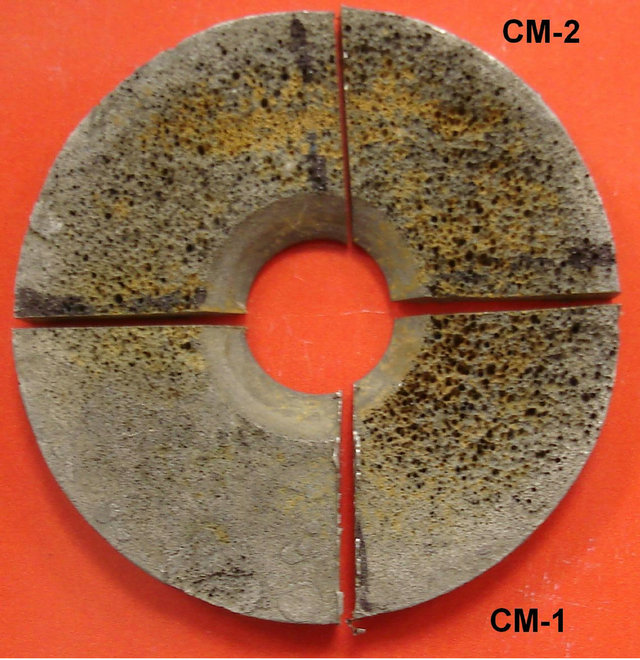
Figure 1. SAE 1018 Steel corrosion coupon. Pitting corrosion is observed at the metal surface.

Figure 2. Metallic samples covered by epoxy resin.
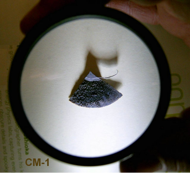
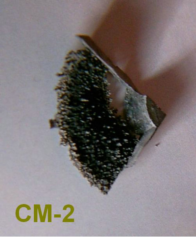
Figure 3. Epoxy samples, after steel dissolution.
rated during the corrosion process.
Later, the epoxy samples were covered with a gold film (of approximately 20 nanometers thickness), as shown in Figure 4. This was done, because of the epoxy dielectric characteristics and in order to observe the samples surface with the Scanning Electron Microscope (SEM).
It should be point out that the gold film on the epoxy does not interfere with the corrosion morphology, as the film thickness is very small (about 10 - 9 m) compared to the pits depth observed (10 - 6 m). Once the film was laid on the epoxy, the surface analysis was carried out.
Initially, the electrons beam was sent perpendicular to the sample surface. Figure 5 shows an SEM image (150×), obtained from the epoxy surface, exhibiting pitting corrosion. Because of the electron beam direction, images showing pitting density (number of pits per unit area) can be obtained. At the same time, the diameter of the pits is estimated. For this specific picture, a pit with a diameter of 318.49 μm is observed in the center of the image.
One important condition when using this methodology is the fact that several diameters can be estimated at the same time, including maximum and average size.
On the other hand, to evaluate pits depth, SEM images, considering different slopes to the horizontal, were obtained. Some photographs are shown in Figure 6, where different slope values were considered.
According to these images, it is possible to identify the
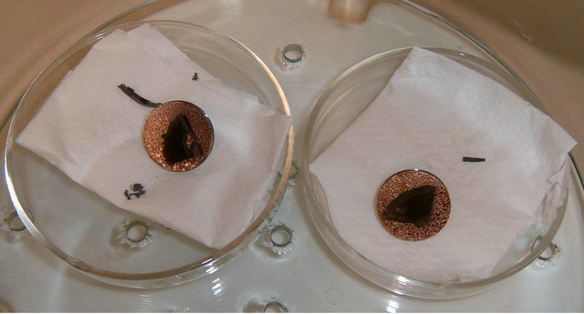
Figure 4. Epoxy samples, covered with a 20 nm gold film.
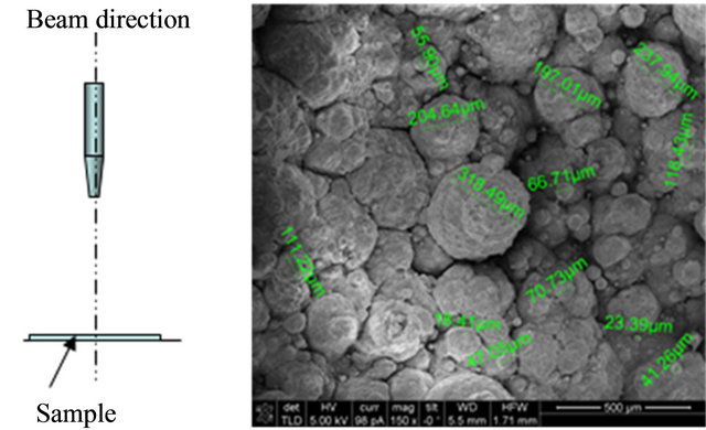
Figure 5. SEM image at 150×. Electron beam perpendicular to the sample surface.
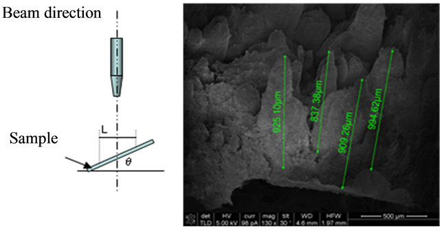
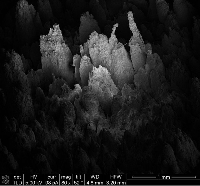
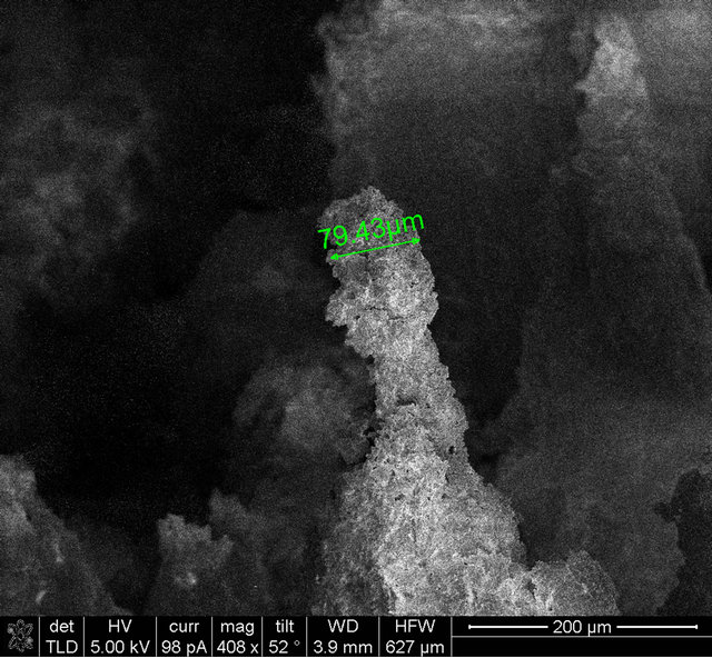
Figure 6. SEM images considering different slopes to the sample surface.
pits depth (represented by peaks in the photographs), considering the peak length for each one and using the next relation:
 (1)
(1)
where:
• P is the pit depth;
• L is the distance measured;
• θ is the slope angle from sample surface.
In this way, different pits can be evaluated at the same time, with one image. Also, average and maximum depths can de determined. Additionally, the SEM images allow identifying any corrosion preferential path occurring at the metal surface.
During pits depth determination, it is very important to establish a reference point, which allows knowing the magnitude with respect to the horizontal metal surface.
This condition becomes relevant when other types of corrosion, such as uniform corrosion, are observed along with pitting corrosion. Uniform corrosion could decrease the initial sample thickness and cause some errors during the evaluation of this parameter.
3. Conclusions
The use and application of the high vacuum epoxy penetration technique is considered as an alternating method to evaluate pitting corrosion.
The results obtained when applying this technique are satisfactory, as different parameters related to pitting corrosion analysis were identified:
• Pitting density;
• Distribution;
• Shape, size, diameter and depth, including average and maximum values;
• Corrosion preferential path.
For this specific case, the maximum pit depth is a very important parameter, considering that the material is under high pressure conditions, and a localized metal thickness decrease could originate a failure.
Within the advantages of this method, the follow can be mentioned:
• A real representation of the pitting corrosion process can be obtained;
• Different parameters related to pitting characterization can be evaluated from one image;
• Each pit diameter can be identified, including average and maximum values, no matter the type of defect observed at the metal surface;
• There are no limitations in determining pits depth;
• A pitting corrosion preferential path, occurring at the metal surface, can be identified.
4. Acknowledgements
Authors wish to thanks to the Microscopy Laboratory Satff of the Mexican Petroleum Institute for their invaluable help during the development of this work.
REFERENCES
- American Society for Testing Material G 46 - 94 (Reapproved 2005), Standard Guide for Examination and Evaluation of Pitting Corrosion.
- American Society for Testing Material G 48 - 03 (Reapproved 2009), Pitting and Crevice Corrosion Resistance of Stainless Steels and Related Alloys by Use of Ferric Chloride Solution.
- American Society for Testing Material G 1 - 03, Standard Practice for Preparing, Cleaning, and Evaluating Corrosion Test Specimens.
- American Society for Testing Material G 15 - 08, Standard Terminology Relating to Corrosion and Corrosion Testing.
- American Society for Testing Material G 16 - 95 (Reapproved 2004), Standard Guide for Applying Statistics to Analysis of Corrosion Data.
- American Society for Testing Material E 3 - 01 (Reapproved 2007), Standard Guide for Preparation of Metallographic Specimens.
- D. A. Jones, “Principles and Prevention of Corrosion,” Second Edition, Prentice Hall, 1996.
- J. T. N. Atkinson and H. VanDroffelaar, “Corrosion and Its Control,” Second Edition, National Association of Corrosion Engineers, Houston, 1985.