Materials Sciences and Applications
Vol. 3 No. 4 (2012) , Article ID: 18467 , 18 pages DOI:10.4236/msa.2012.34030
Property and Activity of Molybdates Dispersed on Silica Obtained from Various Synthetic Procedures
![]()
1Dipartimento di Chimica Fisica ed Elettrochimica (DCFE), Centro Interdipartimentale Materiali e Interfacce Nanostrutturati (CIMaINa), Università degli Studi di Milano, Milano, Italy; 2Department of Material Science, INSTM, University of Milano-Bicocca, Milano, Italy; 3Unité de Catalyse et Chimie du Solide UCCS UMR CNRS 8181, Université de Lille 1 Sciences and Technologies, Villeneuve d’Ascq, Lille, France.
Email: *antonella.gervasini@unimi.it
Received January 18th, 2012; revised February 19th, 2012; accepted March 24th, 2012
Keywords: Molybdena-Silica Mixed Oxides; Molybdenum Dispersed Phase; Catalyst Preparation; Catalyst Characterization; Catalytic Oxidation; Formaldehyde
ABSTRACT
The synthesis and characterization of several dispersed molybdena catalysts on silica support (MoO3-SiO2) prepared from a variety of precursors (Mo(VI)-acetylacetonate, oxo-peroxo Mo-species, hydrated ammonium heptamolybdate) and preparation methods (deposition of the Mo-phase on finite SiO2 support by aqueous and methanol impregnations, by adsorption, by oxo-peroxo route-like, and by one-step synthesis of MoO3-SiO2 system with molecular precursors) are presented. The molybdena concentration on silica was comprised in a large interval (1.5 - 14 wt%) depending on the preparation method which governed the Mo-loading on silica. Convenient comparisons among samples at similar Mo-concentration have been made discussing the morphologic-structural (XRD, XPS, UV-vis-DRS, and N2-adsorption) and physicochemical (TG-DTG, TPR, and n-butylamine-TPD) sample properties. Polymeric octahedral polymolybdate aggregates predominated in the samples prepared by aqueous and methanol impregnations, which were at high Mo-concentration. On the contrary, isolated Mo(VI) species in distorted Td symmetry predominated in the sample prepared by adsorption which was at very low Mo-concentration. The sample acidity was composed of a weak acidy site population, associated with the silica support, and a strong acid site population associated with the Mo-dispersed phase. Oxidation tests of formaldehyde, an oxygen-containing VOC (Volatile Organic Compound), were performed to determine the prevalent redox or acidic function of the Mo-species at the surface of the catalysts.
1. Introduction
Molybdenum containing catalysts are receiving great interest because of their importance both in environmental catalysis, such as combustion of soot, and in many industrial reactions, such as hydrodesulfuration, dehydrogenation of alkanes, partial oxidation of methanol to formaldehyde, and metathesis of olefins, among others [1-3]. The efficiency of these catalysts is strongly related to the amount and, in particular, the dispersion of the Mo-phase [4,5] which in its turn can be very influenced by the preparation method of the sample [6,7]. To improve the activity-selectivity behavior of the Mo-based catalysts in given reactions and the Mo-dispersion, new Mo-precursors and preparation methodologies are expected helping the development of even more performing catalysts.
Conventionally, hydrated ammonium heptamolybdate and impregnation are chosen as Mo-precursor and preparation method, respectively. Because of the acidic character of the aqueous molybdate solutions (pH value from 5 to 6) often used in the impregnations, the polymolybdate anions can bound to the support surface and can polymerize/depolymerize during calcinations [8-10] causing alteration of molybdenum aggregation. Supported Mo oxide catalysts can be successfully prepared exploiting the reaction of surface OH groups of the support with various Mo-organometallic compounds (e.g., Mo(h3-C3H5)4, Mo2(h3-C3H5)4, Mo(C4H7)4, etc.), by the so called adsorption equilibrium deposition method [11-13]. It is claimed that the surface of such catalysts bears a uniform distribution of defined Mo species, the structure of which can be controlled changing some synthesis parameter. Another successful synthesis proposed to develop highly dispersed Mo supported catalysts is via the so called oxoperoxo route [14,15] running through formation of low nuclearity oxo-peroxo species (e.g., when silica is concerned as support, ≡Si-O-Mo(OH)(O2)2 moieties are formed). The h2-peroxo ligands are good leaving groups easily decomposed during calcination to give oxo groups (e.g., (≡Si-O)2-Mo(O)2) with regular distribution on the surface. At last, the design of dispersed metal oxides with high surface area is nowadays attempted by one-step synthesis procedures. For these synthetic procedures, molecular precursors of both the support and metal phase and structure directing agents (like ionic or non-ionic surfactants) are used [16]. This strategy may be used for the synthesis of several supports containing metal oxide phases [17] giving rise to materials with good surface properties and catalytic activities.
Despite the literature presents many papers describing new preparation methods for Mo oxide containing catalysts, comprising those above cited, there is a certain lack of unified vision on the surface and bulk properties of these materials deriving from different preparations and different Mo-precursors.
This work reports our results on the synthesis and characterization of several molybdena containing catalysts over silica support (MoO3-SiO2) prepared from a variety of precursors (Mo(VI)-acetylacetonate, Mo-trioxide, hydrated ammonium heptamolybdate) and preparation methods (deposition of the Mo-phase on the finite SiO2 support by aqueous and methanol impregnations, by adsorption, by oxoperoxo route like, and one-step-synthesis of the MoO3-SiO2 system). A series of analysis of the main surface and bulk properties governing the catalytic properties of the samples have been made. Primarily, the method of preparation controlled the amount of molybdenum uptake from the silica support. We would like to show that it is possible to modulate the amount and surface properties of the dispersed molybdenum phase by a judicious choice of the Mo-precursor and preparation method. This should have important positive aspects in several applied catalytic fields where Mo-based catalysts are much used. The catalytic oxidation tests of formaldehyde, one among the most toxic indoor volatile organic compounds (belonging to Group 1 of the International Agency for Research on Cancer (IARC) classification [18]), have complemented this study. The product distribution observed on the catalyst samples could permit determining the prevalent redox or acidic function of the Mo species at the surface of the catalysts.
2. Experimental Procedure
2.1. Materials
The utilized molybdenum precursors were tetra hydrated ammonium heptamolybdate (NH4)6Mo7O24·4H2O (SigmaAldrich, 99.98% purity) (AHM), molybdenum acetylacetonate, MoO2(C5H7O2)2 (Alfa Aesar, 99% purity), and molybdenum oxide, MoO3 (Sigma-Aldrich, 95% purity). Tetra-ethoxy-silane (TEOS, Si(OC2H5)4, Fluka, 98% purity) was used as silica source. Polyoxyethylenepolyoxypropylene block copolymer ((C3H6O∙C2H4O)x, Sigma-Aldrich Pluronic F-68) and hexadecyl-trimethylammonium bromide surfactant (CTAB, (C16H33)N(CH3)3Br, Sigma-Aldrich, 99% purity) were used as structure-directing agents.
VICI Metronic permation tube with para-formaldehyde (grade purum, ≥95.0%) was used for the catalytic tests of catalytic oxidation.
2.2. Sample Preparation
The catalysts with general formula MoO3/SiO2 were prepared by different methods: by deposition of Mo-molecular precursors on a finite silica support or by one-step synthesis with molecular precursors following a sol-gel procedure.
The mesoporous silica (SIM) support was synthesized by a modification of the procedure described by Huh et al. [19] which consists of a condensation method based on sodium hydroxide-catalyzed reaction of TEOS, in the presence of low concentration of CTAB, followed by acid extraction of the as-made-product in a methanol mixture of hydrochloric acid. Details on the preparation and characterization can be found in Ref. [20]. For this study, the final obtained powder was calcined at 550˚C during 4 h.
The MoO3-containg samples were prepared depositing the Mo-precursors on SIM by 1) aqueous wet impregnation from the AHM inorganic complex (MoSi_ing); 2) alcohol impregnation from the MoO2(C5H7O2)2 organic complex (MoSi_org); 3) adsorption-deposition on silica of Mo ions contained in aqueous solution formed from thermal decomposition of AHM (MoSi_ads); 4) oxoperoxo route like method from oxo-peroxo Mo species generated from MO3 in H2O2 solution (MoSi_oxo). Moreover, a MoO3/SiO2 sample was prepared by onestep synthesis from TEOS and AHM molecular precursors, as silica and Mo oxide sources, respectively, in the presence of F-68 structure-directing agent (MoSi_os). All the five samples were prepared with the appropriate amounts of Mo-precursor and SIM (or TEOS) to obtain nominal amount of 10 wt% of Mo on silica. All the samples were calcined at 550˚C for 4 h to obtain the final powders.
For the MoSi_ing preparation, AHM was dissolved with stirring in water and the required amount of SIM was added. After 16 h at r.t., solution was stirred at 200˚C until total water evaporation (rate ca. 5 cm3/h). The obtained yellow solid was dried at 120˚C for 16 h (pale yellow dried solid) and eventually calcined. Almost analogously, MoSi_org was prepared dissolving MoO2(C5H7O2)2 with stirring in methanol at 40˚C until an intense orange clear solution was obtained, (the complete dissolution was controlled by UV-vis measurements at 272 nm); then the required amount of SIM was added. Solvent evaporation occurred at 80˚C (evaporation rate ca. 10 cm3/h), the obtained green solid was dried at 120˚C for 16 h (intense green dried solid) and calcined. The preparation of MoSi_ads consisted of several steps; the first step was the decomposition of AHM in water at 100˚C for 48 h. After filtration, the required amount of SIM was introduced into the obtained clear solution containing Mo ions. In the suspension, NH4OH was added to obtain basic solution so favoring the metal cation adsorption on the support; the formed pale yellow suspension was stirred for 24 h at r.t. (adsorption step). The solid was recovered by filtration under vacuum, it was dried at 120˚C for 16 h and calcined.
The MoSi_oxo sample was prepared by oxoperoxo route like, with a modification of the early method described in References [14,15,21]. Initially, MoO3 was dissolved in water at 60˚C obtaining a pale yellow solution, then a H2O2 solution (50 wt%) was added (H2O2/ MoO3 molar ratio of 25). The required amount of SIM was thus introduced and the pale yellow suspension obtained was stirred for 4 h at r.t. Finally, the solid was recovered by filtration under vacuum, dried at 120˚C for 16 h and calcined.
One step-synthesis of the MoSi_os sample was performed adjusting the synthesis procedure described in Ref. [17]. At first, suitable amount of F68 triblock copolymer (TEOS/F68 molar ratio of 2.3) was dissolved with stirring at 30˚C up to the formation of a complete clear solution, it was quickly added into a solution of AHM under vigorous stirring. After one hour, HCl solution (TEOS/HCl 2 M ratio of 0.08) and then suitable amount of TEOS were added with stirring at 40˚C for 24 h. The formed gel was then kept at 100˚C for 48 h without stirring; during this time, changes of colors were evidenced (from violet to dark blue to pale green). After being cooling to r.t., the solid was recovered by filtration under vacuum, washing with abundant water, drying at 120˚C for 16 h (green-yellow dried solid), and eventually calcined.
2.3. Sample Characterization
ICP-OES (Inductively Coupled Plasma Optical Emission Spectroscopy) analyses for the determination of the Mo amount were performed by the ACTIVA apparatus from Horiba JOBIN YVON. The powder samples were attacked by lithium tetraborate at 1100˚C, then dissolved with HCl (20% in water) and treated with H2SO4 plus HNO3 plus HF in becher, heating up to complete evaporation, and finally recovered with HNO3.
Scanning electron micrographs (SEM) were obtained by a JEOL JSM-5500LV coupled with energy dispersive X-ray spectroscopic (EDS) analyzer working at 20 keV to obtain quantitative information on the distribution of Mo and Si elements. On each sample, area regions of 100 µm were analyzed.
X-ray diffraction (XRD) patterns of the powder samples were carried out by a Philips PW1710 vertical goniometer diffractometer using Ni-filtered CuKα radiation (λ = 1.5406 Å) with a step size of 1˚ (2q) and a step time of 1 s. The patterns were collected over the 2q range from 3˚ to 80˚.
Surface area (SBET) and porosity were determined by N2 adsorption/desorption at –196˚C by using a Carlo Erba Sorptomatic 1900 instrument. Details can be found in Ref. [22]. All the samples (45 - 60 mesh particles) were thermally activated before the analysis in the glass-cell at 350˚C for 16 h under vacuum. Pore size distribution (PSD) was calculated from the desorption branch of the isotherm using the Barrett-Joyner-Halenda (BJH) model equation [23].
A thermogravimetric (TG) analyzer from PerkinElmer (TGA7) equipped with Pt crucible was used for the measurements of the dried and calcined samples. Analyses were performed in air flowing (60 ml·min–1) at constant rate (10˚C·min–1) of temperature increasing from 25˚C to 820˚C.
X-ray photoelectron spectroscopy (XPS) analyses were carried out by a Kratos Analytical AXIS ULTRA DLD spectrophotometer, with AlKα monochromatized exciting radiation (1486.6 eV). Pass energy of 160 eV or 40 eV for the acquisition of the general (0 - 1100 eV) or high-resolution (C 1s, O 1s, Si 2p, Mo 3d5/2, and Mo 3d3/2) spectra was used, respectively. The residual pressure in the analysis chamber was around 10–9 mbar. All the binding energy (BE) measurements were corrected for charging effects with reference to the C 1s photopeak of the adventitious carbon (284.60 eV).
Diffuse reflectance spectroscopy (UV-vis-DRS) measurements were performed on fine powders samples (without any treatment of activation) put into a cell with optical quartz walls by a Perkin-Elmer Lambda 35 instrument equipped with an integrating sphere and Spectralon® as reference material. Spectra were measured in absorbance mode in the 1100 - 190 nm range.
Temperature programmed reduction (TPR) experiments were performed in a home-modified Micromeritics Pulse Chemisorb 2700 apparatus. Because the catalysts contained different amounts of reducible Mo-phase, the sample mass used varied from 0.1 to 0.5 g (45 - 60 mesh particle size) to obtain k and P values of 80 s and 10˚C, respectively [24,25]. The samples were initially pretreated in O2/Ar (5.27% v/v) flowing (45 cm3·min–1) at 350˚C for 1 h. After cooling to 25˚C, the H2/Ar (7.96% v/v) reducing mixture flowed through the sample (15 cm3·min–1) whose temperature increased from 25˚C to 1050˚C at constant rate of 8˚C·min–1, maintaining the final temperature for 30 min. The H2 consumption was detected by a thermal conductivity detector (TCD) and the peak areas were calibrated with pure H2 injections (Sapio, Italy; 6.0 purity).
The acid properties of the silica support and Mo-samples were performed by thermodesorption analysis of n-butylamine (n-But) from saturated samples operating in an home-made modified temperature-programmed desorption mass spectroscopy (TPD-MS) instrument from Thermo Fisher Scientific. The amine saturation was performed on thermally activated sample (350˚C for 16 h), as described in several papers [26,27]. The TPD-MS analyses were carried out in a tubular quartz cell (32 cm long and 1 cm diameter) equipped with a porous septum for putting the sample (ca. 0.1 g, 45 - 60 mesh particle size) under He flowing (30 ml·min–1) monitoring simultaneously several signals: 12, 15, 18, 30, 32, 44, and 73 m/e as a function of temperature. At first, an isothermal step at 50˚C was performed to remove the excess of adsorbed amine from the surface until stable signal was obtained. Then, temperature was raised at 10˚C·min–1 to 650˚C, maintaining the final temperature for 50 min. Before and after the TPD-MS measurement (at 50 and 650˚C, respectively), known amount of n-But (ca. 3 μL) was injected into the sample and the integrated areas of the m/e = 73 peak were averaged to obtain the calibration factor (±10% deviation). Assuming a 1:1 stoichiometry for adsorbed n-But on the acid site, the total number of sites could be known and expressed as equivalent of acid site per sample unit mass or unit surface (mequiv·g–1 or mequiv·m–2).
2.4. Catalytic Test of Formaldehyde Oxidation
The formaldehyde catalytic oxidation was performed in a fixed bed reactor (i.d. 10 mm) loaded with ca. 200 mg of catalyst with particle size of 50 - 150 μm. The formaldehyde vapor was generated heating at 100˚C permeation tubes containing solid paraformaldehyde and mixed with the carrier gas (20% O2/He). The reaction mixture contained 300 ppm of HCOH. The total flow rate was 100 mL/min and the gas hourly space velocity (GHSV) was 30,000 mL/(gcat·h). The effluent gas from the reactor was analyzed in line by MicroGC (Varian 5400) equipped with Cox and 5CB columns connected to TCD.
Because the observed high adsorption ability of formaldehyde on the samples at room temperature, stable formaldehyde signal was waited before collecting the reactivity data. Once obtained the stable signal at 30˚C, the reactor was heated up from 30˚C to 450˚C with a heating rate of 1˚C·min–1.
3. Results and Discussion
3.1. Prepared Samples
Table 1 lists the prepared MoO3/SiO2 samples with the quantitative composition, determined by ICP-OES analysis. The two samples prepared by SIM impregnation from the polynuclear, (NH4)6Mo7O24·4H2O, and mononuclear, MoO2(C5H7O2)2, Mo-precursors (MoSi_ing and MoSi_org, respectively), had an amount of MoO3 as high as 12 - 14 wt%. On the contrary, the two samples prepared by metal adsorption and oxo-peroxo route like had lowest amount of MoO3 loaded on SIM, 1.2 and 3.8 wt%, respectively. About the same amount of MoO3 was present in MoSi_os (3.7 wt%). It clearly emerges that the preparation method had determined the amount of Mo oxide that was loaded on the support. As known, impregnation methods permit introducing the desired amount of metal phase over a given support while by employing other methods of deposition, the mutual characteristics of the support and metal precursor besides the conditions of the synthetic procedure govern the amount of metal which can be up taken by the support.
By assuming a uniform presence of Mo oxide on the

Table 1. Composition and textural properties of the support (SIM) and Mo oxide catalysts.
SIM support surface and known the SIM surface area, it was possible to compute the Mo surface density of each sample (Table 1). A large range of surface density from ca. 0.1 up to 1.3 atMo·nm–2 was found, the lowest densities were observed for the MoSi_ads and MoSi_oxo samples and the highest ones for the impregnated samples (MoSi_ing and MoSi_org), as expected.
The formation of the dispersed Mo oxide phase on the silica support necessitated of the calcination step which was carried out at 550˚C. This temperature ensured the complete decomposition of the used Mo-precursors leading to the formation of the oxidic phase, as shown by the TGA results obtained comparing the dried vs. calcined samples. Figures 1-3 report the TGA and DTGA curves for the only dried Mo-samples in the 20˚C - 820˚C temperature range collected in flowing air. The curves for MoSi_ing and MoSi_org (Figure 1) are similar; they presented a first loss of weight at very low temperature (ca. 50˚C - 100˚C) associated with physically adsorbed water at the surface or at the pore walls. For higher temperatures, both the curves had a marked loss of mass in the temperature range 200˚C - 300˚C due to Mo-complexes decomposition. Ammonia, from the AHM pre-
 (a)
(a)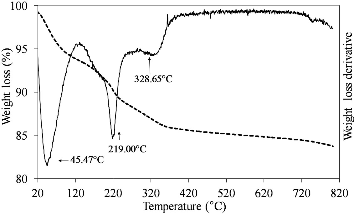 (b)
(b)
Figure 1. TGA/DTG profiles in air atmosphere (heating rate of 10˚C min–1) of the dried MoSi_ing (a) and MoSi_org (b) samples prepared by deposition of (NH4)6Mo7O24·4H2O on the SIM support.
cursor, completely decomposed at 309˚C (Figure 1(a)) while the dried MoSi_org had two peaks of mass loss, a pronounced one at Tmax of 219˚C and a broader one at higher temperature (329˚C). The high temperature zone of the TGA/DTGA curves (>750˚C) gave interesting information; Figure 1(a) showed very pronounced weight of loss at 800˚C associated with MoO3 sublimation. Figure 1(b) showed the starting of a similar event, in this case the MoO3 sublimation was likely shifted at higher temperature. The difference in sublimation temperature might be due to the use of the polynuclear, ((NH4)6 Mo7O24·4H2O), and mononuclear, (MoO2(C5H7O2)2), Mo oxide precursors in the two cases; the first one leading to larger aggregates of Mo oxide on the support surface which can sublimate more easily than the second one, leading to smaller Mo oxide aggregates.
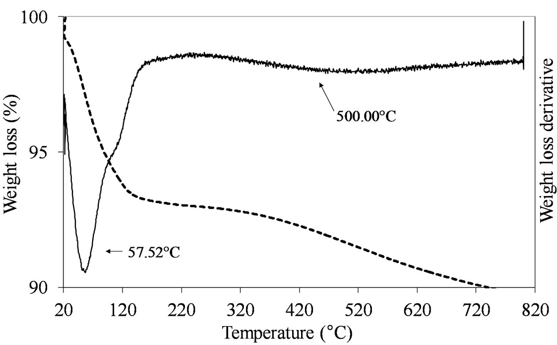
The samples prepared by adsorption and oxo-peroxo route like (MoSi_ads and MoSi_oxo) did not show any clear defined peak of weight loss in the temperature range from 150˚C to 820˚C, as expected due to the non-use of organic/inorganic complexes to form the Mo oxide dispersed phase (Figure 2).
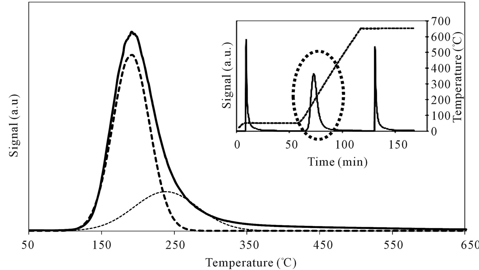
At last, the TGA-DTGA curves of dried MoSi_os
 (a)
(a) (b)
(b)
Figure 2. TGA/DTG profiles in air atmosphere (heating rate of 10˚C min–1) of the dried MoSi_ads (a) and MoSi_oxo (b) samples prepared by adsorption of Mo6+ ions and by addition of H2O2/MoO3 solution on the SIM support, respectively.
showed intense and continuous losses of mass from 50˚C to 350˚C range, due to the chemical species used during the sample synthesis (Figure 3).
3.2. Morphologic-Structural Properties
All the Mo-sample surfaces were analyzed by SEM-EDS spectrometry to determine the surface composition and the morphologic features. In general, the surface concentration of MoO3, determined by EDS, was lower than that determined from ICP analysis. In particular, a MoO3 concentration of 6.1, 10.5, 1.45, 2.9, and 1.6 wt% for MoSi_ing, MoSi_org, MoSi_ads, MoSi_oxo, and MoSi_ os, respectively, was determined.
The low MoO3 surface concentration determined for MoSi_ing might be due to the presence of large MoO3 aggregates (3-dimensional particles); in the case of MoSi_os, the presence of Mo both on the surface and in the bulk of the sample where it could not be detected by the EDS analysis, can be invoked. For all the other samples, the EDS and ICP measurements were not very different, suggesting that all the Mo loaded on SIM consisted of small Mo oxide aggregates (2-dimensional particles) (see Figure 1 of Supporting Information for a representative SEM image and EDS spectrum).
Concerning the sample BET-surface area values, in general the SIM coverage from Mo oxide phase led to a more or less marked decrease of surface area compared with that of bare SIM; the values are not in any clear relation with the amount of Mo oxide loaded on the support (Table 1). The results suggest that higher surface areas values were obtained when the Mo oxide aggregates could enter into the SIM mesopores while when wider Mo oxide aggregates were formed, they arranged on the external surface of SIM blocking the pore entrance and causing a more important decrease of surface. The pore size distribution (PSD) of SIM presented a unique pore size population (centered at 2.6 nm of size) while the Mo-samples presented bimodal pore size distributions (Table 1), one of low size (from 1.9 to 2.4 nm) and the other of higher size (from 3.2 to 3.7 nm). The partial filling of the mesopores of SIM by the Mo oxide aggregates gave rise to the smaller pore size population (PSD < 2.6 nm), while the wider Mo oxide aggregates developed a pore size population of larger size (PSD > 3.2 nm). The MoSi_os sample had very high surface area and porosity (529 m2·g–1 and 0.33 cm3·g–1, respectively); a main PSD population around 3.2 nm of size was observed.
X-ray powder diffraction patterns (XRD) of the Mosamples are compared in Figure 4. In all the patterns, a broad band in the 20˚ - 30˚ 2θ characteristic of unstructured silica appeared. The patterns of the two highest Mo concentrated samples (MoSi_ing and MoSi_org) are similar and reveal the main presence of stable phase or-

Figure 3. TGA/DTG profiles of the MoSi_os sample prepared by one step synthesis with a sol-gel procedure.
thorhombic α-MoO3 with co-presence of the meta-stable hexagonal h-MoO3, in lower amount. A semi-quantitative evaluation of the cristallite size (by Scherrer law) gave 45 - 60 nm for the particle dimension. All the other samples displayed XRD patterns typical of amorphous materials without the possibility to know if the absence of any diffraction peak was due to absence of long-range order of the MoO3 phase or to the too low amount of MoO3 to observe diffraction.
3.3. XPS Surface Properties
The identification of the Mo oxidation state by XPS is based on the binding energies of the Mo(3d5/2, 3d3/2) spin-orbit components. It is known that various parameters affect the absolute values of the binding energy of the Mo(3d5/2, 3d3/2) doublet of Mo(VI)-oxo species. Among these, Mo loading, metal-support interaction, and surface oxygen coordination around the Mo centers [28- 32]. Literature reports special attention on the dependence of the Mo oxide-support interaction on the support nature [31-35]. From these studies, it emerges that the Mo oxide-support interaction strength is reflected by the binding energy value of the Mo 3d5/2 - Mo 3d3/2 doublet: the stronger the molybdena-support interaction, the higher the binding energy. In fact, higher binding energy of the Mo 3d5/2 - Mo 3d3/2 doublet for the MoO3/Al2O3 system in comparison with that of MoO3/SiO2 is reported. In addition strong metal-support interaction is expected to occur when molybdena is spread on the surface hydroxyl groups of support realizing high Mo-dispersion [36-38].
The collected results (Figures 5-7) show, with some degree of ambiguity, that all the used preparation routines gave to formation of Mo(VI) oxo-species, even if some reduced Mo oxo-species could be co-present. The obtained XPS values corresponded to those reported for supported Mo oxo-species in the highest oxidation state [29-31]. However, the binding energies of Mo 3d5/2 are shifted at lower values as compared to that of bulk MoO3

Figure 4. X-ray diffraction patterns of all the Mo-samples: A. MoSi_ing; B. MoSi_org; C. MoSi_ads; D. MoSi_oxo; E. MoSi_os.
 (a)
(a)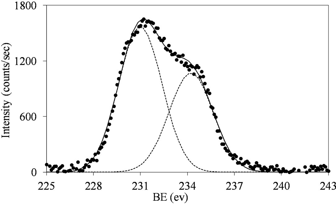 (b)
(b)
Figure 5.XPS spectra of the Mo 3d region (Mo 3d5/2 and Mo 3d3/2) for the MoSi_ing (a) and MoSi_org (b) samples with peak decomposition.
(231.7 eV) [39]. This may indicate the surface presence of some reduced Mo species (MoOx with x < 3).
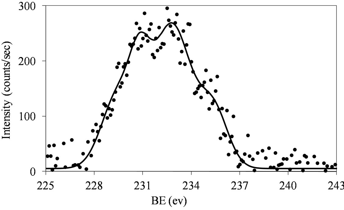
Figures 6 and 7 show that at low molybdena loading (MoSi_ads, MoSi_oxo, and MoSi_os), the doublet is broadened with poor resolved peaks, in comparison with what was observed on MoSi_ing and MoSi_org (Figure
 (a)
(a)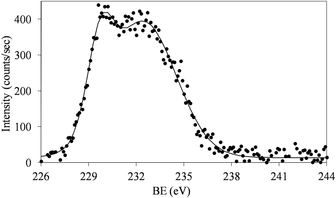 (b)
(b)
Figure 6. XPS spectra of the Mo 3d region (Mo 3d5/2 and Mo 3d3/2) for the MoSi_ads (a) and MoSi_oxo (b) samples.
5) for which the width of the peaks has tendency to decrease and the doublet resolution improves.
The broadening of the Mo 3d5/2 - Mo 3d3/2 doublet is normally explained either by the presence of several Mo(VI) oxo-species which differ in the strength of interaction with the support or by the presence of some reduced Mo species [32,40]. MoSi_ing and MoSi_org have
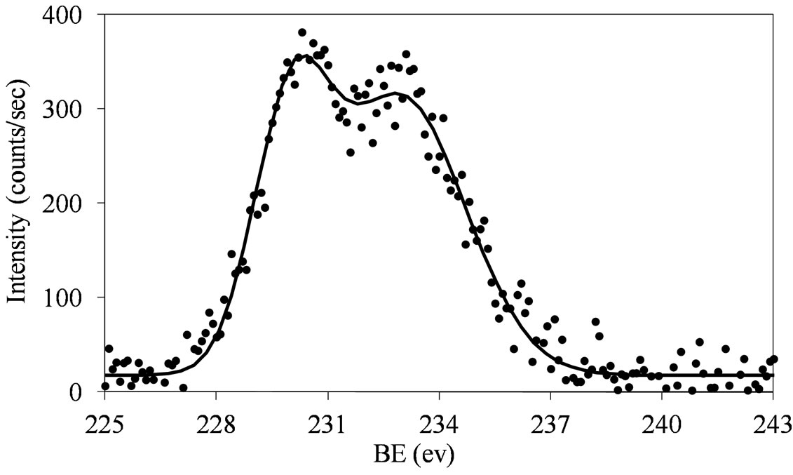
Figure 7. XPS spectra of the Mo 3d region (Mo 3d5/2 and Mo 3d3/2) for the MoSi_os sample.
similar behavior: the Mo(3d3/2, 3d5/2) values are observed at around 234, 231 eV, respectively, with intensity ratio, I(Mo 3d5/2)/I(Mo 3d3/2), near to 3/2 (1.46 for MoSi_ing and 1.45 for MoSi_org) and with value of the splitting energy for the Mo 3d5/2-Mo 3d3/2 doublet at 3.2 eV, in both the cases.
The fitting of the experimental XPS envelopes of Mosi_oxo and MoSi_os cannot satisfactory be made with only one individual Mo 3d5/2 - Mo 3d3/2 doublet; the low intensity of the photo-peaks prevented a reliable fitting to be computed. The MoSi_ads sample showed the more complex situation in which more than two individual Mo(3d3/2, 3d5/2) doublets were needed to reproduce the experimental XPS envelopes, suggesting the presence of at least two types of molybdenum species which differ in the strength of interaction with the silica support.
Mo surfacing was calculated for all the samples taking into account the surface Mo-concentration, determined from XPS data, and that obtained from ICP-OES (Table 1). In general, values equal or higher than 0.5 were observed in any case. The lowest Mo surface concentrations were found on MoSi_ing and MoSi_org (0.45 and 0.56, respectively). Within the preparation routine of impregnation, the use of the mononuclear Mo precursors led to better dispersion of the Mo oxide phase that the use of the polynuclear complex ((NH4)6Mo7O24·4H2O). Higher surfacing values were found for MoSi_oxo and MoSi_os (0.76 and 1.0, respectively) which are both at low Moloading and high Mo-dispersion. MoSi_ads has the highest Mo surfacing value (1.43). Considering the experimental error in the evaluation of the very low Mo concentration, we can consider that total Mo-dispersion on silica was obtained in this case.
3.4. UV-VIS-DRS Electronic Properties
The electronic spectra of the studied Mo-catalysts are characterized by the absence of any absorption in the visible region according to the d0 configuration of molybdenum, which excludes the occurrence of d-d crystal field transitions.
For MoO3, the electron transfer occurs from the oxygen 2p orbital to the metal d orbital; ligand-metal charge transfer (LMCT) bands are then expected dominating the UV region of the electromagnetic spectrum. They can be used for characterizing local surface structures of Mo oxo species dispersed on the silica surface [41,42]. Octahedral ( , Oh) or tetrahedral (
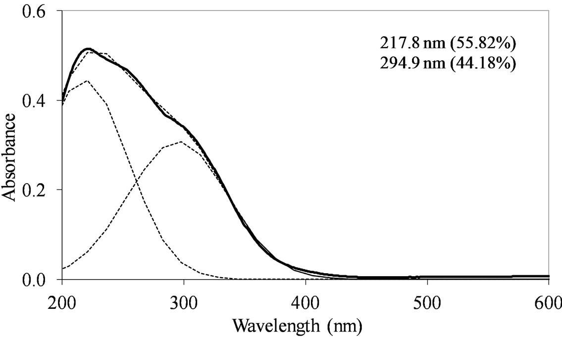
 , Td) coordination for the Mo(VI) species of the samples could be identified starting from an inspection of the UV-DRS bands. Traditionally, absorption bands from 250 to 280 nm have been assigned to Mo(Td) and bands from 300 to 330 nm to Mo(Oh) [43-45]. Moreover for oxide-supported Mo(VI), early authors have attributed the formation and growth of the electronic bands above 300 nm to a change in local molybdenum symmetry from Td to Oh [46]. This is also in agreement with the absorption value of some reference Mo-compounds. with tetrahedrally or octahedrally coordinated molybdenum (230 and 325 - 330 nm for Na2MoO4 and (NH4)6Mo7·4H2O, respectively) [43] There is a less clear and simple situation concerning the attribution of the ligand charge-transfer transitions of the Mo-O-Mo groups, which can be present in Oh polymolybdate when high Mo oxide concentration is concerned. The absorption wavelengths attributed to Mo-OMo structures are reported both at 250 - 295 and 320 - 340 nm [9,47], with significant overlap with the absorptions of Mo(Td) and Mo(Oh) species.
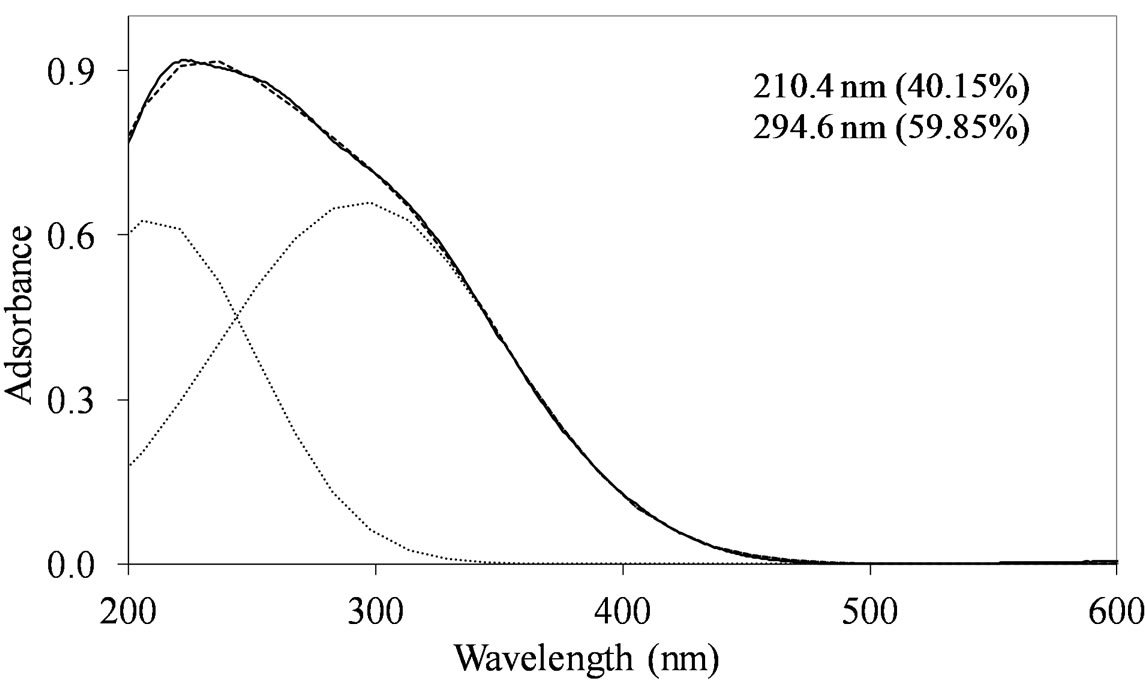
On all the samples, the observed broad electronic bands could be decomposed into two main absorption components with satisfactory fitting (Figures 8-10). Maxima are centered at 200 - 220 nm and 290 - 300 nm with a small tail at higher wavelength (400 nm) observed only on MoSi_oxo. The UV-DRS spectra of MoSi_ing and MoSi_org (Figure 8) have similar shape of the bands, similar values of the maxima of the decomposed bands, and similar proportion between the lower and higher wavelength bands. The high and low wavelength bands may be assigned to  species in Oh symmetry and
  species in Td or distorted Td symmetry, respectively. The absence of electronic bands at wavelength higher than 300 nm suggested us to rule out the presence of large MoO3 nano-aggregates.
MoSi_ads (Figure 9) presents similar situation of MoSi_ing and MoSi_org; in this case there was more clear presence of the  species in Td or distorted Td symmetry which predominated over the
  species. MoSi_oxo presents a different situation with absorptions centered at 223 and 303 nm and a little absorption at very high wavelength of 402 nm. This indicates a broad distribution of Mo species with well tetrahedrally and octahedrally coordinated Mo oxide species and some amount of MoO3 nano-aggregates.
The shape and position of the UV-DRS bands of
 (a)
(a)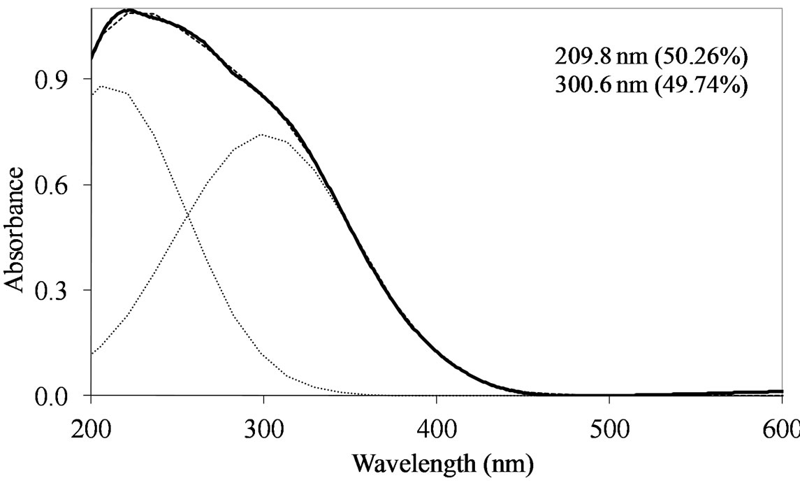 (b)
(b)
Figure 8. UV-DRS spectra of the MoSi_ing (a) and MoSi_ org (b) samples with curve peak decomposition. The calculated maximum absorption wavelengths and percentage area of the relevant peaks are indicated.
MoSi_os (Figure 10) are different from of all the others samples. Concerning the peak at lower wavelength, a clear shift towards low wavelength was observed (194 nm). The other absorption centered at maximum wavelength of 288 nm was very prominent and dominated the spectrum; in this case, Oh polymolybdate groups might be responsible of the absorption. Mo-reticulation could occur during the synthesis of this sample.
Very recently the literature reports on connected molybdenum oxide centers supported on SBA-15 [48] prepared from molybdenum acetylacetonate in ethanol. In agreement with our findings, these authors found in our same range of Mo-loading (ca. 1 atMo/nm2) that the molybdenum oxide surface species are composed of both dior oligomeric molybdenum oxide centers and isolated centers, with a mixture of octahedrally Mo-units with connectivity similar to that of MoO3, and tetrahedrallyMo units which are isolated or connected to other MoxOy units. In our case, we generally observed absence of typical UV-DRS bands that could be associated with 3dnanostructured MoO3 aggregates (UV-DRS band with maximum > 300 nm) reflecting well dispersion of the supported phase irrespective of the Mo concentration. It
 (a)
(a)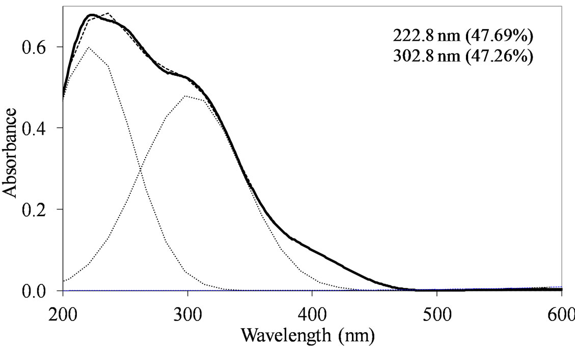 (b)
(b)
Figure 9. UV-DRS spectra of the MoSi_ads (a) and MoSi_ oxo (b) samples with curve peak decomposition. The calculated maximum absorption wavelengths and percentage area of the relevant peaks are indicated.

Figure 10. UV-DRS spectra of the MoSi_os sample with curve peak decomposition. The calculated maximum absorption wavelengths and percentage area of the relevant peaks are indicated.
could be guessed that the deposition of Mo oxo centers on silica begins with formation of isolated Mo(VI) centers in Td or distorted Td symmetry. When the surface Mo concentration increases, symmetry of the metal species changes along with formation of  species in Oh symmetry; in fact the broad absorption curve at ca. 300 nm growths and its maximum shifts from about 290 to 305 nm; at last, the high connectivity between Mo-centers gives rise to Oh polymolybdate groups. This view is also in agreement with the study of Christodoulakis and Boghosian [5] concerning the formation and growth of the molybdena dispersed phase on zirconia support which was realized by Raman spectroscopy. Direct observation of monomolybdates species and polymeric Mo-oxo units with Mo-O-Mo bridges on zirconia support was reported, the last one predominating at high Mo surface density.
3.5. Temperature Programmed Reduction (H2-TPR)
The H2-TPR profiles of bulk MoO3 activated in the temperature range from 400˚C to 600˚C are available in the literature [49-51]. The onset temperature of reduction is around 490˚C - 530˚C, temperature of peak maxima (Tmax) around 740˚C - 760˚C, and H2 consumption values account the stoichiometric reduction of MoO3 to Mo(0) (H2/MoO3 molar ratio = 3). The reduction pattern has been generally rationalized in the light of the stepwise process: Mo(VI) → Mo(IV) → Mo(0). The difficulty in developing a model describing the TPR pattern of the bulk and supported MoO3 systems mostly arises from the occurrence of numerous peaks generated by the various Mo(VI) forms having different reducibility [49]. Concerning the influence of preparation method and support nature on the Mo-speciation, Wachs et al. [52-54] stated that neither the preparation method nor the specific silica used influence the relative distribution of the Mo oxide species, which nature and growth only depend on Moloading.
The obtained TPR profiles reveal very complex shapes with several more or less marked maxima in a large temperature interval without the possibility to clearly distinguish intermediate steps of reduction from Mo(VI) to zerovalent Mo. The complexity of the profiles might be due to the coexistence of various MoSi-oxo species different for coordination type and size and then differently reducible (according with the above discussed UV-DRS results). For all the samples, three main peaks could be individuated corresponding to temperatures (Tmax) at which maxima reducing rates occurred. The Tmax values for all the samples are listed in Table 2: Tmax,1 values are around 500˚C, Tmax,2 around 700, and Tmax,3 around 800˚C or higher. It is expected that [49-55] the more dispersed and isolated MoOx species are more difficult to be reduced than the MoOx clusters, being the first one in higher contact with the support matrix.
Despite the similar Mo concentration of MoSi_ing and MoSi_org, they showed different TPR profiles (Figure 11); MoSi_org had higher reduction extent at low temperature than MoSi_ing. It can be inferred that more numerous MoOx clusters had formed on the MoSi_org surface (reduction in the temperature range 500˚C - 800˚C) than on MoSi_ing, while more numerous MoOx species in interaction with the support (reduction at temperature higher than 800˚C) are present on MoSi_ing.
The two samples, MoSi_ads and Mo oxo (Figure 12) have similar TPR profiles, similar amount of H2-consumed, and similar Tmax values (Table 2); only the proportion of the H2-consumed in the low and high temperature interval changes. MoSi_oxo has higher intensity of the TPR peak at low temperature, suggesting the
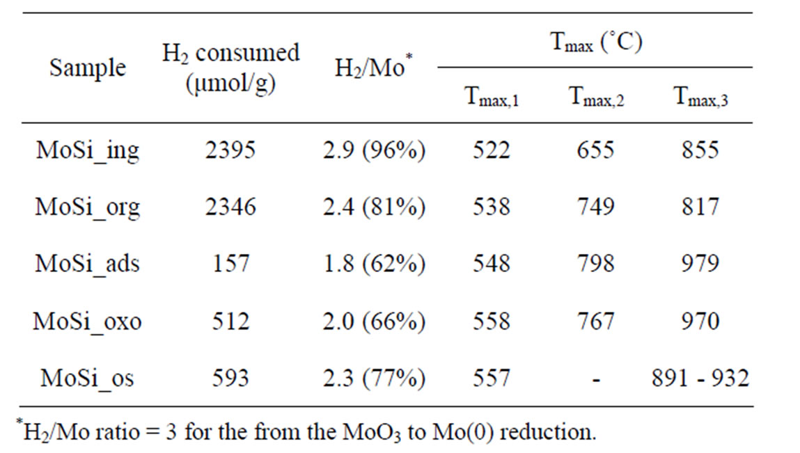
Table 2. Redox properties of the MoO3 phase determined by H2-TPR measurements.
 (a)
(a)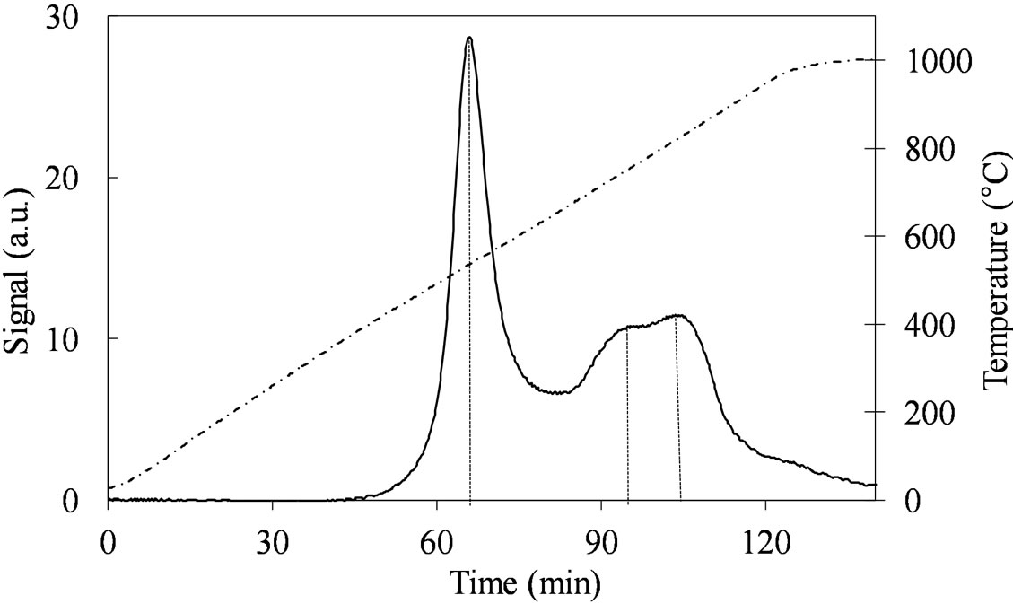 (b)
(b)
Figure 11. H2-TPR profiles of the MoSi_ing (a) and MoSi_ org (b) samples collected in the 30˚C - 1000˚C temperature range (see right axis) at heating rate of 8˚C∙min–1.
 (a)
(a) (b)
(b)
Figure 12. H2-TPR profiles of the MoSi_ads; MoSi_oxo samples collected in the 30˚C - 1000˚C temperature range at heating rate of 8˚C∙min–1.
presence of more easily reducible Mo-species than on MoSi_ads.
The TPR profile of MoSi_os (Figure 13) is very different from all the others. The Mo-reduction starts with a low H2-consumption at Tmax of 557˚C and then it continues at higher temperatures (891˚C - 932˚C) with a unique and quite symmetrical peak of reduction of very high intensity. Surely, this sample reveals more homogeneous situation for the Mo-phase in comparison with all the others samples.
3.6. Acid Properties
It is generally accepted that the acid properties of the catalytic surfaces determine the activity and selectivity of many reactions, not only in typical acid-base transformations but also in reduction or oxidation reactions [56]. How much acidity can be introduced to a given oxide support by the molybdenum oxide addition is of utmost importance to the catalyst design which has to work in a given reaction. Catalysts containing dispersed Mo centers on oxide supports are known to have high acid properties due to the development of molybdate and polymolybdate species possessing Brönsted and Lewis acid sites [57,58]. The silica surface contains hydroxyl groups which are
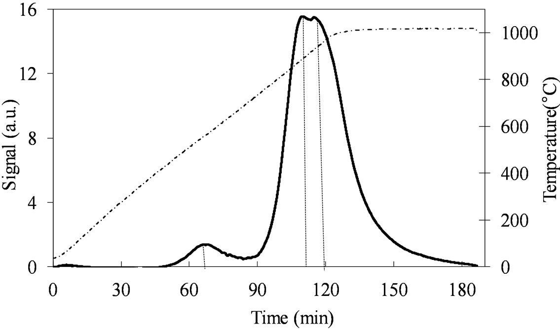
Figure 13. H2-TPR profiles of the MoSi_os sample collected in the 30˚C - 1000˚C temperature range (see right axis) at heating rate of 8˚C∙min–1.
weakly acid or neutral, then the deposition of Mo-phase is expected to give rise to a remarkable increase of acidity. Kataoka and Dumesic [57] found both Lewis and Brönsted acidity on high loaded MoO3/SiO2, whereas they found only Lewis sites in weakly loading systems (1 - 6 wt% MoO3). The Mo loading and the Mo speciation at the sample surface could affect not only the amount of acid sites but also the acid strength and acid distribution.
We chose to study the acid properties of the samples by TPD-MS using n-butylamine as basic probe. This is a conventional approach in the solid acidity studies giving the possibility to determine the amount of acid sites and the acid strength of the sites.
Table 3 reports the obtained results in terms of temperature corresponding to the maximum rate of n-butylamine desorption (Tmax) and of amount of acid sites per unit mass and per unit surface (meq/g and μeq/m2) for the support and Mo-samples. SIM has a homogeneous acid surface (Figure 14) with high amount of acid sites characterized by low acid strength (Tmax = 199˚C).
When SIM was covered by high amount of Mo oxide, as for MoSi_ing and MoSi_org (Figure 15), it was found a decrease of the acid site amount because large portion of the acidic support surface was covered, but new stronger acid sites appeared due to the Mo-phase presence. The TPD profiles showed a new peak of desorption at higher temperature than on SIM (Tmax of 218˚C and 220˚C for MoSi_ing and MoSi_org, respectively). The desorption peak of n-buylamine associated with the Mosites was about 50% of the total acidity of the two samples (Table 3).
On MoSi_ads and MoSi_oxo (Figure 16), the acidity presence was not very high, only about 27% of acid sites had increased acid strength compared with the SIM acid strength.
MoSi_os showed very high amount of acid sites, higher than the support and all the Mo-samples (Figure 17). A peculiar trend for the acid site strength was observed; the lowand high-temperature of n-butylamine desorption
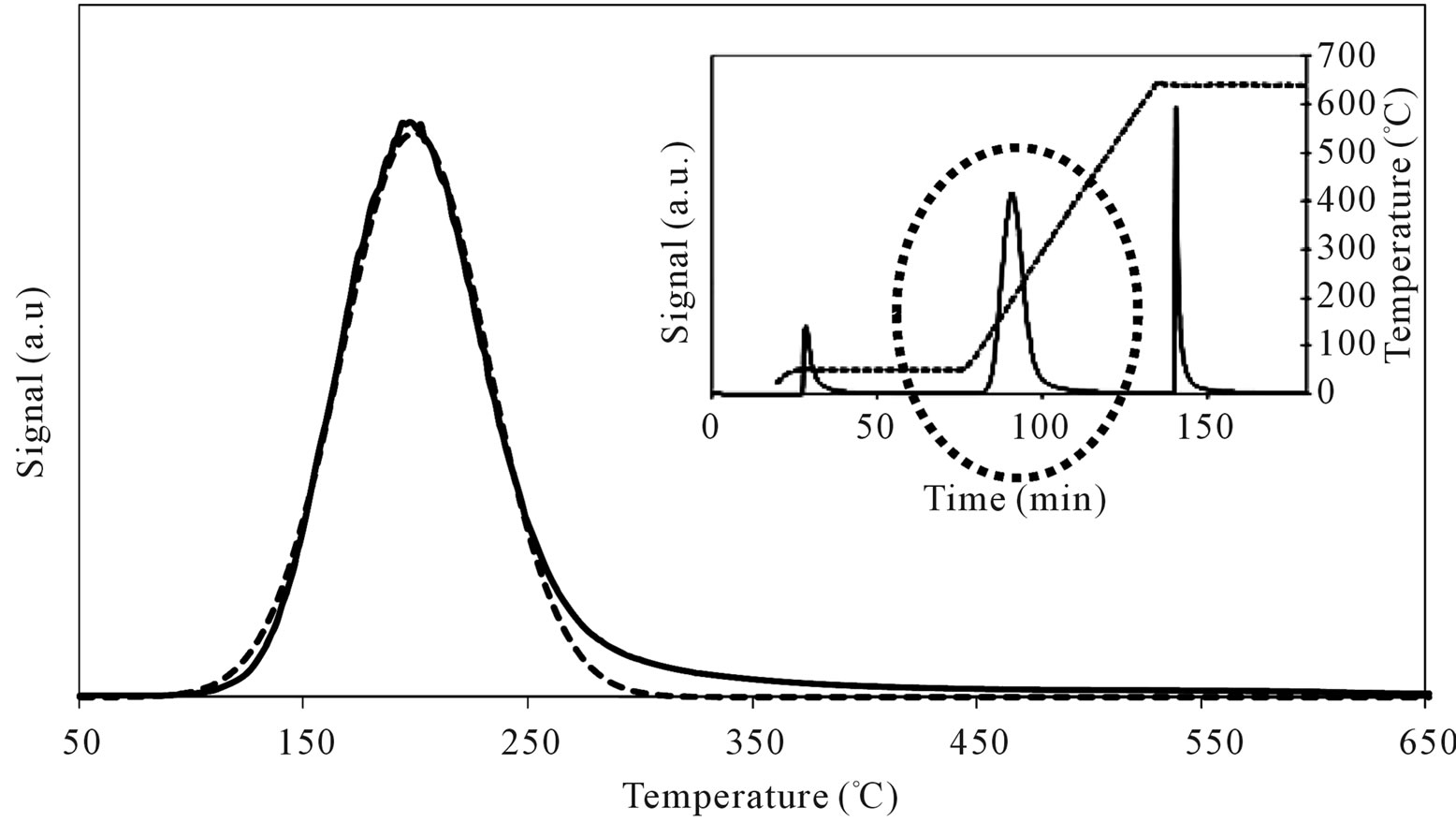
Figure 14. N-butylamine TPD-MS spectra (heating rate, 10˚C∙min–1; 73 m/e signal is reported) of the SIM support. Inset reports the development of the whole experiment; before and after n-butylamine TPD, calibration was performed by injecting known amount of butylamine.
 (a)
(a)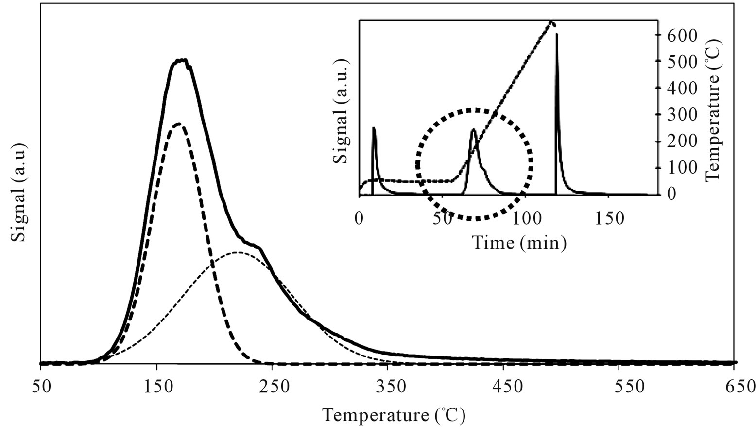 (b)
(b)
Figure 15. N-butylamine TPD-MS spectra (heating rate, 10˚C∙min–1; 73 m/e signal is reported) of the MoSi_ing (a) and MoSi_ org (b) samples. Inset reports the development of the whole experiment; before and after n-butylamine TPD, calibration was performed by injecting known amount of butylamine.
 (a)
(a) (b)
(b)
Figure 16. N-butylamine TPD-MS spectra (heating rate, 10˚C∙min–1; 73 m/e signal is reported) of the MoSi_ads (a) and MoSi_ oxo (b) samples. Inset reports the development of the whole experiment; before and after n-butylamine TPD, calibration was performed by injecting known amount of butylamine.
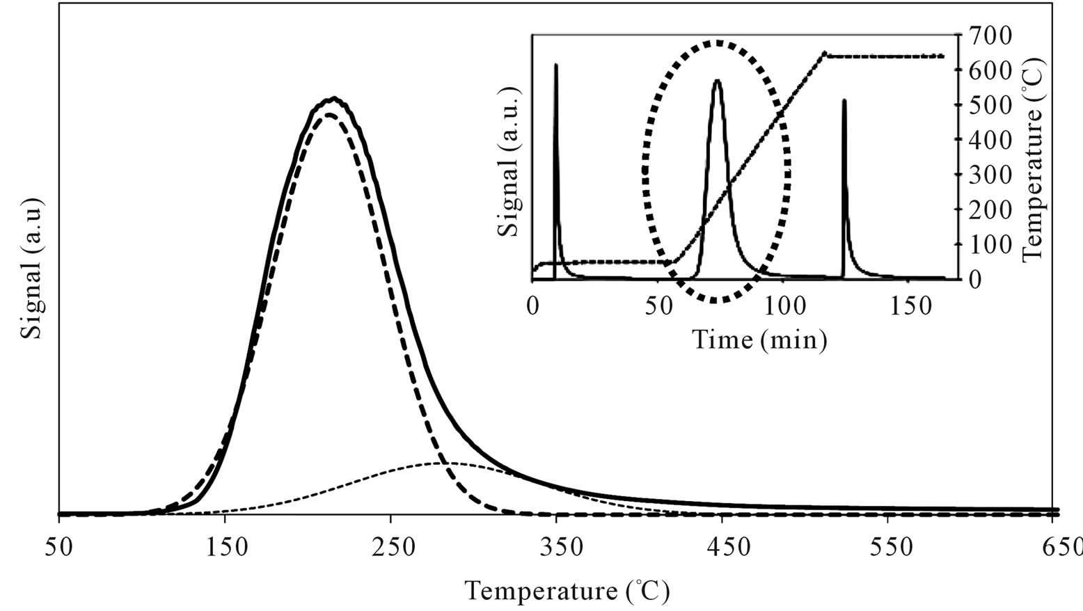
Figure 17. N-butylamine TPD-MS spectra (heating rate, 10˚C∙min–1; 73 m/e signal is reported) of the MoSi_os sample. Inset reports the development of the whole experiment; before and after n-butylamine TPD, calibration was performed by injecting known amount of butylamine.

Table 3. Acidity properties of the samples determined by TPD-MS of n-butylamine desorption*.
peaks were in different positions in comparison with those observed on SIM and on all the others Mo-catalysts (Table 3). The low acidity was prevalent (82%) and the high acidity was ca. 18% of the total. This behavior strengthens the above interpretations from spectroscopy results that polymolybdates were formed on the surface of MoSi_os. The polymolybdate species give rise to Brönsted acid sites which differ in acid strength compared with molybdate species formed on the others samples.
3.7. Catalytic Activity: Formaldehyde Oxidation
The catalytic oxidation of formaldehyde vapor gave carbon monoxide and carbon dioxide as only reaction products whatever the catalyst used. The obtained results are presented in the Figures 18-21 as molar fraction of the vented compounds (formaldehyde, carbon dioxide, and carbon monoxide) as a function of reaction temperature. Over SIM (Figure 18), the formaldehyde oxidation was possible but only at temperatures higher than 300˚C with the highest conversion observed of 28% at 400˚C. This could be due to the moderate surface acidity of the used silica that was able to adsorb high amount of formaldehyde over it and starting from a given temperature it can be oxidized. In agreement, Mao and Vannice [59] found silica to be inactive for the same reaction in the temperature range between 100˚C and 240˚C. Cheng [60] showed that silica was relatively inactive as total oxidation catalyst at 300˚C but it was able to oxidize formaldehyde to methanol and methyl formate, as well as CO and CO2. More recently McCormick et al. [61] found also that the formaldehyde oxidation over silica leads to CO2 and CO (with low formaldehyde conversion, <14%) in the temperature range 350˚C - 400˚C, being CO2 the major product (75%).
Over all the Mo containing samples, the catalytic behavior above described was observed, too, but MoSi_org. In general, the increase of formaldehyde conversion and variation between the CO to CO2 ratio were the main differences observed between the sMo-samples and SIM. Over MoSi_ing and MoSi_org in the high-temperature interval (300˚C - 450˚C), the CO product almost disappeared (Figure 19 and Table 4). This result can be explained by the oxidation of CO into CO2 over the molybdenum species which could work under a classical redox cycle [49] (Mo(VI) → Mo(IV)). MoSi_org catalyst presented a singular catalytic behavior since at very low
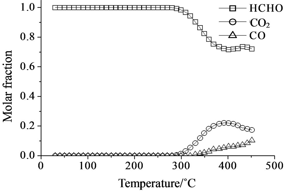
Figure 18. Catalytic test of oxidation of formaldehyde (300 ppm) on the SIM support: molar fraction of the formed products measured as a function of reaction temperature.
 (a)
(a)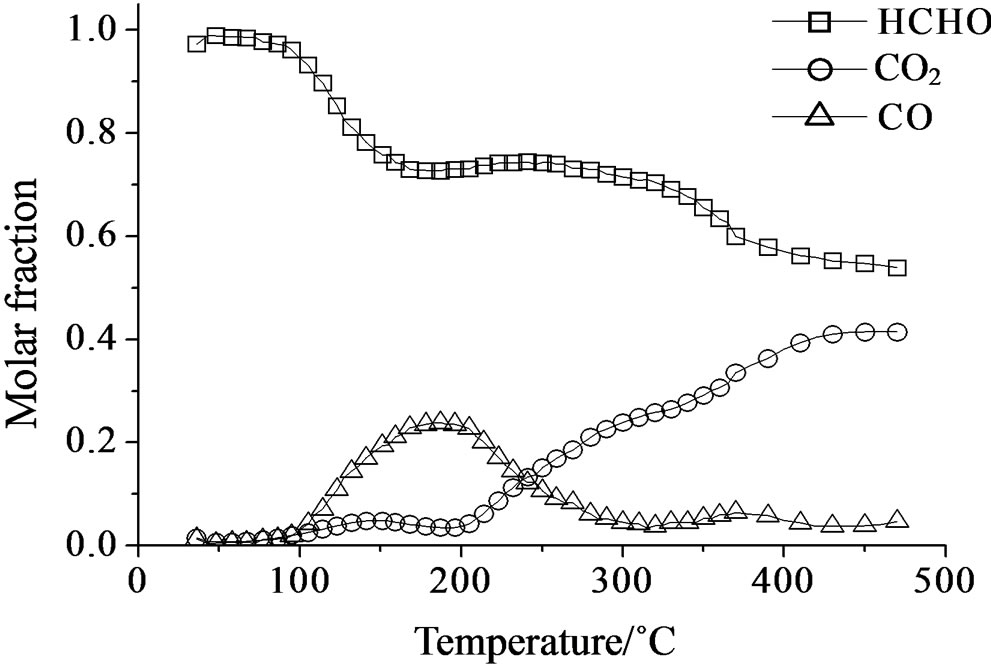 (b)
(b)
Figure 19. Catalytic test of oxidation of formaldehyde (300 ppm) on the MoSi_ing (a) and MoSi_org (b) samples: molar fraction of the formed products measured as a function of reaction temperature.

Table 4. Catalytic results of formaldehyde oxidation*.
temperature (around 100˚C) formaldehyde was converted into CO (Table 4). This catalytic result is hardly to be explained; MoSi_org has higher reduction extent at low temperature than MoSi_ing with presence of weaker interaction of the Mo oxo species with the silica support. This behavior can favor the formaldehyde interaction with the Mo centers which can start the oxidation reaction at low temperature.
Concerning the catalytic activity of MoSi_ads, MoSi_ oxo (Figure 20) and MoSi_os (Figure 21), they all showed similar results. The formaldehyde conversion increased up to 30% - 40% at 400˚C with predominance of CO2, even if CO was still present among the products at such high temperature (Table 4).
In conclusion, it can be considered that catalyst acidity is suitable to create accumulation of formaldehyde on the sample surface without the ability to oxidize it, while the presence of developed MoO3 structure is beneficial for the oxidation activity which likely passes through a redox mechanism. Based on these consideration, MoSi_ ing and MoSi_org with large MoO3 aggregates showed the better selectivity to CO2 during reaction at high temperature.
4. Conclusions
The possibility to create silica surfaces containing Mo oxo species with high or low Mo content and then associated with more aggregated or dispersed Mo-species if mainly directed by the preparation procedure. The choice of the Mo-precursor is a parameter which lightly affect the final sample properties.
The Mo-speciation distribution obtained on low or high Mo-loading silica samples affect the redox and acid properties of the samples, in particular. The molybdena phase can be in strong interaction or not with the support or the interaction between the metal centers can prevail over the metal-support ones. The acid properties of the Mo-samples were higher when weak metal-support interactions were active; this was observed at medium-high
 (a)
(a)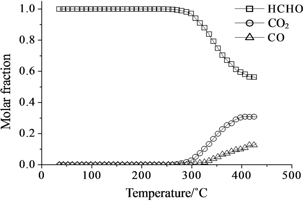 (b)
(b)
Figure 20. Catalytic test of oxidation of formaldehyde (300 ppm) on the MoSi_ads (a) and MoSi_oxo (b) samples: molar fraction of the formed products measured as a function of reaction temperature.
Mo-concentration on the surface. The redox properties of the molybdena dispersed phase were enhanced when a critical size structure of MoO3 clusters were formed. A judicious choice of the synthesis parameters of the Mosamples should permit tuning the chemical properties of the samples to obtain surfaces with different chemical properties.
5. Acknowledgements
Acknowledgements have to be addressed to Dr. Vladimiro
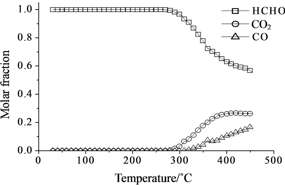
Figure 21. Catalytic test of oxidation of formaldehyde (300 ppm) on the MoSi_os sample: molar fraction of the formed products measured as a function of reaction temperature.
Dal Santo, Consiglio Nazionale delle Ricerche (CNR), Istituto di Scienze e Tecnologie Molecolari, Milano, Italy, for his assistance in several analytic measurements. A Gervasini thanks the University of Lille-1 for the Invited Professor position obtained in 2010, permitting the cooperation between the University of Milan and the University of Lille-1.
REFERENCES
- H. H. Kung, “Transition Metal Oxides: Surface Chemistry and Catalysis,” Elsevier, New York, 1989.
- G. Centi, “Selective Oxidation by Heterogeneous Catalysis,” Kluwer Academic, New York, 2001.
- J. G. L. Fierro, “Metal Oxides: Chemistry and Applications,” CRC Taylor & Francis: Boca Raton, 2006.
- H. Hair, M. J. Liszka, J. E. Gatt and D. Baertsch, “Effects of Metal Oxide Domain Size, Dispersion, and Interaction in Mixed WOx/MoOx Catalysts Supported on Al2O3 for the Partial Oxidation of Ethanol to Acetaldehyde,” The Journal of Physical Chemistry C, Vol. 112, No. 5, 2008, pp. 1612-1620. doi:10.1021/jp076300l
- A. Christodoulakis and S. Boghosian, “Molecular Structure and Activity of Molybdena Catalysts Supported on Zirconia for Ethane Oxidative Dehydrogenation Studied by Operando Raman Spectroscopy,” Journal of Catalysis, Vol. 260, No. 1, 2008, pp. 178-187. doi:10.1016/j.jcat.2008.09.025
- N. Al-Yassir and R. Le Van Mao, “Catalysts for the Thermo-Catalytic Cracking (TCC) Process: Interactions between the Yttria in Yttria-Doped Alumina Aerogel and the Mono-Oxide MoO3, CeO2, and Bi-Oxide MoO3-CeO2 Species,” Applied Catalysis A: General, Vol. 332, No, 2, 2007, pp. 273-288. doi:10.1016/j.apcata.2007.08.023
- B. Solsona, A. Dejoz, T. García, P. Concepcíon, J. M. Lopez Nieto, M. J. Vázquez and M. T. Navarro, “Molybdenum-Vanadium Supported on Mesoporous Alumina Catalysts for the Oxidative Dehydrogenation of Ethane,” Catalysis Today, Vol. 117, No. 1-3, 2006, pp. 228-233. doi:10.1016/j.cattod.2006.05.025
- L. Wang and W. K. Hall, “The Preparation and Genesis of Molybdena-Alumina and Related Catalytic Systems,” Journal of Catalysis, Vol. 77, No. 1, 1982, pp. 232-241. doi:10.1016/0021-9517(82)90163-4
- H. Jeziorowski and H. Knoezinger, “Raman and Ultraviolet Spectroscopic Characterization of Molybdena on Alumina Catalysts,” The Journal of Physical Chemistry, Vol. 83, No. 9, 1979. pp. 1166-1173. doi:10.1021/j100472a012
- J. M. Stencel, J. R. Diehl, J. R. D’Este, L. E. Makowsky, L. Rodrigo, K. Marcinkowska, A. Adnot, P. C. Roberge and S. Kaliaguine, “Characterization of Silica-Supported Mo(VI): The Effect of Calcination and Exposure to Water Vapor,” The Journal of Physical Chemistry, Vol. 90, No. 20, 1986, pp. 4739-4743. doi:10.1021/j100411a006
- D. G. H. Ballard, “Pi and Sigma Transition Metal Carbon Compounds as Catalysts for the Polymerization of Vinyl Monomers and Olefins,” Advanced in Catalysis, Vol. 23, 1973, pp. 263-325. doi:10.1016/S0360-0564(08)60303-X
- Y. I. Yermakov, “Supported Catalysts Obtained by Interaction of Organometallic Compounds of Transition Elements with Oxide Supports,” Catalysis Reviews: Science and Engineering, Vol. 13, No. 1, 1976, pp. 77-120. doi:10.1080/00087647608069935
- Y. Iwasawa and M. Yamagishi, “New SiO2-Attached ‘Mo-Pair’ Catalysts. Preparation, Surface Structure, and Chemical Nature,” Journal of Catalysis, Vol. 82, No. 2, 1983, pp. 373-381. doi:10.1016/0021-9517(83)90204-X
- J.-Y. Piquemal, J.-M. Manoli, P. Beaunier, A. Ensuque, P. Tougne, A.-P. Legrand and J.-M. Brégeault, “Using Inorganic Silicate Precursor/Molybdenum Peroxo Complexes/Onium Salt Interfaces in Aqueous Acidic Media to Design Mesoporous Silica with High Molybdenum Content and High Dispersion,” Microporous and Mesoporous Materials, Vol. 29, No. 3, 1999, pp. 291-304. doi:10.1016/S1387-1811(98)00342-4
- P. C. Bakala, E. Briot, L. Salles and J. M. Brégeault, “Comparison of Liquid-Phase Olefin Epoxidation over MoOx Inserted within Mesoporous Silica (MCM-41, SBA-15) and Grafted onto Silica,” Applied Catalysis A: General, Vol. 300, No. 2, 2006, pp. 91-99. doi:10.1016/j.apcata.2005.09.038
- Y. Wan and D. Zhao, “On the Controllable Soft-Templating Approach to Mesoporous Silicates,” Chemical Reviews, Vol. 107, No. 7, 2007, pp. 2821-2860. doi:10.1021/cr068020s
- A. Bordoloi, A. Vinu and S. B. Halligudi, “One-Step Synthesis of SBA-15. Containing under Tungsten Oxide Nanoclustures: A Chemoselective Catalyst for Oxidation of Sulfides to Sulfoxides at Ambient Conditions,” Chemical Communication, Vol. 45, 2007, pp. 4806-4808. doi:10.1039/b709459k
- T. Salthammer, S. Mentese and R. Marutzky, “Formaldehyde in the Indoor Environment,” Chemical Reviews, Vol. 110, No. 4, 2010, pp. 2536-2572. doi:10.1021/cr800399g
- S. Huh, J. W. Wiench, J.-C. Yoo, M. Pruski and V. S.-Y. Lin, “Organic Functionalization and Morphology Control of Mesoporous Silicas via a Co-Condensation Synthesis Method,” Chemistry of Materials, Vol. 15, No. 22, 2003, pp. 4247-4256. doi:10.1021/cm0210041
- A. Gervasini, C. Messi, P. Carniti, A. Ponti, N. Ravasio and F. Zaccheria, “Insight into the Properties of Fe Oxide Present in High Concentrations on Mesoporous Silica,” Journal of Catalysis, Vol. 262, No. 2, 2009, pp. 224-234. doi:10.1016/j.jcat.2008.12.016
- P. C. Bakala, E. Briot, J.-Y. Piquemal, J.-M. Brégeault and P. Beaunier, “Comparison of the Conventional Impregnation Method Using Ammonium Heptamolybdate with a Simple Route to Silica-Supported Molybdenum(VI) Materials,” Catalysis Communications, Vol. 8, No. 10, 2007, pp. 1447-1451. doi:10.1016/j.catcom.2006.12.015
- A. Gervasini, “Characterization of the Textural Properties of Metal Loaded Zsm-5 Zeolites,” Applied Catalysis A: General, Vol. 180, No. 1-2, 1999, pp. 71-82. doi:10.1016/S0926-860X(98)00333-0
- E. P. Barrett, L. G. Joyner and P. Halenda, “The Determination of Pore Volume and Area Distributions in Porous Substances. I. Computations from Nitrogen Isotherms,” Journal of the American Chemical Society, Vol. 73, No. 1, 1951, pp. 373-380. doi:10.1021/ja01145a126
- P. Malet and A. Caballero, “The Selection of Experimental Conditions in Temperature-Programmed Reduction Experiments,” Journal of the Chemical Society, Faraday Transactions 1, Vol. 84, No.7, 1988, pp. 2369-2375. doi:10.1039/f19888402369
- D. A. M. Monti and A. Baiker, “Temperature-Programmed Reduction. Parametric Sensitivity and Estimation of Kinetic Parameters,” Journal of Catalysis, Vol. 83, No. 2, 1983, pp. 323-335. doi:10.1016/0021-9517(83)90058-1
- P. Carniti, A. Gervasini and S. Bennici, “Experimental and Modelization Approach in the Study of Acid-Site Energy Distribution by Base Desorption. Part I: Modified Silica Surfaces,” Journal of Physical Chemistry B, Vol. 109, No. 4, 2005, pp. 1528-1536. doi:10.1021/jp047889g
- A. Gervasini, C. Messi, D. Flahaut and C. Guimon, “Acid Properties of Iron Oxide Catalysts Dispersed on SilicaZirconia Supports with Different Zr Content,” Applied Catalysis A: General, Vol. 367, No. 1-2, 2009, pp. 113- 121. doi:10.1016/j.apcata.2009.07.044
- A. W. Miller, W. Atkinson, M. Barber and P. Swift, “The High Energy Photoelectron Spectra of Molybdenum in Some Mo/Al2O3 Systems,” Journal of Catalysis, Vol. 22, No. 1, 1971, pp. 140-142. doi:10.1016/0021-9517(71)90274-0
- G. Muralidhar, B. E. Concha, G. I. Bartholomew and C. H. Bartholomew, “Characterization of Reduced and Sulfided, Supported Molybdenum Catalysts by O2 Chemisorption, X-Ray Diffraction, and ESCA,” Journal of Catalysis, Vol. 89, No. 2, 1984, pp. 274-284. doi:10.1016/0021-9517(84)90305-1
- N. K. Nag, “A Comparative Study on the Dispersion and Carrier-Catalyst Interaction of Molybdenum Oxides Supported on Various Oxides by Electron Spectroscopy for Chemical Analysis,” The Journal of Physical Chemistry, Vol. 91, No. 9, 1987, pp. 2324-2327. doi:10.1021/j100293a023
- C. V. Cáceres, J. L. G. Fierro, J. Lázaro, A. López Agudo and J. Soria, “Effect of Support on the Surface Characteristics of Supported Molybdena Catalysts,” Journal of Catalysis, Vol. 122, No. 1, 1990, pp. 113-125. doi:10.1016/0021-9517(90)90265-L
- Y. V. Plyuto, I. V. Babich, I. V. Plyuto, A. D. Van Langeveld and J. A. Moulijn, “XPS Studies of MoO3/A12O3 and MoO3/SiO2 Systems,” Applied Surface Science, Vol. 119, No. 1-2, 1997, pp. 11-18. doi:10.1016/S0169-4332(97)00185-2
- M. A. Bañares, J. L.G Fierro and J. B. Moffat, “The Partial Oxidation of Methane on MoO3/SiO2 Catalyst: Influence on the Molybdenum Content and Type of Oxidant,” Journal of Catalysis, Vol. 142, No. 2, 1993, pp. 406-417. doi:10.1006/jcat.1993.1218
- T.-J. Yang and J. H. Lunsford, “Partial Oxidation of Methanol to Formaldehyde over Molybdenum Oxide on Silica,” Journal of Catalysis, Vol. 103, No. 1, 1987, pp. 55-64. doi:10.1016/0021-9517(87)90092-3
- F. Solymosi, A. Erdöhelyi and A. Szöke, “Dehydrogenation of Methane on Supported Molybdenum Oxides. Formation of Benzene from Methane,” Catalysis Letters, Vol. 32, No. 1-2, 1995, pp. 43-53. doi:10.1007/BF00806100
- F. E. Massoth, G. Muralidhar and J. Shabtai, “Catalytic Functionalities of Supported Sulfides: II. Effect of Support on Mo Dispersion,” Journal of Catalysis, Vol. 85, No. 1, 1984, pp. 53-62. doi:10.1016/0021-9517(84)90109-X
- R. D. Roark, S. D. Kohler and J. G. Ekerdt, “Role of Silanol Groups in Dispersing Mo(VI) on Silica,” Catalysis Letters, Vol. 16, No. 1-2, 1992, pp. 71-76. doi:10.1007/BF00764356
- P. Maksimowski and W. Skupinski, “Catalytic of Supported Tungsten and Molybdenum Complexes in Olefin Methatesis,” Journal of Molecular Catalysis, Vol. 65, No. 1-2, 1991, pp. 187-192. doi:10.1016/0304-5102(91)85095-J
- S. O. Grim and L. J. Matienzo, “X-Ray Photoelectron Spectroscopy of Inorganic and Organometallic Compounds of Molybdenum,” Inorganic Chemistry, Vol. 14, No. 5, 1975, pp. 1014-1018. doi:10.1021/ic50147a013
- H. Al-Kandari, F. Al-Kandari and A. Katrib, “Surface Electronic Structure-Catalytic Activity of Different Mo Oxidation States for Olefins and Saturated Hydrocarbon Molecules,” Catalysis Letters, Vol. 139, No. 3-4, 2010, pp. 134-140. doi:10.1007/s10562-010-0414-0
- M. Mieterle, G. Weinberg and G. Mestl, “Raman Spectroscopy of Molybdenum Oxides Part I. Structural Characterization of Oxygen Defects in MoO3−x by DR UV/ VIS, Raman Spectroscopy and X-Ray Diffraction,” Physical Chemistry Chemical Physics, Vol. 4, No. 5, 2002, pp. 812-821.
- M. A. Larrubia and G. Busca, “An Ultraviolet-VisibleNear Infrared Study of the Electronic Structure of Oxide Supported Vanadia-Tungsta and Vanadia-Molybdena,” Materials Chemistry and Physics, Vol. 72, No. 3, 2001, pp. 337-346. doi:10.1016/S0254-0584(01)00329-7
- C. C. Williams, J. G. Ekerdt, J.-M. Jehng, F. D. Hardcastle, A. M. Turek and I. E. Wachs, “A Raman and Ultraviolet Diffuse Reflectance Spectroscopic Investigation of Silica-Supported Molybdenum Oxide,” The Journal of Physical Chemistry, Vol. 95, No. 22, 1991, pp. 8781- 8791. doi:10.1021/j100175a068
- J. Fournier, C. Louis, M. Che, P. Chaquin and D. Masure, “Polyoxometallates as Models for Oxide Catalysts: Part I. An UV-Visible Reflectance Study of Polyoxomolybdates: Influence of Polyhedra Arrangement on the Electronic Transitions and Comparison with Supported Molybdenum Catalysts,” Journal of Catalysis, Vol. 119, No. 2, 1989, pp. 400-414. doi:10.1016/0021-9517(89)90170-X
- M. A. Bañares and J. L. G. Fierro, “Selective Oxidation of Methane to Formaldehyde on Supported Molybdate Catalysts,” Catalysis Letters, Vol. 17, No. 3-4, 1993, pp. 205-211. doi:10.1007/BF00766143
- P. Gajardo, P. Grange and B. Delmon, “Physicochemical Characterization of the Interaction between Cobalt Molybdenum Oxide and Silicon Dioxide. 1. Influence of the Cobalt-Molybdenum Ratio,” The Journal of Physical Chemistry, Vol. 83, No. 13, 1979, pp. 1771-1779. doi:10.1021/j100476a018
- K. Marcinkowska, L. Rodrigo, S. Kaliaguine and P. C. Roberge, “Characterization of Supported Mo(VI)/SiO2: The Effects of Water Leaching and Support Dehydroxylation,” Journal of Catalysis, Vol. 97, No. 1, 1986, pp. 75-84. doi:10.1016/0021-9517(86)90039-4
- J. P. Thielemann, T. Ressler, A. Walter, G. TzolovaMüller and C. Hess, “Structure of Molybdenum Oxide Supported on Silica SBA-15 Studied by Raman, UV-Vis and X-Ray Absorption Spectroscopy,” Applied Catalysis A: Genera., Vol. 399, No. 1-2, 2011, pp. 28-34. doi:10.1016/j.apcata.2011.03.032
- F. Arena and A. Parmaliana, “Silica-Supported Molybdena Catalysts. Surface Structures, Reduction Pattern, and Oxygen Chemisorption,” The Journal of Physical Chemistry, Vol. 100, No. 51, 1996, pp. 19994-20005. doi:10.1021/jp9618587
- H. M. Ismail, M. I. Zaki, G. C. Bond and R. Shukri, “Temperature-Programmed Reduction of MoOx/SiOx and MoOx/Al2O3 Catalysts. Surface Structural Consequences of Impregnation Acidity,” Applied Catalysis A General, Vol. 72, No. 1, 1991, pp. L1-L12.
- R. L. Cordero, F. J. G. Lambias and A. L. Agudo, “Temperature Programmed Reduction and Zeta Potential Studies of Structure of MoO3/Al2O3 and MoO3/SiO2 Catalysts. Effect of the Impregnation pH and Molybdenum Loading,” Applied Catalysis A: General, Vol. 74, No. 1, 1991, pp. 125-136. doi:10.1016/0166-9834(91)90013-X
- M. De Boer, A. J. van Dillen, D. C. Koninsberger, J. W. Geus, M. A. Vuurman and I. E. Wachs, “Remarkable Spreading Behavior of Molybdena on Silica Catalysts. An in Situ EXAFS-Raman Study,” Catalysis Letters, Vol. 11, No. 2, 1991, pp. 227-239. doi:10.1007/BF00764089
- H. Tian, C. A. Roberts and I. E. Wachs, “Molecular Structural Determination of Molybdena in Different Environments: Aqueous Solutions, Bulk Mixed Oxides, and Supported MoO3 Catalysts,” The Journal of Physical Chemistry C, Vol. 114, No. 33, 2010, p. 14110. doi:10.1021/jp103269w
- M. A. Baňares, H. Hu and I. E. Wachs, “Molybdena on Silica Catalysts: Role of Preparation Methods on the Structure-Selectivity Properties for the Oxidation of Methano,” Journal of Catalysis, Vol. 150, No. 2, 1994, pp. 407-420. doi:10.1006/jcat.1994.1359
- S. R. Seyedmonir and R. F. Howe, “Redox Chemistry of Molybdena-Silica Catalysts: 1. Characterization and Thermal Reduction,” Journal of Catalysis, Vol. 110, No. 2, 1988, pp. 216-228. doi:10.1016/0021-9517(88)90314-4
- J. C. Vedrine, “The Role of Redox, Acid-Base and Collective Properties and of Cristalline State of Heterogeneous Catalysts in the Selective Oxidation of Hydrocarbons,” Topics in Catalysis, Vol. 21, No. 1-3, 2002, pp. 97-106. doi:10.1023/A:1020560200125
- T. Kataoka and J. A. Dumesic, “Acidity of Unsupported and Silica-Supported Vanadia, Molybdena, and Titania as Studied by Pyridine Adsorption,” Journal of Catalysis, Vol. 112, No. 1, 1988, pp. 66-79. doi:10.1016/0021-9517(88)90121-2
- S. Rajagopal, J. A. Marzari and R. Miranda, “Silica-Alumina-Supported Mo Oxide Catalysts: Genesis and Demise of Brønsted-Lewis Acidity,” Journal of Catalysis, Vol. 151, No. 1, 1995, pp. 192-203. doi:10.1006/jcat.1995.1021
- C. F. Mao and M. A. Vannice, “Formaldehyde Oxidation over Ag Catalysts,” Journal of Catalysis, Vol. 154, No. 2, 1995, pp. 230-244. doi:10.1006/jcat.1995.1165
- W.-H. Cheng, “Methanol and Formaldehyde Oxidation Study over Molybdenum Oxide,” Journal of Catalysis, Vol. 158, No. 2, 1996, pp. 477-485. doi:10.1006/jcat.1996.0047
- R. L. McCormick, M. B. Al-Sahali and G. O. Alptekin, “Partial Oxidation of Methane, Methanol, Formaldehyde, and Carbon Monoxide over Silica: Global Reaction Kinetics,” Applied Catalysis A: General, Vol. 226, No. 1-2, 2002, pp. 129-138. doi:10.1016/S0926-860X(01)00894-8
NOTES
*Corresponding author.