Circuits and Systems
Vol.07 No.01(2016), Article ID:62718,12 pages
10.4236/cs.2016.71002
Modeling of a Lithium-Ion Capacitor and Its Charging and Discharging Circuit in a Model-Based Design
Kyoji Nakajo1, Shinji Aoki1, Takashi Yatsuda1, Shuji Takahashi1, Kazuhiro Motegi1, Yasuhiro Kobayashi2, Yoichi Shiraishi1,2
1Department of Science and Engineering, Gunma University, Ota-shi, Japan
2Realize Computer Engineering, Co., Ltd., Takasaki-shi, Japan

Copyright © 2016 by authors and Scientific Research Publishing Inc.
This work is licensed under the Creative Commons Attribution International License (CC BY).
http://creativecommons.org/licenses/by/4.0/


Received 27 November 2015; accepted 10 January 2016; published 13 January 2016
ABSTRACT
For several years now, electric vehicles (EVs) have been expected to become widely available in the micro-mobility field. However, the insufficiency of such vehicles’ battery-charging and discharging performance has limited their practical use. A hybrid energy storage system, which comprises a capacitor and battery, is a promising solution to this problem; however, to apply model-based designs, which are indispensable to embedded systems, such as the electronic control units used in EVs, a simple and accurate capacitor model is required. Within this framework, a lithium-ion capacitor (LIC) model is proposed, and its charging and discharging performances are evaluated against an actual LIC. The model corresponds accurately to the actual LIC, and the results indicate that the proposed LIC model will work well when used with Model-Based Design (MBD).
Keywords:
Model, Capacitor, Lithium-Ion, Model Based Design, Electric Vehicle, Battery, Hess

1. Introduction
There are currently high expectations that the widespread use of electric vehicles (EVs) will help to reduce the greenhouse effect and diversify energy sources. However, the insufficient driving range of EVs, their comparatively high price, and the necessity of frequent charging interfere with the proliferation of EVs in modern society. Many engineers developing EVs insist that the only remaining problem to be solved is improvement of the batteries used in such vehicles. However, engineers developing EV batteries face severe difficulties in significantly improving their performance.
This paper proposes use of a hybrid energy storage system (HESS), which comprises a capacitor and battery. The utilization of supercapacitors for HESS has attracted the attention of many researchers [1] -[3] . A capacitor’s charging time is very short; however, its discharging time is also short. Furthermore, the charging and discharging times of a battery are comparatively long. While the charging and discharging times of a capacitor are several minutes, those of a battery are several hours. These characteristics are caused by the differences in power density per weight and energy density per weight between capacitors and batteries. Moreover, the frequent charging and discharging (or “boost charging”) of a battery shortens its life, though such handling of capacitors has no negative effect on their lifespan. Therefore, the hybridization of a capacitor and battery is a reasonable solution to the problem of supplying efficient power sources to EVs. However, controlling HESS is very complicated and requires a very careful design for the controller.
An efficient and conventional V-model process of software development [4] comprises a deconstruction side (“design”) and a rebuilding side (“verification”). Design is processed in a top-down manner, and verification is executed in a bottom-up manner. Thus, the combination of these processes is represented by a “V” shape. The model-based development process adds rapid loopbacks to the V-model process―namely, model in the loop simulation (MILS), rapid control prototyping (RCP), and hardware in the loop simulation (HILS) [5] . Using MILS, RCP, and HILS, an efficient design can be attained. In particular, MILS can be utilized as a rapid loopback to the MBD process to execute the functional design of HESS.
The MBD method is very efficient for designing embedded systems, such as complicated control systems [6] -[9] , and is indispensable for designing the electronic control units (ECUs) that are incorporated into the current automobiles.
In this study, the modeling of a capacitor and its charging and discharging circuit is proposed to apply the MBD method to the HESS design. Experiments show that the proposed modeling of the capacitor is sufficient for applying the MBD method to the HESS design. Moreover, a circuit model that implements both constant current and constant voltage [6] [10] is proposed, and its performance verified.
The configuration of this paper is as follows. In Section 2, the target EVs and a power supply system that incorporates the suggested HESS are shown. Section 3 describes the capacitor model and the model of its charging and discharging circuit. To verify the suggested models, their behaviors are compared with measured results of an actual LIC and circuit in Section 4. Finally, our conclusions are given in Section 5.
2. Electric Vehicles and the Power Supply System
2.1. Electric Vehicles
This paper’s target EVs are shown in Figure 1. The target EV in the left photo is a micro EV; that in the right photo is a middle-sized EV bus with eight wheels. Currently, simple motor controllers, provided by the motor-development company and lithium-polymer batteries are installed. When completed, the HESS proposed in this study will replace the current battery system.
2.2. Configuration of the Power Supply System
The power supply system, including the HESS proposed in this study, is shown in Figure 2. It is connected to the motor controller and wireless power transfer system. HESS’s basic circuit is a bi-directional DC?DC converter, and the circuit is controlled by a digital signal processor (DSP). HESS’s hardware has already been developed and is now being evaluated under actual driving schedules [8] . The HESS discussed in this study corresponds to the “Charging & Discharging Controller” shown in Figure 2. The modeling of an LIC in the capacitor array and of a charging and discharging circuit in the DC-DC converter (bi-directional) are described in this paper.
3. Suggested LIC Model, Charger Model, and Discharger Model
In this section, the suggested LIC model and its corresponding charger and discharger models are described. First, the specific charging modes for both LICs and lithium ion batteries (LIBs) are stated. Then, previous models of supercapacitors (including LIC) are shown; finally, the suggested LIC model, and particularly, its
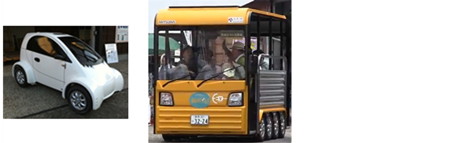
Figure 1. Target electric vehicles.

Figure 2. Configuration of the power supply system.
charging circuit model are explained.
3.1. Constant Current and Constant Voltage Charging Modes
When charging an array of LICs or LIBs, the constant current (CC) and constant voltage (CV) charging modes are used [10] . The CC mode is useful for actually charging the array, and the CV mode is necessary for balancing the state-of-charges (SoCs) for each LIC or LIB. A model battery management system has already been reported [3] [11] , but no models have yet been reported that assume a CC and CV charging circuit.
3.2. Previous Supercapacitor Models
Some battery models have already been proposed for MBD applications in EVs [12] -[15] . As for capacitors, an electric double-layer capacitor (EDLC) model has been reported [6] [16] . Moreover, a general supercapacitor model for circuit simulation [17] and a behavioral model of supercapacitors [18] have been previously discussed.
Here the implementation of supercapacitors is mainly discussed for use with LICs and EDLCs. The simplest EDLC model is the RC serial model, where a resistor (R) and a capacitor (C) are connected in a series called an “RC connection” [19] . A three-branch model, which connects three branches of RC serial connections in parallel, has been studied [20] and is called the Zubieta model; it includes a capacitor that represents voltage dependency. Another type of model comprises three RC serial connections with two serial switches that operate according to time-variant responses [16] .
The three-branch model for EDLC separates the different time constants represented by different branches. One such model has been developed [19] . For accuracy, an EDLC model gradually becomes complicated by the addition of RC serial connections that correspond to EDLC characteristics; however, it has been insisted that the effects of adding a capacitor are very small in terms of improving the model’s performance [21] . Therefore, we can conclude that many previous EDLC models implement RC serial connections and are modified to adjust the charging or discharging behavior of the model to actual measured behavior through the addition of RC serial connections.
LICs are relatively new devices, and only few studies discuss the LIC models. Previously proposed LIC models can be grouped into two categories. The first type of model [22] is an extension of the Zubieta-model for EDLC and is constructed with a set of three variable capacitors, a set of two variable resistors (for representing the charging and discharging behavior), and one parallel variable resistor. Here the values of these variable devices are determined according to the corresponding look-up tables that are constructed from their measured results; therefore, this type of model is very specific to the device used. The contents of a look-up table are the current, state-of-charge (SoC), temperature, charging/discharging cycle (life cycle), and so forth; a look-up table for variable elements is ordered from two-dimensional to four-dimensional. To complete a look-up table, large-scale special measuring apparatuses and very careful measurements are needed. In contrast, this type of model does not include a resistor for each RC serial connection branch, which is a modification of the basic Zubieta-model form. The objective of this modification is to simplify the three-branch model for EDLC. Here it is estimated that this simplification is tied to the fact that an LIC has less voltage dependency than does an EDLC.
The second type of model [23] is constructed with countless RC series connections, and the values of R and C are parameterized by three parameters (Ri: resistance, C: capacitance, and τ: time constant), which are approximated by third- or fourth-power polynomial functions of voltage. This model comes from the first branch in the EDLC model [24] . The apparent reason for only considering the first branch appears to be that an LIC’s linear dependency on the discharging current is stronger than that of an EDLC. The impedance of an LIC, including frequency characteristics, can be calculated from these three parameters, and parameter identification in this model is comparatively simple. However, as is described later, an LIC has a capacitive dependence with the discharging current, making it likely that current dependency―not voltage dependency―would be considered in its modeling.
3.3. Suggested LIC Model
The objective of LIC modeling in this paper is to work out the functional design of the charging/discharging behaviors of an LIC, based on the MBD method. Therefore, a simple and practical LIC model is required. Detailed characteristics, such as temperature and life-cycle characteristics, are not required in the functional design. Usually, data sheets published by LIC manufacturers are available and sufficient for the required modeling. For example, the generic LIC manufactured by Taiyo Yuden Co., Ltd. and its data sheets, which were published as a report [25] , are used in these experiments. The descriptions and the figure, “Discharge Rate Characteristics,” show its high linearity on the given voltage and its general nonlinearity on the discharging current. Furthermore, from the initial IR drop behavior during discharge and the figure captioned “Self Discharge Characteristics” in the data sheets, we see that the LIC’s potential can be kept at over 95% after several thousands of hours. From these observations, a simple LIC model that includes a variable capacity with a current dependency is proposed.
The LIC model suggested in this paper is shown in Figure 3. Functional and timing behaviors are required in this modeling, rather than detailed electrical behaviors. Therefore, this model consists of comparatively large, parallel resistance and the RC connection mentioned above. In this paper, thermal behaviors are not included in the model. The RC connection is shown as the serial connection of “Serial R” and a variable capacitor “C”. The “Serial R” is an equivalent serial resistance (ESR) and “C” is the capacitance of the LIC, which has a dependency on the discharging current. Therefore, a “Current Measurement” block is inserted between “Serial R” and “C” and, from the measured current, the “Lookup Table” finds the corresponding capacitance and then dynamically sets it to “C”. The “Low Pass Filter” with the time constant 1.0 [s] is inserted between the “Current Mea-

Figure 3. Suggested LIC model.
surement” block and the “Lookup Table” to avoid the excessive instantaneous change of the capacitance of “C.” As described above, this model is very simple and its efficiency is proven in the experiments described below.
3.4. The Charging and Discharging Controller Model
As mentioned in Section 3.1, both the CC and CV charging modes are needed to charge LICs. A model for the electrical circuit and controller, implementing the CC and CV modes, is shown in Figure 4. This proposed model consists of a charging and discharging circuit and a controller. The controller changes between modes― such as charging/discharging, preliminary charging, CC charging, and CV charging―by using V1 and V2, which are the LIC’s voltages. Moreover, the controller also checks the LIC’s over-discharging. In each of these modes, V1 and V2 are compared with the specified input voltages, such as (Vp1, Vp2), (Vc1, Vc2), (Vv1, Vv2), and (Vd1, Vd2). The controller can be implemented by either an electrical circuit or an embedded system. In Figure 4, two LICs can be connected in order to test the balance of the charging and discharging of the LIC array.
The controller’s functions can be described as follows. When V1 and V2 are greater than the threshold voltage of the preliminary charging mode (Vp1), the switch (SW1) is off in order to terminate that mode; however, when either V1 or V2 is less than Vp2, SW1 is on. Similarly, for the CC mode, only SW2 is on or off according to V1 and V2 or according to either V1 or V2. For the CV mode, corresponding to Vi, only the switch SWi + 2 is off (i = 1, 2); otherwise, SW3 and SW4 are on. SW5 is used to prevent over-discharging.
4. Experimental Results
This section describes the experiments that were done to check the controller’s functions and to evaluate the performance of the proposed models when an actual LIC is used. The parameter values are shown in Table 1. The proposed models are implemented in MATLAB/Simulink based on a simulation-driven product design paradigm. The simulation results―that is, the models’ behaviors―are then compared with the behaviors of the actual LIC and of the constructed charging and discharging electrical circuit.
4.1. The LIC Used in the Experiments
A photograph of the LIC used in the experiment and its specifications [26] are shown in Figure 5. This type of LIC, with a large capacitance, is currently used in many applications. Its average capacitance is 200 [F] and its ESR in Figure 3 is 50 [mΩ]. Its parallel resistance is very large; that is, the LIC’s voltage is kept at more than

Figure 4. Charging and discharging system model.
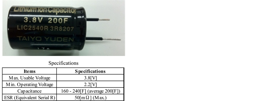
Figure 5. The LIC used in the experiments.

Table 1. Parameter values for the experiments.
95[%] of its initial voltage after more than 3000 [Hrs]. The parallel resistance has no effect on the charging/discharging characteristics as long as the observation time is kept within several minutes rather than several thousands of hours. Therefore, the parallel resistance is roughly estimated as 6 [MΩ] based on the observation that the self-discharge would be only a 0.2[%] decrease at 800 [Hrs] from 3000 [Hr] to 3800 [Hr].
4.2. Charger Model Implementation in Simulink
The proposed charging and discharging system model is shown in Figure 4. The Simulink implementation of the charging operation of that system is shown in Figure 6. As shown in Figure 6, one capacitor socket is unnecessary, in which case SW4 is not included. The LIC model shown in Figure 3 is embedded around the center of Figure 6. The charging operation is performed by the switching operations described in Figure 4. In the preliminary charging mode, the power is supplied via SW1. In the CC and CV modes, the power is supplied via SW2, and in the CV mode, the switching operations of SW3 are repeated according to the LIC’s voltage.
4.3. Discharger Model Implementation in Simulink
The discharging operation in Figure 4 is implemented in Simulink as shown in Figure 7. LIC’s time-variant voltage can be measured by the “simout” terminal block that is circled by “Voltage of LIC”. The “Vd2” block shows the lowest operating voltage, which means that the discharging operation is activated by turning off SW5, as described in Figure 4.
4.4. Charger and Discharger Model Implementation by Electrical Circuit
In order to compare the functions and performances of the proposed LIC model and its charging and discharging modes, the actual electrical circuit is implemented as shown in Figure 8. The size of the printed wiring board is 310 × 228 mm2. The controller is implemented by using the logic circuit; it can also be configured by combining a commonly used microcomputer and embedded software.
4.5. Evaluations
Evaluation results of the proposed LIC model compared with an actual LIC device are provided in this section. First, evaluation measurements are described; the charging and discharging profile comparisons are then given.
4.5.1. Objective and Measurement
The objective of the comparison is to evaluate the accuracy of the proposed LIC model (which is specified in Section 3.3) by comparing it against an actual LIC device. The goal is not to numerically match the voltages of the LIC model to those of the actual LIC device because no detailed electrical parasitic or noise is included in the suggested simulation and, moreover, variability exists within actual LIC devices. Therefore, the correlation factor of voltage profiles between the proposed LIC model and the actual LIC device is used as our standard of measurement―not the root mean square error.
4.5.2. Discharging Profiles
The discharging profiles of the model and actual LIC device are compared; those results are shown in Figure 9. Here, an electronic load device is connected as shown in Figure 8. The discharging profiles are compared in cases where the discharging currents are 0.3, 0.5, 1.0, 2.0, 3.0, 4.0, and 5.0 [A]. From the measured results, LIC’s high linearity on the voltage can be observed. The slope of each voltage decreases, as shown in Figure 9, corresponding to the actual capacitance; the capacitance Cd can then be obtained by linear approximation using the following equation.

Here, Cd is the discharging capacitance, Id is the discharging current, ∆t is the discharging time, and ∆V is the decrease of the voltage.
In Table 2, the calculated discharging capacitances are listed. The discharging capacitance has non-linearity with respect to the discharging current. These discharging capacitances are written in the “Lookup Table” in Figure 3, and the simulated discharging profiles are shown as dashed lines in Figure 9.

Figure 6. Charging circuit model in Simulink.

Figure 7. Discharging circuit model in Simulink.

Figure 8. Electrical circuit implementation of the charging and discharging circuit.

Figure 9. Discharging profile.
The correlation factors between the measured and simulated discharging profiles are also shown in Table 2. In each case, the correlation factor is very close to 1, the maximum difference is 0.0009, and therefore, the accuracies of the discharging profiles are very high.
4.5.3. Charging Profiles
The measured and simulated results of the charging profiles are shown in Figure 10. The parameters used in this simulation are listed in Table 3. On the printed wiring board, the voltage parameters are set by adjusting the volumes of the variable resistances. The values of Vp1, Vp2, Vc1, and Vv1 are measured by voltage meters. In Figure 10, the blue line is the measured profile and the red line is the simulated profile using the estimated capacitance C = 231.87 [F], which was achieved through the interpolation. The green dashed line shows the simulated profile with C = 200.00 [F] for comparison. From this figure, it is concluded that the simulation result with C = 200.00 [F] has a comparatively faster change from preliminary charging to CC charging modes and also has a steeper gradient of slope in the CC charging mode than in the measured result.
Table 2. Capacitances and correlation factors of discharging/charging profiles.
Table 3. Parameters used in the simulation.

Figure 10. Charging profiles.
As mentioned in Section 3.1, LIC charging must conform to the CC and CV modes as well as to preliminary charging. From this perspective, the simulated results of the proposed model are very close to the measured results, and the correlation factor between those voltage profiles is 0.9986, which is very close to 1. The effect of ESR can be recognized in the rapid increase of voltage at 112 [sec] and in the rapid decrease of voltage at 154 [sec].
In the actual CV mode, LIC’s voltage increases gradually because of the direct feedback control of the LIC’s monitored voltage; however, the simulated voltage of the proposed LIC model holds almost constant voltage once the CC mode ends. This decline is caused by the feedback control mechanism in the Simulink operation. The actual feedback control is very fast in the actual electrical circuit. On the other hand, in the Simulink implementation, the feedback is not direct and is always effective after one unit delay of the simulation cycle. However, for functional design use, it is sufficient to know that the voltage level can be held while in the CV mode.
From these evaluation results, the proposed LIC model can be practically used for functional designs in some applications that are based on the MBD method―such as HESS. The actual functional design of HESS will be utilized for electric vehicle development in the near future.
5. Conclusion
A new LIC model is proposed. The model is very simple, and its accuracy for charging and discharging functions is verified against an actual LIC device with 200 [F]. The correlation factors between the proposed model and the actual device are 0.9986 in the charging mode and within the range of [0.9991, 0.9997] in the discharging mode with various loads. The proposed LIC model, its charger model, and its discharger model can actually be used to model HESS, which is based on the MBD method. In future work, a HESS design or developments using the suggested LIC model within the MBD framework should be incorporated into electric vehicle designs in combination with a motor controller and so forth.
Acknowledgements
The authors express their sincere appreciations to Mr. Isao Oobuchi, CEO, at Daien Co., Ltd., for designing the charging and discharging electrical circuit.
Cite this paper
KyojiNakajo,ShinjiAoki,TakashiYatsuda,ShujiTakahashi,KazuhiroMotegi,YasuhiroKobayashi,YoichiShiraishi, (2016) Modeling of a Lithium-Ion Capacitor and Its Charging and Discharging Circuit in a Model-Based Design. Circuits and Systems,07,11-22. doi: 10.4236/cs.2016.71002
References
- 1. Park, S., Kim, Y. and Chang, N. (2013) Hybrid Energy Storage Systems and Battery Management for Electric Vehicles. Proceedings of the Design Automation Conference, Austin, 29 May 2013-7 June 2013, 1-6.
http://dx.doi.org/10.1145/2463209.2488854 - 2. Medora, N.K. and Kusko, A. (2012) Battery Management for Hybrid Electric Vehicles Using Supercapacitors as a Supplementary Energy Storage System. Proceedings of the Telecommunications Energy Conference, Scottsdale, 30 September 2012-4 October 2012, 1-8.
- 3. Cao, J. and Emadi, A. (2012) A New Battery/UltraCapacitor Hybrid Energy Storage System for Electric, Hybrid, and Plug-In Hybrid Electric Vehicles. IEEE Transactions on Power Electronics, 27, 122-132.
http://dx.doi.org/10.1109/TPEL.2011.2151206 - 4. IEC 61508-3 (1997) Functional Safety of Electrical/Electronic/Programmable Electronic Safety-Related Systems Part 3: Software Requirements. International Electrotechnical Commission 61508-3 Version 12.0.
- 5. Kubo, T. (2014) The Ins and Outs of MBD. SEC Seminar 2014/03/12. (In Japanese).
http://sec.ipa.go.jp/users/seminar/seminar_tokyo_20140312-03.pdf - 6. Nagaoka, N., Fujiyama, S., Nonoyama, H. and Ametani, A. (2009) Parameter Estimation of a Nonlinear EDLC Model for ENMTP Simulation. Proceedings of the International Conference on Power Systems Transients, Kyoto, 3-6 June 2009, 1-6.
- 7. Goswami, D., Lukasiewycz, M., Kauer, M., Steinhorst, S., Masrur, A., Chakraborty, S. and Ramesh, S. (2013) Model-Based Development and Verification of Control Software for Electric Vehicles. Proceedings of the Design Automation Conference, Austin, May 29 2013-June 7 2013, 1-9.
- 8. Kobayashi, Y., Tatsuno, S., Takahashi, S., Motegi, K. and Shiraishi, Y. (2014) A DSP-Based Embedded System for Hybrid Energy Storage System Consisting of Capacitor and Battery. Proceedings of 57th Joint Conference on Automatic Control, Ikaho, 10-12 November 2014, 1294-1299 (in Japanese).
- 9. Shimamura, Y., Shiraishi, Y., Motegi, K., Kobayashi, Y., Koga, T., Nakamoto, E., Uchida, J. and Todoh, T. (2014) A Motor Modelling for Micro-Mobility by Using Model Based Development method. Proceedings of 57th Joint Conference on Automatic Control, Ikaho, 10-12 November 2014, 1311-1316 (in Japanese).
- 10. Sen, C. and Kar, N.C. (2009) Battery Pack Modeling for the Analysis of Battery Management System of a Hybrid Electric Vehicle. Proceedings of the Vehicle Power and Propulsion Conference, Dearborn, 7-10 September 2009, 207-212.
http://dx.doi.org/10.1109/vppc.2009.5289848 - 11. Bonfiglio, C. and Roessler, W. (2009) A Cost Optimized Battery Management System with Active Cell Balancing for lithium Ion Battery Stacks. Proceedings of the Vehicle Power and Propulsion Conference, Dearborn, 7-10 September 2009, 203-309.
http://dx.doi.org/10.1109/vppc.2009.5289837 - 12. Kroeze, R.C. and Krein, P.T.R. (2008) Electrical Battery Model for Use in Dynamic Electric Vehicle Simulations. Proceedings of the IEEE Power Electronics Specialists Conference, Rhodes, 15-19 June 2008, 1336-1342.
http://dx.doi.org/10.1109/pesc.2008.4592119 - 13. Moss, P.L., Au, G., Plicht, E.J. and Zheng, J.P. (2009) Investigation of Solid Electrolyte Interfacial Layer Development during Continuous Cycling Using AC Impedance Spectra and Micro-Structural Analysis. Journal of Power Sources, 189, 66-71.
http://dx.doi.org/10.1016/j.jpowsour.2008.11.048 - 14. He, H., Xiong, R. and Fan, J. (2011) Evaluation of Lithium-Ion Battery Equivalent Circuit Models for State of Charge Estimation by an Experimental Approach. Energies, 4, 582-598.
http://dx.doi.org/10.3390/en4040582 - 15. Buller, S., Thele, M., De Doncker, R.W. and Karden, E. (2005) Impedance-Based Simulation Models of Supercapacitors and Li-Ion Batteries for Power Electronic Applications. IEEE Transactions on Industry Applications, 41, 742-747.
http://dx.doi.org/10.1109/TIA.2005.847280 - 16. Yamada, T., Nakamura, K., Yamashiro, S., Sasaki, M. and Araki, S. (2002) On the Electric Characteristics of High-Power Density Electric Double Layer Capacitor. Proceedings of the International Conference on Electrical Engineering, Jeju Island, 7-11 July 2002, 425-430.
- 17. Farcas, C., Petreus, D., Ciocan, I. and Palaghita, N. (2009) Modeling and Simulation of Supercapacitors. Proceedings of the 15th International Symposium for Design and Technology of Electronics Packages, Gyula, 17-20 September 2009, 195-200.
http://dx.doi.org/10.1109/siitme.2009.5407373 - 18. Camara, M.B., Gualous, H. and Dakyo, B. (2011) Supercapacitor Modeling and Integration in Transport Applications. Proceedings of the Industry Applications Society Annual Meeting (IAS), Orlando, 9-13 October 2011, 1-7.
http://dx.doi.org/10.1109/ias.2011.6074422 - 19. Cheng, Y., Wei, L., Shen, X.J. and Liang, H.Q. (2009) Study of Supercapacitor in the Application of Power Electronics. WSEAS Transactions on Circuits and Systems, 8, 508-517.
- 20. Zubieta, L. and Bonert, R. (2000) Characterization of Double-Layer Capacitors for Power Electronics Applications. IEEE Transactions on Industry Applications, 36, 199-205.
http://dx.doi.org/10.1109/28.821816 - 21. Johansson, P. and Andersson, B. (2008) Comparison of Simulation Programs for Supercapacitor Modelling. Master’s Thesis, Chalmers University of Technology, Gothenburg.
- 22. Omar, N., Daowd, M., Hegazy, O., Al Sakka, M., Coosemans, T., Van den Bossche, P. and Van Mierloa, J. (2012) Assessment of Lithium-Ion Capacitor for Using in Battery Electric Vehicle and Hybrid Electric Vehicle Applications. Electrochimica Acta, 86, 305-315.
http://dx.doi.org/10.1016/j.electacta.2012.03.026 - 23. Barcellona, S., Flavio, F., Iannuzzi, D. and Piegari, L. (2014) Modeling and Parameter Identification of Lithium-Ion Capacitor Modules. IEEE Transactions on Sustainable Energy, 5, 785-794.
- 24. Musolino, V. and Piegari, L. (2013) New Full-Frequency-Range Supercapacitor Model with Easy Identification Procedure. IEEE Transactions on Industrial Electronics, 60, 112-120.
http://dx.doi.org/10.1109/TIE.2012.2187412 - 25. TAIYO YUDEN Navigator (2015) The Use of PAS Capacitors/Lithium Capacitors for Adapting to Diversification of Energy Supply. Volume 4, Special Topics 1, 1-9.
http://www.yuden.co.jp/productdata/navigator/en/004/E-SP1_101013.pdf - 26. LIC2540R3R8207 Datasheet.
http://www.datasheetlib.com/datasheet/142803/lic2540r3r8207_taiyo-yuden.html