Journal of Modern Physics
Vol.4 No.9(2013), Article ID:36561,6 pages DOI:10.4236/jmp.2013.49156
TE Modal Dispersion in Dielectric Slab Waveguide with Lossy Left-Handed Metamaterial
1Department of Physics, Al-Azhar University, Gaza, Palestine
2Department of Physics, University of Dayton, Dayton, USA
Email: hashour1@udayton.edu, hahsour@alazhar.edu.ps
Copyright © 2013 Hassan S. Ashour. This is an open access article distributed under the Creative Commons Attribution License, which permits unrestricted use, distribution, and reproduction in any medium, provided the original work is properly cited.
Received June 28, 2013; revised July 29, 2013; accepted August 23, 2013
Keywords: Dispersion Relation; Left Handed Material LHM; Power Confinement; TE Surface Waves
ABSTRACT
In this work, we derived the modal dispersion relation for TEm modes for a symmetric slab waveguide constructed from SiO2 dielectric guiding core material with lossy left-handed material (LHM) as cladding and substrate, and the power confinement factor. The dispersion relations and the power confinement factor were numerically solved for a given set of parameters: allowed frequency range; core’s thicknesses; and TEm mode order. We found that the real part of the effective refractive index decreased with thickness and frequency increase. Moreover, the imaginary part (extinction coefficient) of the effective refractive index has very small values for all thickness in the frequency ranges, which means the waveguide structure is transparent for the used frequencies. The waveguide structure offers good guiding power for all thickness in the frequency range with low power attenuation. The real part of the effective refractive index increases with the increase of mode order, and the power confinement factor decreases with the increase of mode order.
1. Introduction
Metamaterials are unlike conventional materials, which gain their properties from their inherent composition of atoms and molecules. Metamaterial changed our perspective to this concept by replacing the molecules with manmade structures that might have dimensions of nanometers for visible light (nanorods) or in the case of GHz radiation that may be as large as a few millimeters (Split Rings Resonator SRR), but still much less than the wavelength [1]. Thus, the properties are engineered through structure rather than through chemical composition. These meta materials grasped great attention of many researchers’ worldwide, because of the peculiar characteristics and novel devices which can be built upon. Interest is focused on the propagation of electromagnetic waves in artificial materials, and particularly on materials with negative index of refraction: materials which are designed to exhibit both negative permeability and permittivity over predetermined range of frequencies [2]. In this class of materials, the electric field vector E, the magnetic field vector H, and the wave vector k form a left-hand orthogonal set [3,4], because they are called left-handed materials (LHM). A group of researchers at the University of San Diego were able to demonstrate that those materials exhibit both negative dielectric permitivity and magnetic permeability simultaneously over a certain range of frequencies [5]. It was the first time that Veselago’s prediction [6] in his pioneer paper that electromagnetic propagation in an isotropic medium with negative dielectric permittivity  and negative permeability
  could exhibit unusual properties was realized. Those recent demonstrations on the existence of the LHM resulted in a wide-open to unique possibilities in the design of a novel type of device based on electromagnetic wave propagation in those materials, but in a non-conventional way. As most the communication devices include dielectric materials, which motivated us to investigate the propagation of
  modes in a waveguide structure made of dielectric core with thick cladding and substrate layers of left handed material (LHM), this might have a potential applications in fabricating antenna, microstrips, and couplers, since Meta materials are used in fabricating Transmission lines, Microstrip Resonators, wave division multiplexors (WDM), Couplers, Resonators, and Antennas [7-13]. This paper is organized as follows: in Section 2, we derive the TEm modal dispersion relation in lossy LHM-Dielectric structure and the power confinement factor; Section 3 is devoted for discusses the numerical results; Section 4 is solely devoted to the conclusion.
2. Theory
2.1. TE Modes Dispersion Relation
We briefly outline the derivation of the dispersion relation for TEm mode in the proposed waveguide structure [14,15]. The dispersion relation for TEm modes propagation in the  with complex propagation wave constant
  is represented in the form
 , where
 , k is the effective wave index in each layer, and
  is the free space wave number which equals
 , where
  is the velocity of light, and
  is the applied angular frequency. Figure 1 shows the geometry and coordinates of the structure under investigation. The structure, shown in Figure 1, is an isotropic dielectric material core,
  surrounded by thick cladding and substrate layers of lossy left-handed material. The electromagnetic field components are,
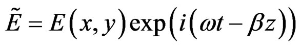 (1)
(1)
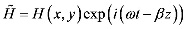 (2)
(2)
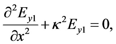
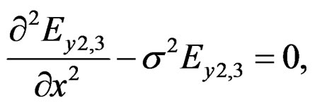
Substitution of Equations (1) and (2) into Maxwell’s equation yields the following linear differential equations for the core and cladding respectively are given by
 (3)
(3)
and
 (4)
(4)
Where  and
and 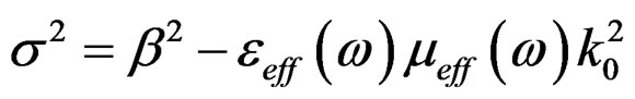 are the wavenumbers in the core and cladding respectively. Where
  is the electric field in the guiding core, and
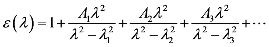
  is the frequency dependent electric permittivity, which can be obtained from Sellmeier dispersion relationship, which is given by [16]
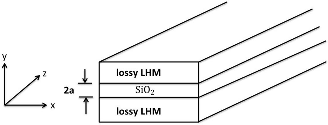
Figure 1. Geometrical structure of the slab waveguide. The upper and lower layers (cladding and substrate) are made from lossy left handed metamaterial, and the core is dielectric material (SiO2) fused silica.
 (5)
(5)
Where  is a constant, and
  are called Sellmeier coefficients, and have the following values for
  fused silica:
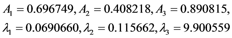 .
.
Where,  and
and  are the effective dielectric permittivity and permeability respectively, and they are given by the well-known Drude model [17-21]
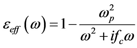 (6)
(6)
and
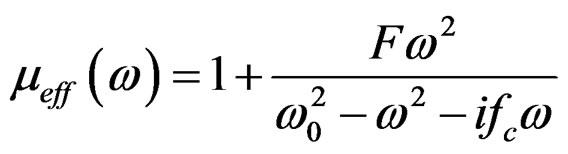 (7)
(7)
Where  is the plasma angular frequency of the wires,
  is the operating angular frequency,
  is the structural factor (sometimes is called the filling fraction of the material) which depends on the characteristics of the embedded split rings resonators
  in host material,
  is the damping frequency (is the collision frequency of the electrons), and
  is the resonant frequency of the split ring resonators. Besides that, the magnetic field components can be written as
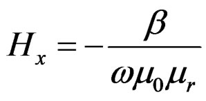 (8)
(8)
and
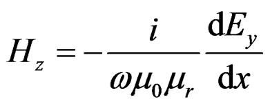 (9)
(9)
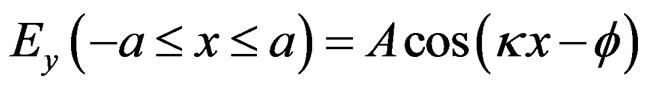
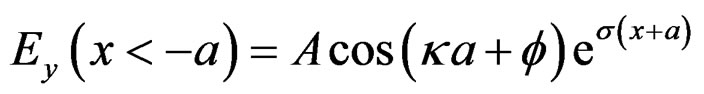
We consider the slab waveguide with uniform refractive-index profile in the core. We use the fact that the guided electromagnetic fields are confined in the core and exponentially decay in the cladding, the electric field distribution in the core and cladding is
 (10.1)
 (10.2)
 (10.3)
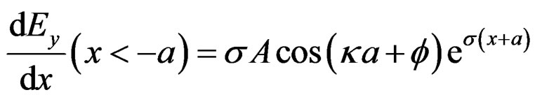
The electric field components  in Equation (10) is continuous at the interface between the core and the cladding at
 . Neglecting the terms independent of
 , the boundary condition for
  is treated by the continuity condition of
  as
as
 (11.1)
 (11.2)
 (11.3)
From the condition that the  are continuous at
 , we obtain the following
 (12.1)
 (12.2)
Eliminating A from Equation (12), and rearranging we have the dispersion relation for  modes, that is
 (13)
(13)
Where ,
,  ,
,  , and
, and  is the order of the
  mode.
mode.
2.2. Confinement Factor
The power flow is the real part of the integral of the complex Poynting vector over the waveguide cross section, that is
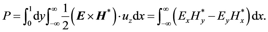 (14)
(14)
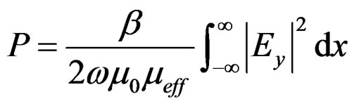
For  wave we rewrite Equation (14) using Equations (8) and (9), as
 (15)
(15)
Substituting Equation (10) in Equation (15), we have the power flow in each layer, that is
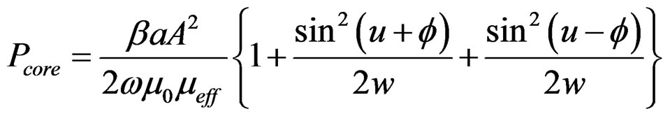 (16.1)
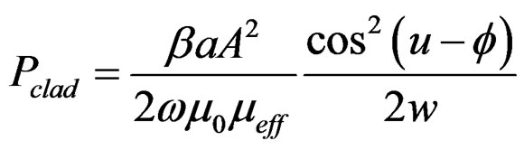 (16.2)
 (16.3)
Where  and
and  are the power in the core, cladding, core, and substrate. The power confinement factor in the core is defined and the power flow in the core to the total power flow in the waveguide. Thus, the power confinement factor can be calculated using Equation (18), that is
 (17)
(17)
Where  is the total power flow in the waveguide structure.
3. Numerical Results and Discussion
The dispersion relation, Equation (13), numerically solved to find the complex effective wave index  as a function of the angular frequency
  in the allowed frequency spectrum for different dielectric constants, for dielectric film thicknesses
 , and mode order. The power confinement factor for the structure under investigation has been investigated for the film thicknesses and mode order. The parameters of the lossy LHM have been theoretically adjusted to have negative permittivity and negative permeability in the frequency range which lies between 10.5 ~ 15.5 GHz. The parameters were used in carrying out the numerical calculations are: the plasma frequency ωp/2π = 10.95 GHz,
  is the damping frequency = 0.5 GHz, and the electrons resonant frequency ω0 = 8 GHz, and the structure factor F = 0.8. In Figure 2, we plot the real part of the effective refractive index,
  , for
, for  mode versus the operating frequency range at different dielectric SiO2 core thickness. It is noticed that the real part of the effective refractive index attains small index values, which means the phase front variation upon propagation through this waveguide structure is small. Besides that, the real part of the effective refractive index decreases smoothly with frequency increase with negative slope. The negative slope indicates that the overall effect of structure behaves like left handed material (LHM), since the slope of the dispersion relation represents the group velocity [22,23]. Figure 2 also shows that, as the core’s thickness increase the real part of the effective refractive index decrease. The upper dotted curve is for a = 50 μm and the lowest solid line curve is for a = 150 μm.
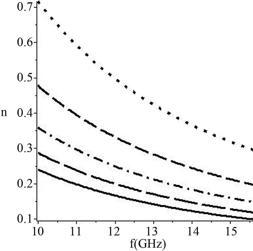
Figure 2. The real part of the effective refractive index versus the angular frequency for different dielectric core thicknesses. Note: a = 50 μm (dotted), 75 μm (dashed), 100 μm (dot dash), 125 μm (long dash), and 150 μm (solid).
In Figure 3, we plot the imaginary part of the effective refractive index (extinction coefficient), γ, for TE0 mode versus the operating frequency range at different dielectric SiO2 core thickness. It is noticed that the extinction coefficient attains very small negative values, which means the structure is transparent for the allowed frequency spectrum. The value of the extinction coefficient increases with core’s thickness increase. However, the extinction coefficient decreases with frequency increase.
In Figure 4, we plot the power confinement factor for TE0 mode (Equation (17)) versus the allowed frequency range for different core’s thicknesses. Figure 4 shows that at lower frequencies the power confinement factor is better for small thickness and gets lower confinement as the core’s thickness increases. However, this behavior
Figure 3. The extinction coefficient versus the angular frequency for different dielectric core thicknesses Note: a = 50 μm (dotted), 75 μm (dashed), 100 μm (dot dash), 125 μm (long dash), and 150 μm (solid).
Figure 4. The power confinement factor versus the angular frequency for different dielectric core thicknesses.Note: a = 50 μm (dotted), 75 μm (dashed), 100 μm (dot dash), 125 μm (long dash), and 150 μm (solid).
Figure 5. The power attenuation versus the angular frequency for different dielectric core thicknesses Note: a = 50 μm (dotted), 75 μm (dashed), 100 μm (dot dash), 125 μm (long dash), and 150 μm (solid).
flips at approximately ω = 12 GHz and the structure guides the power better for the thicker core than the slim one. But the overall performance of the waveguide structure is good enough to be used in any possible application. This implies the structure guides the power through the core more than wasting it in the cladding, and this conclusion can also be seen from Figure 5.
In Figure 5, we plotted the power attenuation for  mode (the imaginary part of Equations (17)) versus frequency for different core’s thicknesses. In Figure 5 shows that the power attenuation for
  mode increases with dielectric core’s thickness increase, but for each core’s thickness the power attenuation decreases with frequency increase.
In Figure 6, we explore the effect of the mode order on the real part of the effective refractive index. It is worth to notice that the real part of the effective refractive index increases with mode order increase, which means the higher the order of the mode the wave front will suffer more phase variations upon propagation in this structure. Figure 6 shows that the real part of the effective refractive index for  mode (solid curve) is the lowest, and for
  mode (long dash curve) is highest in value. For all modes the real part of the effective refractive index decreases with operating frequency increase with negative slope, which implies that the structure behaves like left handed material (LHM) for all
  modes.
In Figure 7, we plot the power confinement factor versus the allowed frequency spectrum for different modes at core’s thickness a = 100 μm. Figure 7 indicated that the power confinement increases with mode order increase. Besides that the power confinement factor slightly decreases over the allowed operating frequency, and it could be considered as a constant for a given mode.
Figure 6. The real part of the effective refractive index for TEm modes versus the angular frequency for mode order. Note: m = 0 (solid), m = 1 (dashed), m = 2 (dot dash), m = 3 (long dash), and core’s thickness = 100 μm.

Figure 7. The power confinement factor for TEm modes versus the angular frequency for mode orders. Note: m = 0 (solid), m = 1 (dashed), m = 2 (dot dash), m = 3 (long dash), and core’s thickness = 100 μm.
4. Conclusion
We derived the modal dispersion relation for TEm modes for symmetric slab waveguide constructed from  dielectric guiding core material with cladding and substrate made of lossy left-handed material (LHM), and the power confinement factor. The numerical solutions showed that the real part of the effective refractive index decreased with thickness and frequency increase. Moreover, the imaginary part (extinction or attenuation coefficient) of the effective refractive index has very small values for all thickness in the frequency ranges, which means the waveguide structure is transparent for the used frequencies. The waveguide structure offers good guiding for all thickness in the frequency range with low power attenuation. The real part of the effective refractive index increases with mode order increase, and the power confinement factor decreases with mode order increase. This waveguide structure is a good candidate for coupling or guiding electromagnetic waves.
REFERENCES
- S. J. Pendry, “Metamaterials and the Control of Electromagnetic Fields,” Conference on Coherence and Quantum Optics, Rochester, 13 June 2007.
- A. I. Ass’ad and H. S. Ashour, Turkish Journal of Physics, Vol. 36, 2012, pp. 207-213.
- R. A. Shelby, D. R. Smith, N. Nasser and S. Shultz, Applied Physics Letters, Vol. 78, 2001, p. 489. doi:10.1063/1.1343489
- J. B. Pendry, Physical Review Letters, Vol. 85, 2000, pp. 3966-3969. doi:10.1103/PhysRevLett.85.3966
- R. A. Shelby, D. R. Smith and S. Schultz, Science, Vol. 292, 2001, pp. 77-79. doi:10.1126/science.1058847
- V. G. Veselago, Soviet Physics Uspekhi, Vol. 10, 1967, pp. 509-514. doi:10.1070/PU1968v010n04ABEH003699
- C. Caloz and T. Itoh, “Application of the Transmission Line Theory of Left-Handed (LH) Materials to the Realization of a Microstrip LH Transmission Line,” 2002 IEEE Antennas and Propagation Society International Symposium, San Antonio, 16-21 June 2002, pp. 412-415.
- C. Caloz and T. Itoh, “Electromagnetic Metamaterials: Transmission Line Theory and Microwave Applications,” IEEE Press and Wiley, New York, 2005. doi:10.1002/0471754323
- C. Caloz and T. Itoh, IEEE Transactions on Antennas Propagation, Vol. 52, 2004, pp. 1159-1166. doi:10.1109/TAP.2004.827249
- T. T. Tang, W. L. Liu, X. J. He and X. Y. Gao, OptikInternational Journal for Light and Electron Optics, Vol. 123, 2012.
- T. T. Tang, Optik-International Journal for Light and Electron Optics, 2013, in Press.
- S. Otto, A. Rennings, C. Caloz, P. Waldow, I. Wolff and T. Itoh, “Composite Right/Left Handed λ-Resonator Ring Antenna for Dual-Frequency Operation,” Proceedings of IEEE AP-S USNC/URSI National Radio Science Meeting, Washington DC, 3-8 July 2005.
- A. Sanada, K. Murakami, I. Awai, H. Kubo, C. Caloz and T. Itoh, “A Planar Zeroth Order Resonator Antenna Using a Left-Handed Transmission Line,” 34th European Microwave Conference, Amsterdam,12-14 October 2004, pp. 1341-1344.
- M. J. Adams, “An Introduction to Optical Waveguides,” John Wiley and Sons, New York, 1981.
- K. Okamoto, “Fundamentals of Optical Waveguides,” Elsevier Inc, Burlington, 2006.
- J. Singh, “Optical Properties of Condensed Matter and Applications,” John Wiley, New York, 2006. doi:10.1002/0470021942
- Y. Chen, P. Fischer and F. Wise, Quantum Electronics and Laser Science Conference, Baltimore, 22-27 May 2005.
- P. Markos and C. Soukoulis, Physical Review E, Vol. 65, 2002, p. 8. doi:10.1103/PhysRevE.65.036622
- I. Shadrivov, S. Morrison and Y. Kivshar, Optics Express, Vol. 14, 2006, p. 9344. doi:10.1364/OE.14.009344
- J. Zhou, N. Eleftherios, E. Koschny, M. Costas and C. Soukoulis, Optics Letters, Vol. 31, 2006, pp. 3620-3622. doi:10.1364/OL.31.003620
- J. Kong, Journal of Electromagnetic Waves and Applications, Vol. 15, 2001, pp. 1319-1320. doi:10.1163/156939301X01200
- A. I. Ass’ad, H. S. Ashour and M. M. Shabat, International Journal of Modern Physics B, Vol. 21, 2007, pp. 1951-1960. doi:10.1142/S0217979207037120
- A. D. Boardman, M. M. Shabat and R. F. Wallis, Journal of Physics D, Vol. 24, 1991, pp. 1702-1707. doi:10.1088/0022-3727/24/10/002