Wireless Engineering and Technology
Vol. 4 No. 1 (2013) , Article ID: 27642 , 8 pages DOI:10.4236/wet.2013.41002
Effect of Partial Ground Plane Removal on the Radiation Characteristics of a Microstrip Antenna
![]()
Department of Electronic Engineering, Kyonggi University, Suwon, South Korea.
Email: hmlee@kyonggi.ac.kr, cws2k2k@gmail.com
Received October 11th, 2012; revised November 16th, 2012; accepted November 29th, 2012
Keywords: Front-to-Back Ratio; Microstrip Antenna; Removed Ground Plane; Soft-Surface; Split Ring Resonator
ABSTRACT
This study presents a new, simple method for reducing the back-lobe radiation of a microstrip antenna (MSA) by a partially removed ground plane of the antenna. The effect of the partial ground plane removal in different configurations on the radiation characteristics of a MSA are investigated numerically. The partial ground plane removal reduces the backlobe radiation of the MSA by suppressing the surface wave diffraction from the edges of the antenna ground plane. For further improving the front-to-back (F/B) ratio of the MSA, a new soft-surface configuration consisting of an array of stand-up split ring resonators (SRRs) are placed on a bare dielectric substrate near the two ground plane edges. Compared to the F/B ratio of a conventional MSA with a full ground plane of the same size, an improved F/B ratio of 9.7 dB has been achieved experimentally for our proposed MSA.
1. Introduction
Microstrip antennas (MSAs) are used in modern communication systems due to its low cost, lightweight, and planar structure. One of the major concerns in practical MSA design is surface wave excitation. When an MSA is fabricated on a substrate, it shows significant performance degradation by surface waves. On a finite ground plane, surface waves propagate until they reach an edge where they reflected back and diffracted by the edges. Particularly when the patch antenna is printed on high dielectric substrates, its back radiation pattern increases owing to surface wave diffraction from the edges of the antenna ground plane. Numerous efforts have been made earlier to reduce the surface waves on an MSA. One approach is to construct an artificial periodic structure such as an electromagnetic band-gap (EBG) [1] or a conventional artificial soft/hard surface [2-5]. Both EBG and soft surfaces can be used to suppress surface wave propagation. The main difference is that soft surfaces exhibit band-gaps only one direction, but they offer the best performance in most applications of antennas. Another approach is to use a micro-machining technology [6], in which part of the substrate beneath the radiating patch is removed to realize a low effective dielectric constant of the substrate. This structure can be used to reduce the surface waves, it involves high fabrication cost. In recent years, methods for reducing the mutual coupling between antennas [7] and enhancing the front-to-back (F/B) ratio of the MSA [8,9] have been investigated. Although the structure reported in [8], can be used to reduce the surface waves, they require a considerable area to form a band-gap. In [9], the broadside gain of an MSA is increased by around 2 dBi by partially removing the substrate surrounding the patch element. However, this method cannot be used to reduce the back-lobe gain. We present a new method for reducing the back radiation of an MSA by employing a partially removed ground plane and soft-surface structures.
2. Effect of the Partial Ground Plane Removal on the Gains of MSA
To investigate the effect of the ground plane size on the radiation characteristics of an MSA, a conventional MSA with a full metallic ground plane that operates in the dominant mode (TM10) at 2.5 GHz is designed.
The simulated peak broadside gain curve of the probe feed MSA with a different size of the ground plane (S mm × S mm) is plotted in Figure 1. This MSA with a size of square patch element (P × P = 18 mm × 18 mm) is designed on the Rogers R3210 substrate (having a relative dielectric constant of 10.2, thickness of 1.27 mm, and loss tangent of 0.0025), and simulations are carried out using CST Microwave Studio. It is observed from Figure 1 that as the size of the ground plane increases from 40 mm to 140 mm, the broadside gain remains around 3.2 dBi, and it subsequently decreases to –1.0 dBi at 210 mm. We choose the length of the ground plane of the MSA as 120 mm.
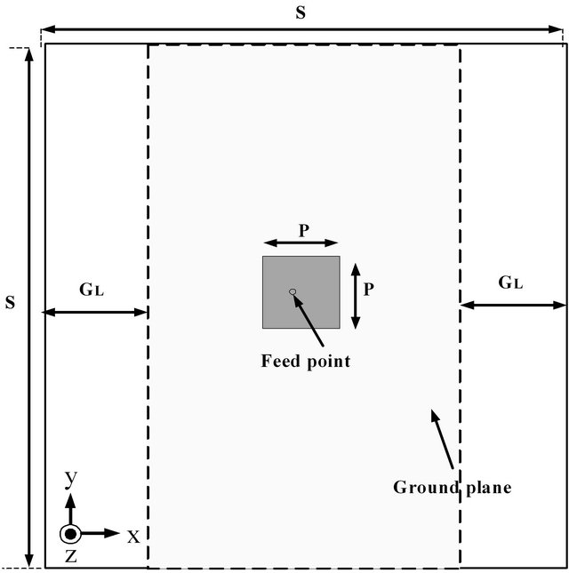
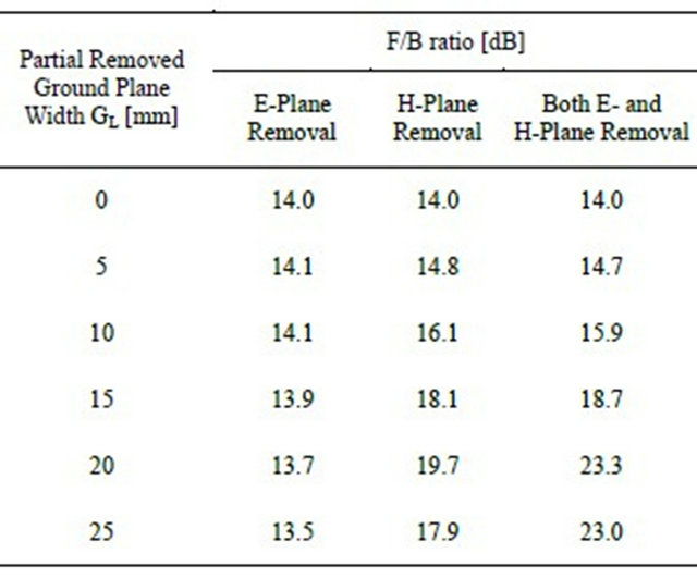
Next, in order to investigate the effect of partial ground plane removal on the F/B ratio of the MSA, some metallic parts of the MSA ground plane with a width of GL is removed, as shown in Figure 2. The simulated F/B ratio curves of the MSA with a different size of the partially removed ground plane are plotted in Figure 3 and summarized in Table 1.
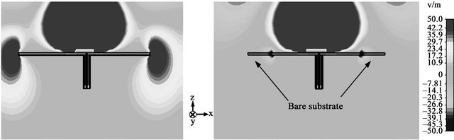
In the back-lobe region radiation pattern of the MSA, the E-plane edge diffraction of surface waves has a much larger contribution to the magnitude than the H-plane edge diffraction [10], and it decreases by reducing the length of the ground plane (H-plane removal). However, in the case of E-plane removal the back-lobe gain (at θ = 180˚) was not improved. As a result, the F/B ratio remains around 14 dB. In the both Eand H-plane removal case, F/B ratio of the MSA was improved significantly as the width of the partially removed ground plane GL increased. It is observed from Figure 3 that as the width of the partially removed ground plane GL increased from 0 to 20 mm, the F/B ratio of the MSA shows 23.1 dB. The F/B ratio of the MSA increases to a maximum at GL = 22.5 mm, with the F/B ratio peak of 23.6 dB. We choose the partially removed ground plane size of the MSA as 75 mm × 75 mm. Figure 4 shows the plot of the simulated normal electric field (Ez) distributions in the Eplane of the MSA with a full ground plane and a partial ground plane removal. In the case of a conventional MSA with a full ground plane, surface waves are diffracted at the end of the ground plane edges, as shown in Figure 4(a).
As a result, the partial ground-plane removal method can reduce the back radiation of the MSA owing to the suppression of surface wave diffraction from the edges of the conventional MSA ground plane. On the other hand, in the case of a MSA with a partial ground plane removal, there are field minima at the ends of the removed ground plane, as shown in Figure 4(b).
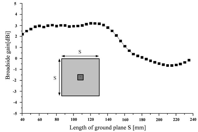
Figure 1. Simulated broadside gain versus the ground plane size S of a conventional MSA.
 (a)
(a)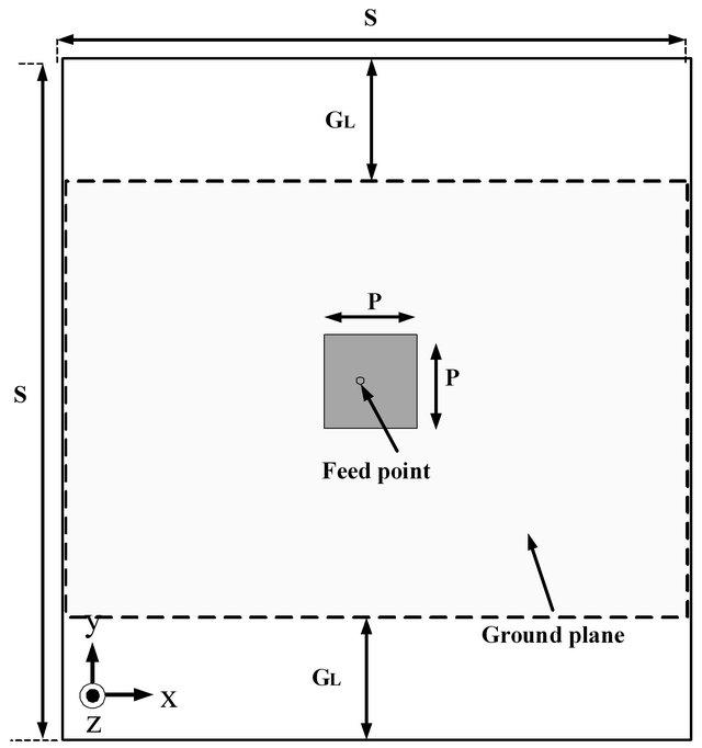 (b)
(b)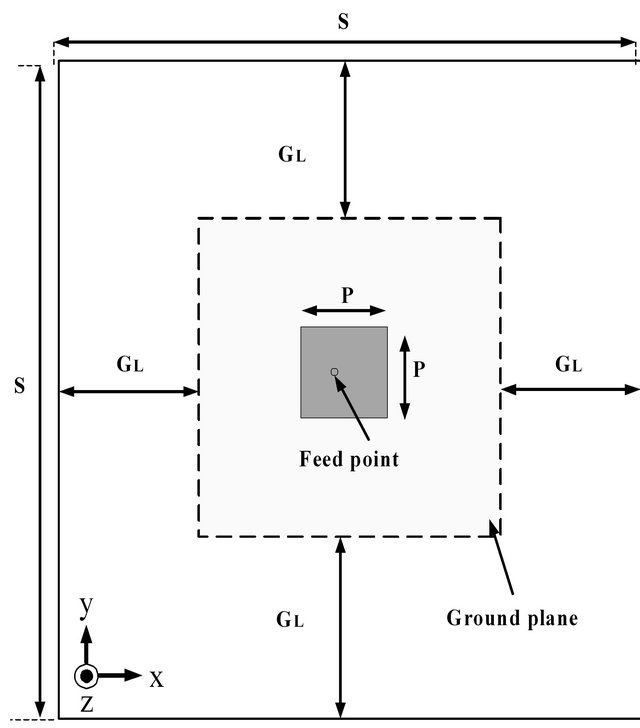 (c)
(c)
Figure 2. Geometry of MSA with different partial ground plane removal width GL: (a) E-plane removal; (b) H-plane removal; (c) Both Eand H-plane removal.
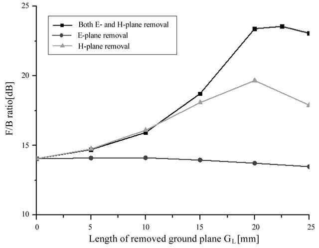
Figure 3. Simulated F/B ratio versus the length of the partially removed ground plane GL.
Table 1. Comparison of simulated F/B ratio for the different partial ground plane removal width GL.
 (a) (b)
Figure 4. Simulated normal electric field (Ez) distributions of the MSA: (a) With a full ground plane; (b) With a partial ground plane removal.
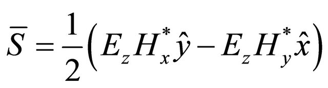
For further improving the F/B ratio of the MSA with a simple soft-surface structure consist of split ring resonators (SRRs), we investigate the field excited near the MSA. Figure 5 shows the plot of the simulated tangential magnetic field component (Hy) distributions within the substrate excited by the MSA. It is observed that the magnitudes of the tangential magnetic field component (Hy) are strongly distributed along the E-plane edge direction of the MSA and decay slowly with an increase in the distance along the y-axis. In contrast, the magnitudes of the tangential magnetic field component (Hy) along the H-plane edge direction of the MSA decay rapidly with an increase in the distance along the x-axis. The complex power density in the vicinity of the MSA on the ground plane can be expressed with the tangential magnetic field components (Hx and Hy), and the normal electric field component (Ez), according to equation as
 (1)
(1)
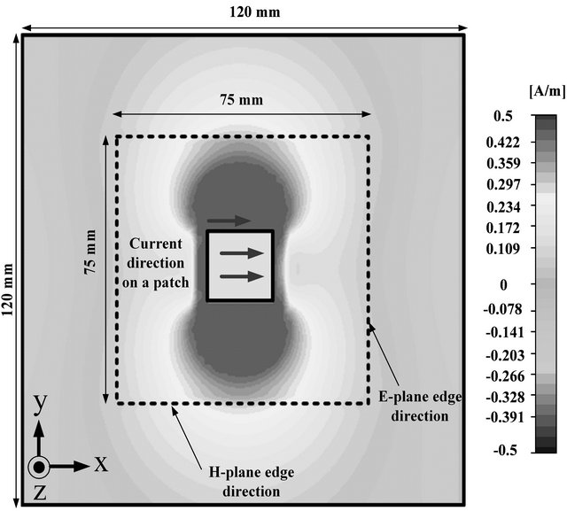
Figure 5. Simulated tangential magnetic field component (Hy) distributions on the MSA.
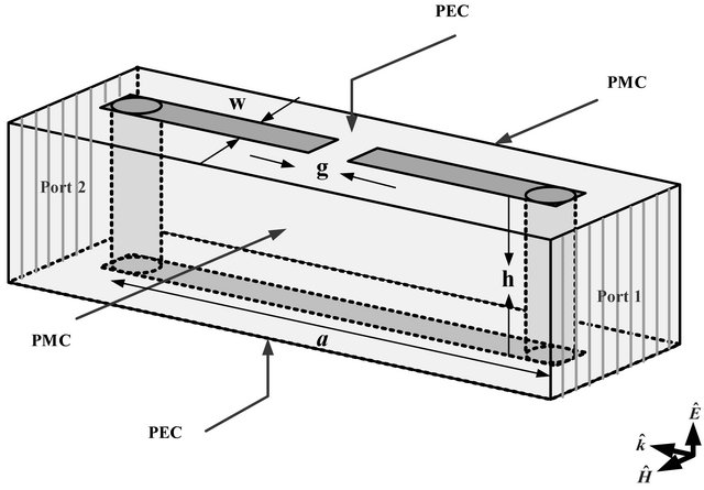
For reducing the ground plane edge diffraction along the two H-plane edges, which account for back radiation of the MSA, we prepared a soft-surface structure consisting of an array of stand-up SRRs. By placing a stand-up SRR near the side of the partially removed ground plane edge, where the magnitudes of the tangential magnetic field component (Hy) are strongly distributed, some parts of the complex power density can be reduced. A schematic of the simulation setup for an optimum stand-up SRR unit cell within a dielectric substrate and the simulated transmission coefficient are shown in Figure 6. As shown in Figure 6, the optimized physical dimensions (in millimeters) of the stand-up SRR are as follows: a = 13.8, w = 0.4, h = 1.27 and g = 0.7. A single SRR consisted of the metal strips and the two metallic via-holes, as shown in Figures 6(a) and (b). The metal used for the metallic SRR patterns is a copper with a conductivity σ = 5.8 × 10⁷ S/m. It was placed within a Rogers R3210 substrate. Computer simulations for one SRR with appropriate boundary conditions are carried out. The perfect electric conductor boundary conditions are applied to the top and bottom walls of the waveguide. Perfect magnetic conductor boundary conditions are applied to the side walls of the waveguide.
A single SRR unit cell is placed inside a waveguide, and a vertically polarized transverse electromagnetic (TEM) wave is incident normally on the front side of port 1, as shown in Figure 6(a).
 (a)
(a)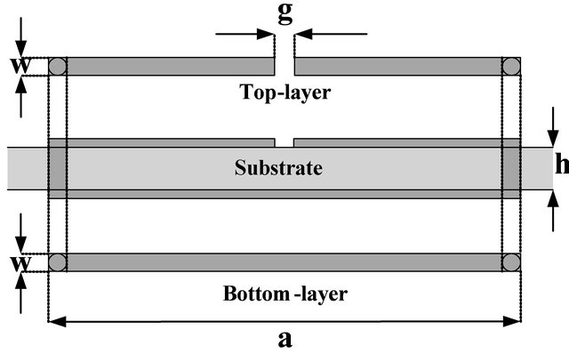 (b)
(b)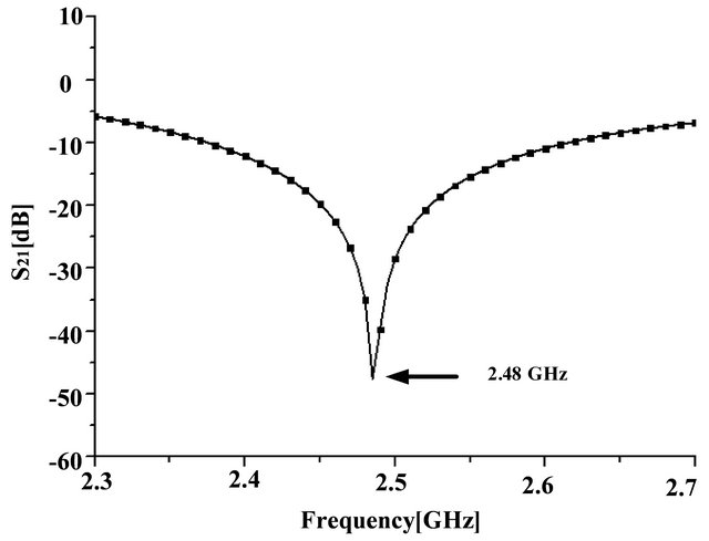 (c)
(c)
Figure 6. (a) Simulation setup for a stand-up SRR; (b) Cross-sectional view of a stand-up SRR in dielectric substrate; (c) Simulated transmission coefficient of a stand-up SRR.
It is well known that incident electromagnetic wave can resonantly couple to the LC resonance of an SRR through either the electric or magnetic field. This occurs either when the electric field is parallel to the side containing the SRR gap or when the magnetic field has a component normal to the plane of the SRR ring. When the incident wave is polarized as indicated in Figure 6(a), the excitation is purely magnetic. The simulated transmission coefficient (S21) of the SRR as a function of the frequency is shown in Figure 6(c). We observe that the magnitudes of the transmission coefficients of a stand-up SRR are very low at the fundamental resonance frequency of 2.48 GHz, and the simulated stop-bandwidth (≤–10 dB) is 180 MHz. Figure 7 shows the geometry of the proposed MSA loaded with the soft surface which composed of the stand-up SRRs in partially removed ground plane.
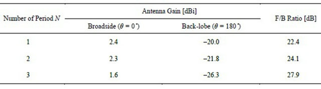
The optimized physical dimensions (in millimeters) of the MSA and the stand-up SRR are as follows: S = 120, G = 75, P = 18, d = 15.1, a = 13.8, w = 0.4, h = 1.27 and g = 0.7. In total, six SRRs are placed 0.5 mm off the ground plane along the H-plane edge direction (x-axis) of the MSA. Initially, the effect of varying the number of periods N in terms of the F/B ratio of the MSA was studied. Figure 8 shows the geometry of the soft surface made with two periods of SRRs (N = 2) near ground plane. It can be seen from Table 2 that the back-lobe gain of the MSA is reduced as the number of period increases. However, the broadside gain of the MSA decreases significantly when the number of periods is three (N = 3). This is attributed to the fact that a portion of the diffracted waves radiated from the ground plane edges also contributes to space waves. As a result, two period of array structure with four SRRs was used in this design.
The distance l between the ground plane edge and the arrayed SRRs is another determinant parameter. The effect of introducing the soft surface made with two periods of SRRs (N = 2) near ground plane was studied as a function of the distance l from the ground plane edge to the SRRs. Figure 9 shows the simulated broadside and back-lobe gain of the MSA for the different values of distance l. An important fact related to F/B ratio of the MSA is that the decrease of the distance l does not necessary guarantee a reduction in the back radiation, as it
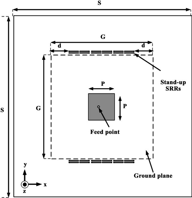
Figure 7. Geometry of a MSA loaded with the soft surface in partially removed ground plane.
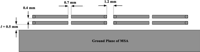
Figure 8. Geometry of the soft surface made with two periods of stand-up SRRs (N = 2) near the ground plane edge.
Table 2. Comparison of simulated gain and F/B ratio for the different number of period N.
could be expected. From Figure 9, the maximum F/B ratio of 24.1 dB is obtained for the following case: l = 0.5 mm. Figure 10 shows a comparison of the simulated input reflection coefficient (S11) of the MSA with/without stand-up SRRs. The resonant frequency of the MSA decreases from 2.5 to 2.445 GHz owing to the loading effect of the array of stand-up SRRs.
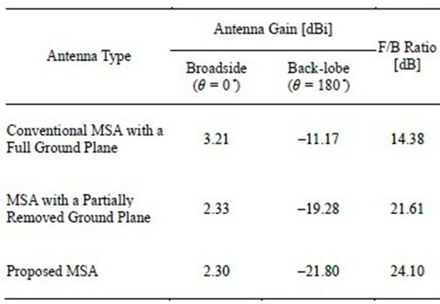
For the sake of comparison, the simulated Eand Hplane radiation patterns of the different MSAs at 2.445 GHz are shown in Figure 11. It is observed that the back radiation is reduced when both partial ground-plane removal and a soft-surface structure consisting of the arrayed stand-up SRRs are used. The simulated gains at different angles (θ = 0˚, 180˚) and the F/B ratios of the MSAs are summarized in Table 3. Notably, the back radiation level of the proposed MSA shows improvements in both the E-plane (xz-plane) and the H-plane (yz-plane). The partially removed ground plane structure of the proposed MSA can suppress the surface wave propagation along the E-plane edge direction (y-axis) and the soft surface structure with stand-up SRRs reduces the groundplane edge diffraction along the H-plane edge direction (x-axis) simultaneously. As a result the back radiation level of the proposed MSA can be reduced further. It is noted that a slight reduction in the broadside gain of the MSA is caused by the fact that a portion of the diffracted waves radiated from the ground plane edges contributes to both the forward waves and the backward waves. In comparison with the conventional MSA having a full ground plane of the same size, the broadside gain (at θ = 0˚) of the proposed MSA reduced by 0.9 dBi. However, the back-lobe gain (at θ = 180˚) was improved by around 10.7 dBi. As a result, the F/B ratio increased from 14.38 to 24.1 dB owing to partial ground-plane removal and the use of the soft-surface structure.
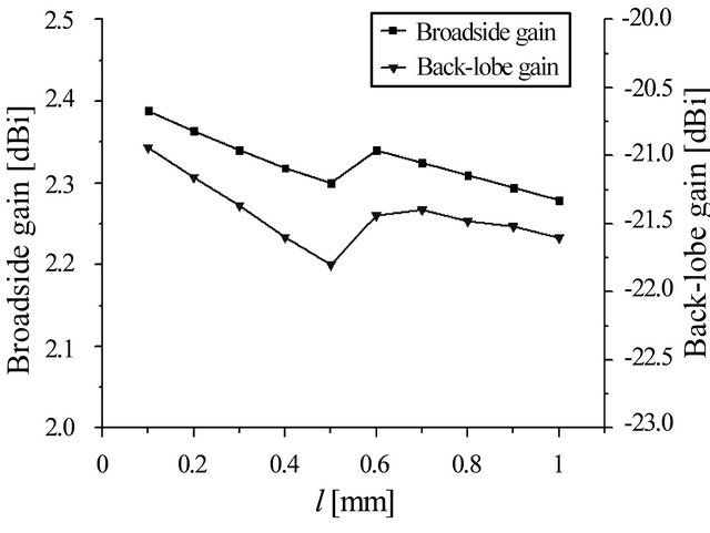
Figure 9. Simulated broadside and back-lobe gain of the MSA as a function of the distance l between the ground plane edge and the arrayed SRRs (N = 2).
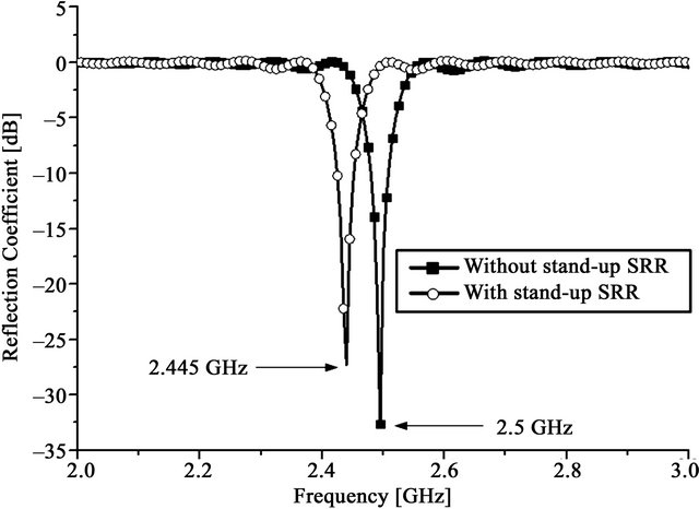
Figure 10. Simulated input reflection coefficient (S11) of a MSA with/without stand-up SRRs.
 (a)
(a)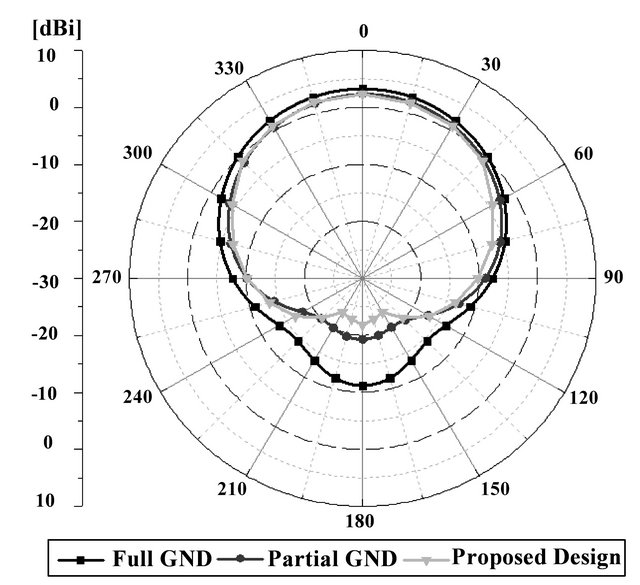 (b)
(b)
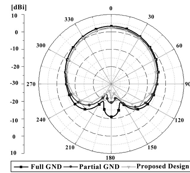
Figure 11. Simulated radiation patterns of the different MSAs. (a) E-plane. (b) H-plane.
3. Experimental Results
In order to verify the simulations, a prototype MSA loaded with the soft surface in a partially removed ground plane is fabricated on a Rogers R3210 substrate (having a relative dielectric constant of 10.2, a thickness of 1.27 mm, and a loss tangent of 0.0025); a 50 Ω SMA coaxial probe connecter is installed for feeding the MSA. The photograph of the fabricated antenna is shown in Figure 12. The total size of the MSA is 120 mm × 120 mm. Figure 13 shows a comparison of the simulated and measured reflection coefficient of the proposed MSA. It can be noted that a slight reduction in the measured bandwidth (S11 < –10 dB) in comparison with that of the simulated result is attributed to the fabrication tolerances. However, the measured and simulated resonant frequencies of the MSA agree well with each other. The simulated and measured radiation patterns at a frequency of 2.445 GHz are shown in Figure 14.
In both the E-and the H-planes, the MSA shows a smooth symmetric omni-directional pattern with slight backward radiation. The measured broadside (at θ = 0˚) and back-lobe gains (at θ = 180˚) are around 2.8 and –21.4 dBi, respectively. As a result, an F/B ratio of 24.2 dB was achieved experimentally.
Table 3. Comparison of simulated gain and F/B ratio.
 (a)
(a)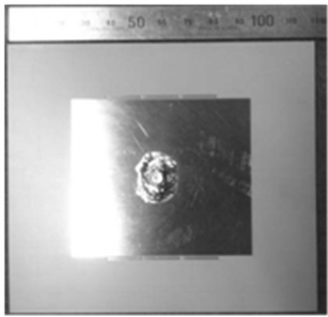 (b)
(b)
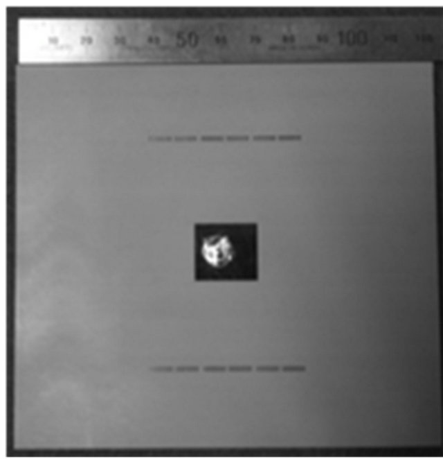
Figure 12. Photographs of the fabricated antenna: (a) Topview; (b) Bottom-view.
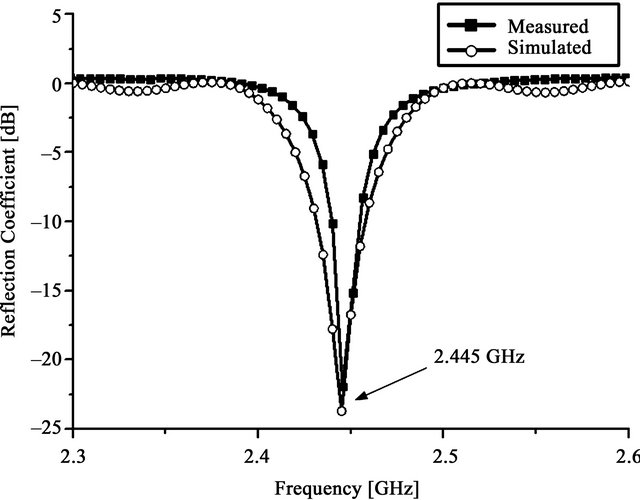
Figure 13. Simulated and measured reflection coefficient of the proposed MSA.
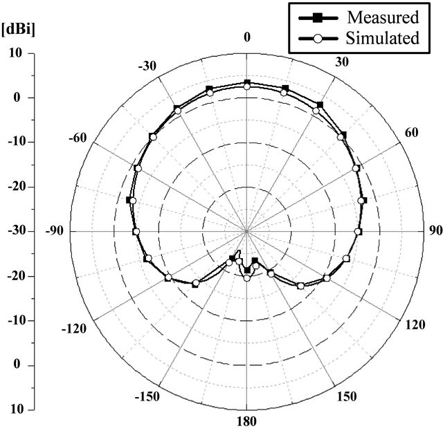
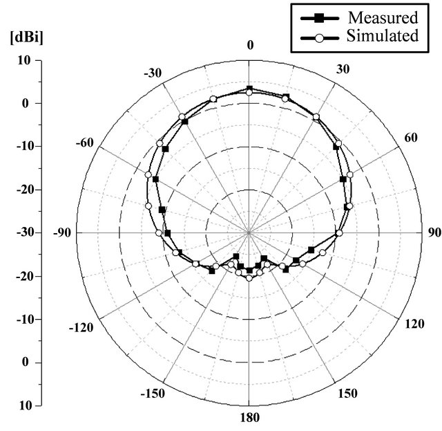
Figure 14. Simulated and measured radiation patterns of the different MSAs at 2.445 GHz.
4. Conclusion
We have investigated the effects of partial metallic ground plane removal on the radiation characteristics of a MSA. The partial ground plane removal method has been shown to improve the F/B ratio of the MSA by at least 9.7 dB as compared with that of a conventional MSA having a full ground plane of the same size. The structure of the proposed MSA is very simple and can be implemented with ease. When this structure is used between two MSAs, a mutual coupling reduction effect can also be generated. This structure can be applied for reducing back radiation in the MSA antenna design.
REFERENCES
- N. Llombart, A. Neto, G. Gerini and P. de Maagt, “Planar Circularly Symmetric EBG Structures for Reducing Surface Waves in Printed Antennas,” IEEE Transactions on Antennas Propagation, Vol. 53, No. 10, 2005, pp. 3210- 3218. doi:10.1109/TAP.2005.856365
- H. Boutayeb and T. A. Denidni, “Gain Enhancement of a Microstrip Patch Antenna Using a Cylindrical Electro Magnetic Crystal Substrate,” IEEE Transactions on Antennas Propagation, Vol. 55, No. 11, 2007, pp. 3140- 3145. doi:10.1109/TAP.2007.908818
- T. T. Thai, G. R. Dejean and M. M. Tentzeris, “Design and Development of a Novel Compact Soft-Surface Structure for the Front-to-Back Ratio Improvement and Size Reduction of a Microstrip Yagi Array Antenna,” IEEE Antennas and Wireless Propagation Letters, Vol. 7, 2008, pp. 369-373. doi:10.1109/LAWP.2008.2001818
- E. Rajo-Iglesias, Q. Quevedo-Teruel and L. Inclan-Sanchez, “Planar Soft Surfaces and Their Application to Mutual Coupling Reduction,” IEEE Transactions on Antennas Propagation, Vol. 57, No. 12, 2009, pp. 3852-3859.
- E. Rajo-Iglesias, L. Inclan-Sanchez and O. Quevedo-Teruel, “Back Radiation Reduction in Patch Antennas using Planar Soft Surfaces,” Progress in Electromagnetics Research Letters, Vol. 6, 2009, pp. 123-130. doi:10.2528/PIERL08111202
- J. Papapolymerou, R. F. Drayton and L. P. B. Katehi, “Micromachined Patch Antennas,” IEEE Transactions on Antennas Propagation, Vol. 46, No. 2, 1988, pp. 275-283. doi:10.1109/8.660973
- O. Quevedo-Teruel, L. Inclan-Sanchez and E. Rajo-Iglesias, “Soft Surfaces for Reducing Mutual Coupling between Loaded PIFA Antennas,” Progress in Electromagnetics Research Letters, Vol. 9, 2010, pp. 91-94. doi:10.1109/LAWP.2010.2043632
- I. Gallego-Gallego, O. Quevedo-Teruel, L. Inclan-Sanchez, E. Rajo-Iglesias and F. J. García-Vidal, “On the Use of Soft Surfaces to Reduce Back Radiation in Textile Microstrip Patch Antennas,” Proceedings of the 5th Eu-CAP, 2011, pp. 534-537.
- S. B. Yeap and Z. N. Chen, “Microstrip Patch Antennas with Enhanced Gain by Partial Substrate Removal,” IEEE Transactions on Antennas Propagation, Vol. 58, No. 9, 2010, pp. 2811-2816. doi:10.1109/TAP.2010.2052572
- J. Huang, “The Finite Ground Plane Effect on the Microstrip Antenna Radiation Patterns,” IEEE Transactions on Antennas Propagation, Vol. 31, No. 4, 1983, pp. 649-653. doi:10.1109/TAP.1983.1143108