Wireless Engineering and Technology
Vol.1 No.2(2010), Article ID:3026,10 pages DOI:10.4236/wet.2010.12009
Resonant Length Formulations for Dual Band Slot Cut Equilateral Triangular Microstrip Antennas
![]()
1DJSCOE, Vile – Parle (W), Mumbai, India; 2SAMEER, Mumbai, India.
Email: amitdeshmukh76@yahoo.com, kpray@rediffmail.com
Received August 2nd, 2010; revised September 22nd, 2010; accepted September 28th, 2010.
Keywords: Equilateral Triangular Microstrip Antenna, Dual Band Microstrip Antenna, U-Slot, Pair of Rectangular Slots
ABSTRACT
The dual band equilateral triangular microstrip antennas are realized by cutting the slots of either quarter wave or half wave in length, inside the patch. In this design, however these simpler approximations of slot length against the frequency do not give closer results for different slot lengths and there positions inside the patch. In this paper, the modal variations of slot cut patch antennas over wide frequency range are studied. It is observed that the slot does not introduce any mode but reduces the higher order mode resonance frequency of the patch and along with the fundamental mode realizes dual band response. The formulations of the resonant length for the mode introduce by the slots in these antennas are proposed. The resonance frequencies calculated using proposed formulations agree well with the simulated results with an error of less than 5%.
1. Introduction
The dual band microstrip antenna (MSA) is realized by cutting a slot at an appropriate position inside the patch [1-3]. Since the slots are cut inside the patch, they neither increase the patch size nor largely affect the radiation pattern of the patch. These slots can take different shapes like, rectangular or square slot, step slot, tooth-brush shaped slot, V-slot, U-slot, etc [4-8]. The slot adds another resonant mode near the fundamental mode of the patch and realizes dual frequency response. The dual band equilateral triangular MSA (ETMSA) have also been realized by cutting the pair of rectangular or U-slot inside the patch [4-9]. While designing these slotted MSAs for the required frequency, depending upon where they are cut in the patch, the slot length is taken equal to nearly half wave or quarter wave in length. Towards the shorted end of the slot, the surface currents encircles over a finite length, which stores magnetic energy towards the shorted slot end [10]. To account for this an additional length is added to this half or quarter wavelength. This additional length is reported to be 10% of the slot length at the required frequency [10]. However it was observed that these simpler approximations of slot length against the frequency do not give closer results for varying slot lengths and their positions inside the patch. Therefore an in-depth analysis for the slot cut MSA is required over a wide frequency range so as to accurately model the slot length at the required frequency.
In this paper, the slot frequencies for U-slot or rectangular slots cut dual band ETMSAs, calculated by using their half wave or quarter wave length approximations are compared with the simulated values obtained using IE3D software [11]. It was observed that the above approximations give larger error for wide range of slot lengths and their positions inside the patch. Therefore a detail modal analysis for these slots cut ETMSAs was carried out over a wide frequency range using the surface current distributions obtained using IE3D software. It was observed that the U and rectangular slots alters the resonance frequency of higher order TM11 mode of ETMSA and along with its fundamental TM10 mode realizes dual band response. The radiation pattern at the TM10 mode for ETMSA is in the broadside direction whereas at TM11 mode it is in the conical direction. Since the slot affects the current distribution on the patch at TM11 mode, with the increasing slot length the radiation pattern at the modified TM11 frequency becomes in the broadside direction. The cross-polarization levels decreases with the increase in slot length. The surface current distributions for slot cut ETMSAs were studied for different slot lengths and the resonant length formulation for the slot (modified higher order) mode and patch mode is proposed. The resonant frequencies calculated using the proposed formulations agrees well with the simulated results with an error of less than 5% over the entire slot length range. The formulations are first proposed on glass epoxy substrate (er = 4.3, h = 0.16 cm, and tan d = 0.02) and further they are validated on RT-Duroid substrate (er = 2.33, h = 0.16 cm, and tan d = 0.001).
2. Dual Band Slot Cut ETMSAs
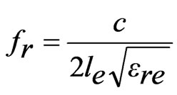
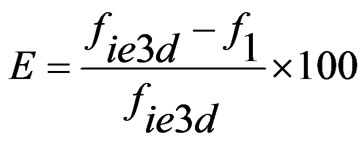
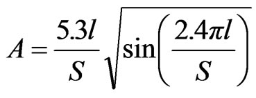
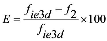
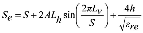
In most of the reported slotted antennas the slot length is taken to be equal to half or quarter wave in length. In dual band pair of rectangular slots cut ETMSA as shown lengths (l) from 0.5 to 4.0 cm, the equivalent slot resonant length is calculated by adding the correction length as given in Equation (1). The slot frequency is calculated by using Equation (2). Since the surface currents circulate around the slot, the effective dielectric constant (ere) is calculated by using the average of the widths on the two sides of the slot [1]. For different values of Y, the frequencies calculated using Equations (1) and (2) are plotted against the simulated frequencies obtained using IE3D in Figure 1(b-d). The % error (E) with respect to the simulated value is calculated by using Equation (3) and it is also plotted in the same figure.
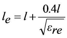 (1)
(1)
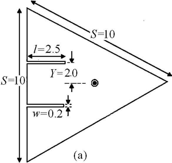
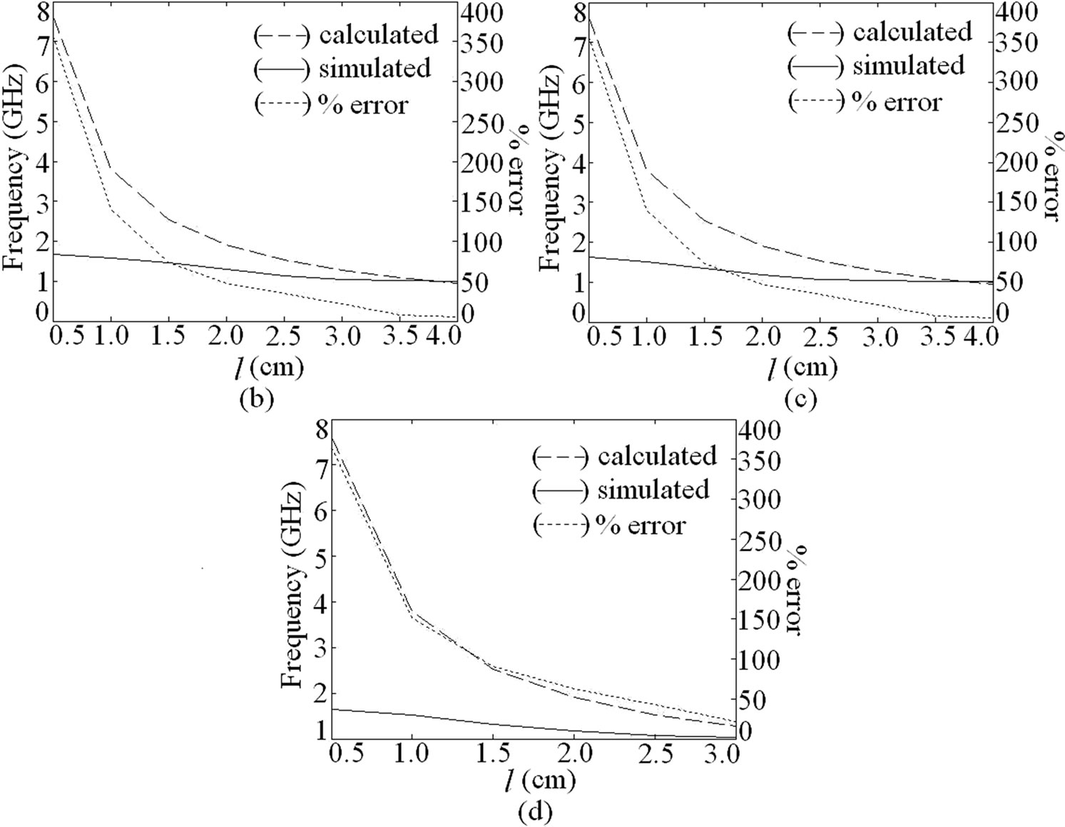
Figure 1. (a) ETMSA with pair of slots and its resonance frequency and % error plots for (b) Y = 1; (c) Y = 2 and (d) Y = 3.
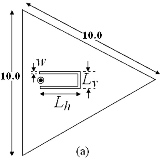
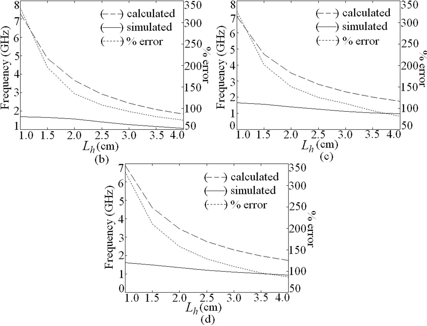
Figure 2. (a) U-slot cut ETMSA and its resonance frequency and % error plots for (b) Lv = 1; (c) Lv = 2 and (d) Lv = 3.
 (2)
(2)
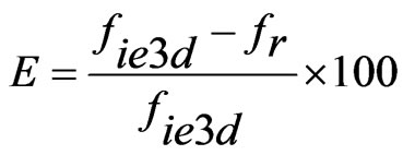 (3)
(3)
Using this approach for some values of Y and only for larger l, a smaller E is obtained. The dual band U-slot cut ETMSA is shown in Figure 2(a). The inner U-slot length equals half the wave length. The ere is calculated by using the inner U-slot width (Lv – 2w). The resonant length and frequency is calculated by using Equations (4) to (6). For different values of Lv and Lh, the slot frequency calculated by using the following equations and that obtained using IE3D are shown in Figures 2(b-d). For all the values of U-slot dimension, a larger E as calculated by using Equation (3), is observed.
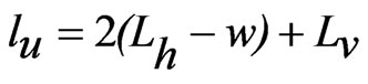 (4)
(4)
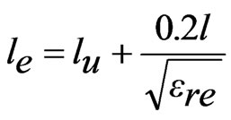 (5)
(5)
 (6)
(6)
Thus the quarter wave or half wave length approximations of the slot length against the frequency do not give closer results. Hence in-depth analysis of slot cut MSAs is required to understand the slot mode. The ETMSA in above configurations, on glass epoxy substrate has, TM10 and TM11 mode resonance frequencies of 958 and 1690 MHz as shown in its resonance curve plot in Figure 3(a). The surface current distributions at these two modes are shown in Figures 3(b, c). At TM10 mode the currents show half wavelength variation along side length (S) whereas at TM11 mode the currents show half wave length variations along S as well as along base of the ETMSA [1]. In the dual band ETMSA as shown in Figure 1(a), the slot length l is increased in steps of 0.5 cm from 0.5 to 4.0 cm and the surface current distributions for each value of l and for different slot position (Y) were studied. For slot dimensions of l = 2.5 cm, w = 0.2 cm and Y = 2.0 cm, the dual frequencies are f1 = 940 MHz and f2 = 1176 MHz, as shown in the resonance curve plot in Figure 3(a). The current distributions at these two frequencies are shown in Figures 3(d, e). As seen from the current distributions for ETMSA and ETMSA with pair of slots and the resonance curve plot that the pair of rectangular slots perturbs the surface currents and reduces the TM11 mode resonance frequency from 1690 to 1176 MHz as shown in Figure 3(a). Here the slots do not introduce any mode but reduces the higher order mode resonance frequency and f2 is governed by this modified (due to the slots) TM11 resonance frequency. The f1 is governed by TM10 mode of ETMSA, as half wavelength variation in surface currents is present along S. This frequency is also marginally affected by slots as shown in Figure 3(a). The radiation pattern for ETMSA at TM11 mode and for slot cut ETMSA for two different slot lengths are shown in Figures 4(a-c). At TM11 mode, the pattern is in the conical direction. However since the slots affects the current distributions on the patch, with the increasing slot length the radiation pattern becomes in the broadside direction. Also as observed from the patterns, the cross polarization levels decreases with the slot length.
Similar study is carried out for U-slot cut ETMSA. The resonance curve plot for ETMSA and for U-slot cut ETMSA (U-slot dimension: Lh = 3.0, Lv = 1.0, w = 0.2 cm) are shown in Figure 5(a). The surface current distributions at the dual frequencies for U-slot cut ETMSA is shown in Figures 5(b, c). As seen from the current distributions and resonance curve plots, the horizontal slot of the U-slot reduces the TM11 mode resonance frequency and f2 is governed by this modified TM11 mode. This frequency has reduced from 1690 to 1324 MHz. The f1 is governed by TM10 mode. This frequency is also reduced since the vertical U-slot length is orthogonal to surface currents at TM10 mode and it increases the surface currents length. The radiation patterns at f2 for two different U-slot lengths are shown in Figures 5(d, e). Similar to the above dual band ETMSA, the U-slot affects the current distributions on patch at f2 and gives broadside radiation pattern. The cross polar level decreases with increasing U-slot length. In the following section by studying current distributions at dual frequencies the formulation of resonant length at dual frequencies for the above slot cut ETMSAs are proposed.
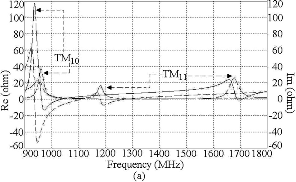
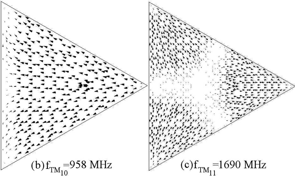
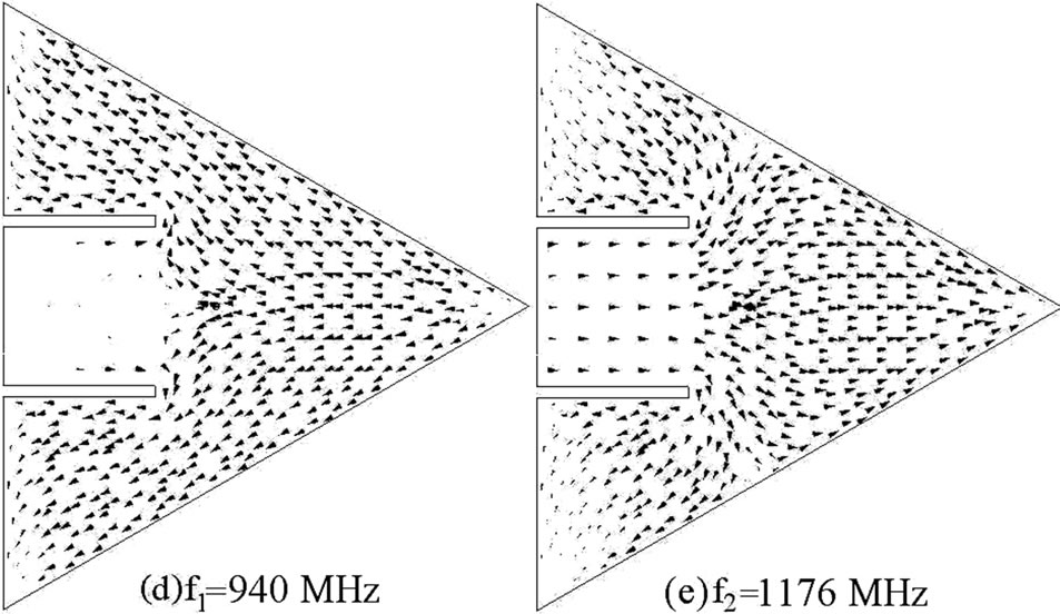
Figure 3. (a) Resonance curve plot for ETMSA (__ __ __) Re, (____) Im, and ETMSA with pair of slots (____ _ ____) Re, (_ _ _ _) Im, its (b, c) surface current distributions at TM10 and TM11 modes and surface current distributions for dual slot cut ETMSA at (d) f1 and (e) f2。
3. Formulation of Resonant Length for Slot Cut ETMSA
The modal variations for ETMSA in voltage and currents are with respect to the centroid of the patch [1]. For S = 10 cm, the centroid point lies at nearly 3 cm from the base of ETMSA. For TM10 mode the current maxima is present at the centroid point whereas at TM11 mode the voltage maximum is present at the centroid point [1]. Due to these different variations in current and voltage distributions at two modes, for pair of rectangular slots
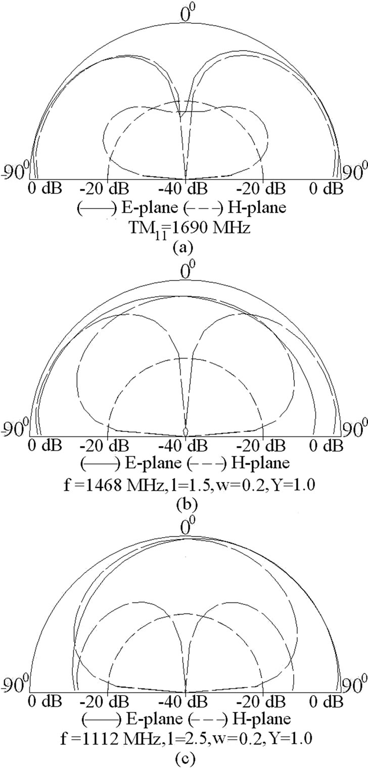
Figure 4. Radiation pattern for ETMSA at (a) TM11 mode and at f2 for (b,c) different lengths of pair of slots.
cut ETMSA as shown in Figure 1(a), for l > 3 cm, the decrease in f2 is smaller whereas decrease in f1 is larger.
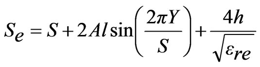
The resonance frequency of ETMSA depends upon the effective side length (Se) [1]. To formulate f1 (modified TM10 mode) for pair of slots cut ETMSA, Se is modified with respect to the l and the resonance frequency is calculated by using Equations (7) to (12).
 (7)
(7)
 (8)
(8)
 (9)
(9)
 (10)
(10)
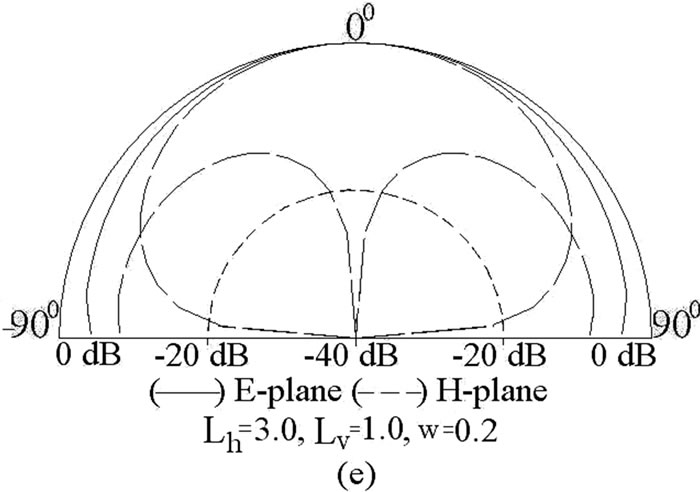
Figure 5. (a) Resonance curve plot for ETMSA (____) Re, (__ __ __) Im, and ETMSA with U-slot (_ _ _ _) Re, (____ _ ____) Im, surface current distributions at (d) f1 and (e) f2 for U-slot cut ETMSA and its (d,e) radiation pattern for different U-slot lengths.
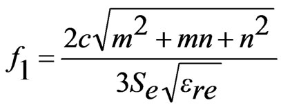
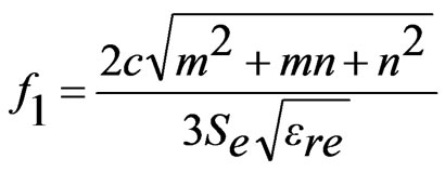 , m = 1, n = 0 for TM10 (patch mode) (11)
 (12)
(12)
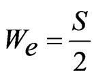
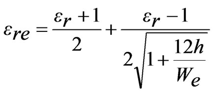
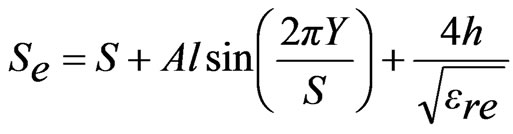
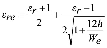
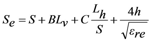
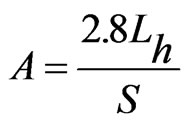
The width as seen by the surface currents varies from base of ETMSA towards the vertex point. Towards the base, it is equal to S and towards the opposite vertex point it is nearly equal zero. Hence the effective width (We) is taken equal to be the average of the width along ETMSA length as given in Equation (7). The ere is calculated by using Equation (8). For smaller l, decrease in f1 is smaller and for larger l, decrease in f1 is larger. To account for this non-linear variation, a weighting function (A) in terms of l is used as given in Equation (10). The equation for A is derived based on the variation in frequency of TM10 mode against l. For a given l, with increase in Y, the perturbation in surface current length increases (or the frequency reduces) since the slots are placed towards the maximum current location. This variation is accounted by using the sinusoidal term, as given in Equation (9). The fringing field extension is accounted by the last term in the right hand side of Equation (9). The frequency is calculated by using Equation (11) and the % error (E) between the calculated and simulated values with respect to the simulated value, is calculated by using Equation (12) and they are plotted in Figures 6(a-f). For the entire slot length range, an E of less than 5% is obtained. The resonant length at f2 is formulated by modifying Se with respect to l as given in Equations (13) to (16).
 (13)
(13)
 (14)
(14)
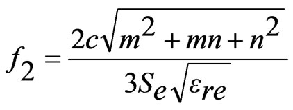
 , m = 1, n = 1 for TM11 (slot mode) (15)
 (16)
(16)
The factor ‘2’ in Equation (13) is to account for the circulation of surface currents around the slot length. The perturbation in surface current length is modeled by using the weighting function A and the equation for the same is derived based on the frequency variation with respect to l at TM11 mode. The variation in the frequency with Y, for given l, is modeled by using sinusoidal function in Equation (13). The Y is varied from 1 to 3 cm and the l is varied from 0.5 to 4.0 cm. The frequency f2 obtained
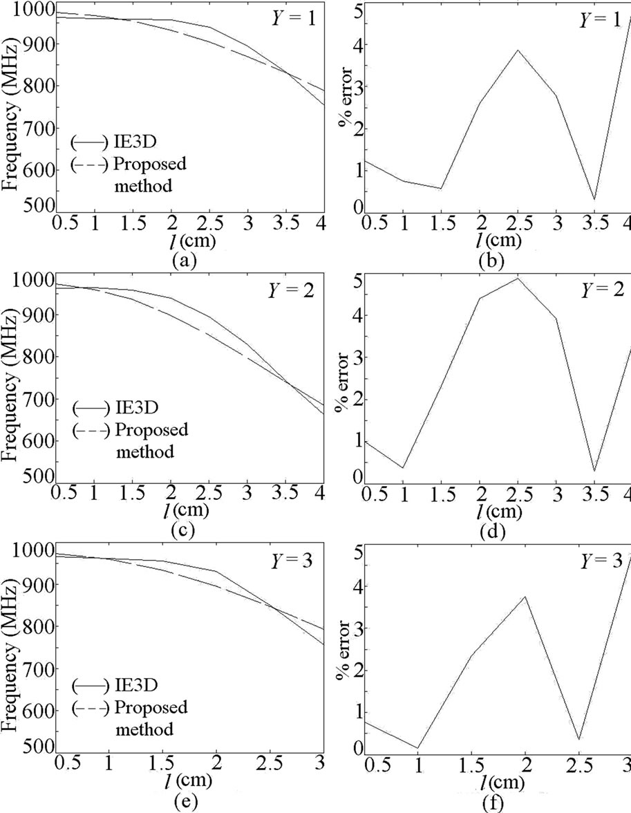
Figure 6. (a-f) Resonance frequency and % error plots for dual band pair of slots cut ETMSA at f1.
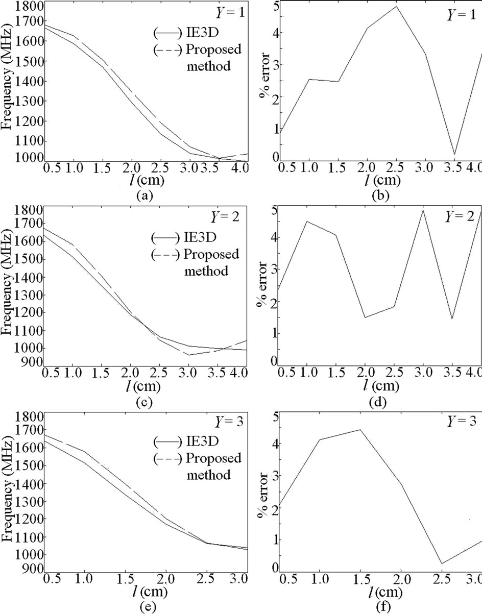
Figure 7. (a-f) Resonance frequency and % error plots for dual band pair of slots cut ETMSA at f2.
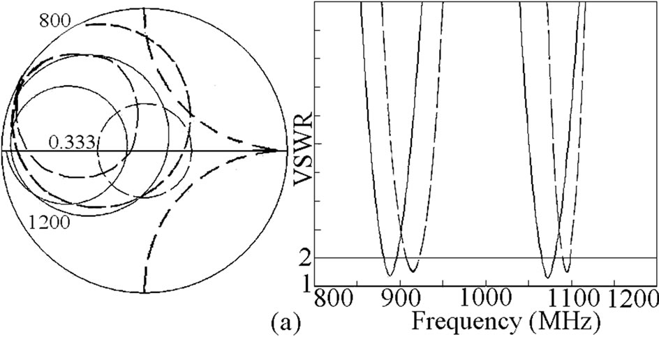
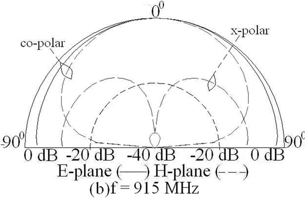
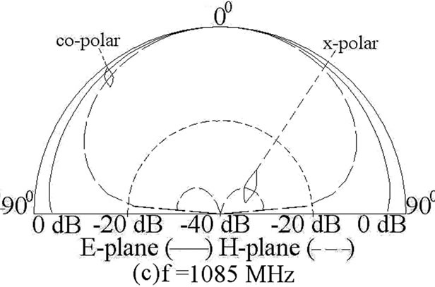
Figure 8. (a) Input impedance and VSWR plots, (____) simulated, (_ _ _) measured, and (b, c) measured radiation pattern for ETMSA with pair of slots.
using simulation, calculated by using Equation (15), and E calculated by using Equation (16) are plotted in Figures 7(a-f). For all the values of Y, a close match is obtained between the simulated and calculated frequencies.
While designing the pair of rectangular slots cut ETMSA for the given two frequencies, the separation between the pair of slots is selected first as it affects the impedance matching at the two frequencies. Due to the ETMSA patch geometry, Y is taken to be less than S/4, so as to have larger variation in l and hence the frequency. Thus Y = 2 is selected. For the desired dual frequencies of 860 and 1060 MHz, the slot length obtained from Figures 6 and 7 is = 2.5 cm. The slot width of 0.2 cm is selected. The slotted ETMSA is simulated and dual frequencies and BW’s are 888, 1073 MHz and 15, 15 MHz, respectively as shown in Figure 8(a). This response is experimentally verified and the measured frequencies and BW’s are 910, 1089 MHz and 12, 13 MHz, respectively as shown in Figure 8(a). The frequency values obtained using proposed equations are very close to the simulated and measured frequencies. The radiation pattern at dual frequencies is shown in Figures 8(b, c). The E and H-planes at both the frequencies are aligned along F = 00 and 900, respectively. The pattern is in the broadside direction at both the frequencies with the cross polar levels less than 12 dB as compared to the co-polar levels. Although the radiation pattern at TM11 mode of ETMSA is conical, but since the pair of slots affects the current distributions on the patch at f2, the radiation pattern is in the broadside direction.
As seen from the current distributions for U-slot cut ETMSA, the U-slot affects the surface current distributions at TM10 as well as TM11 mode and realizes dual band response. At f1, the TM10 mode is dominant as half wave length variation in surface currents is present along S. However due to the finite Lv, the surface current length is perturbed and the frequency is reduced. At f2, the horizontal slots of the U-slot modify the TM11 mode resonance frequency and this frequency is governed by modified TM11 mode. The formulation of resonant length at f1 is given by modifying Se with respect to the U-slot dimensions as given in Equations (17) to (20).
For f1,
 (17)
(17)
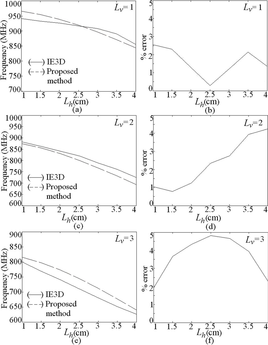
Figure 9. (a-f) Resonance frequency and % error plots for dual band U-slot cut ETMSA at f1.
 (18)
(18)
 (19)
(19)
 , m = 1, n = 0 for TM10 mode (20)
For narrow slots, (Lv < S/4), the perturbation in surface current length is lesser. In those cases, using B = 0 and A = 1, a closer prediction in resonant length is obtained. For Lv > S/4, the perturbation in surface current length increases and hence by using B = 0.6 and A = 2, a closer prediction in the length and the resonance frequency is obtained. The f1 calculated by using Equation (20) and E calculated by using Equation (12) are plotted in Figures 9(a-f). Using the proposed formulations, for all the slot dimensions, an E of less than 5% is obtained. At f2, the formulation in resonant length is obtained by using Equations (21) to (23).
For f2,
 (21)
(21)
 (22)
(22)
 , m = 1, n = 1 for TM11 mode (23)
Similar to pair of slots cut ETMSA, the factor ‘2’ in Equation (21) is to account for the circulation of surface currents around the slot length. To account for the current variation in TM11 mode a sinusoidal function in Lv is used in Equation (21). The A is the weighting function and the relation for A is derived based on variation in frequency with respect to U-slot dimensions for TM11 mode. The frequency and E are calculated by using Equations (23) and (16), respectively and they are plotted in Figures 10(a-f). For the entire range, frequencies calculated using the proposed formulations agrees closely with the simulated values. For designing the U-slot cut ETMSA, first the value of Lv is selected. For the dual frequencies of 900 and 1300 MHz, using Lv = 1.0 cm and w = 0.2 cm, the horizontal U-slot length obtained by using frequency plots in Figures 9 and 10 is, Lh = 3.0. This ETMSA with U-slot is simulated using IE3D and the
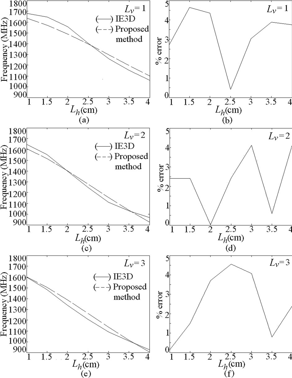
Figure 10. (a-f) Resonance frequency and % error plots for dual band U-slot cut ETMSA at f2.
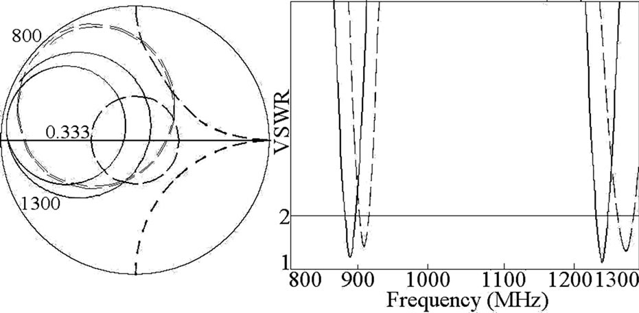
Figure 11. Input impedance and VSWR plots for ETMSA with U-slot, (____) simulated, (_ _ _) measured.
frequencies and BW’s are 883, 1245 MHz and 15, 18 MHz, respectively as shown in Figure 11. The U-slot cut ETMSA is fabricated and the measured frequencies and BW’s are 910, 1275 MHz and 15, 19 MHz, respectively as shown in Figure 11. The frequencies calculated using proposed equations agrees well with the simulated and measured results. The radiation pattern at the two frequencies is in the broadside direction. The E and H-planes are aligned at F = 00 and 900, respectively. At f2, a higher cross polarization is present. The cross polar level decreases with the increase in U-slot dimensions. These proposed formulations are also validated on RTduroid substrate. Using duroid substrate, for to have
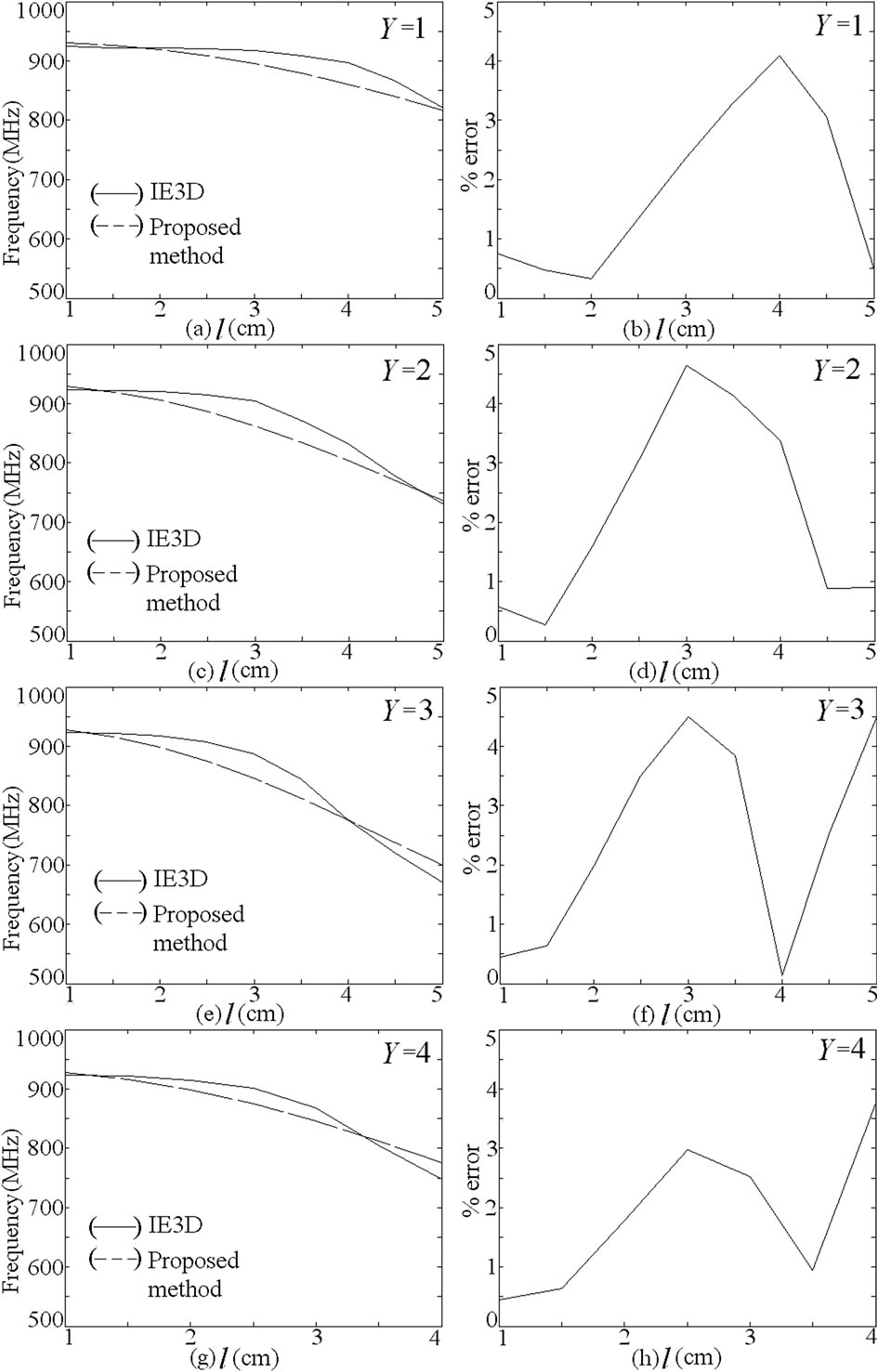
Figure 12. (a-h) Resonance frequency and % error plots for pair of slots cut ETMSA using RT-duroid substrate at f1.
TM10 resonance frequency nearly equal to 950 MHz, the S equals 14 cm. For pair of rectangular slots cut ETMSA, the f1 and f2 obtained using IE3D and the proposed formulations and E between them are shown in Figures 12 and 13. For duroid substrate also a closer agreement between the two results is realized. Similar results are obtained for U-slot cut ETMSA.
4. Conclusions
The resonance frequency calculation for slot mode in pairs of rectangular slots and U-slot cut ETMSAs using quarter and half wavelength approximations are discussed. It was observed that they give closer match only for some values of slot lengths and their positions inside the patch. An in-depth modal analysis for pair of rectangular slots cut and U-slot cut ETMSA was carried out and it is observed that the slots does not introduce any mode but reduces the higher order TM11 resonance frequency of ETMSA and along with the fundamental TM10 mode realizes dual frequency response. The slots affects the current distribution on the patch at TM11 mode and thus with increasing slot length the radiation pattern at the frequency due to the slot becomes in the broadside direction. The cross polarization level reduces with the slot length. By studying the surface current distributions at the dual frequencies, the formulation in resonant length at dual frequencies is proposed for these slotted ETMSAs and the frequencies obtained using these formulations agree closely with the simulated as well as measured results.
REFERENCES
- G. Kumar and K. P. Ray, “Broadband Microstrip Antenna,” Artech House, Norwood, 2003.
- R. Garg, P. Bhartia, I. Bahl and A. Ittipiboon, “Microstrip Antenna Design Handbook,” Artech House, Norwood, 2001.
- K. P. Ray and D. D. Krishna, “Compact Dual Band Suspended Semicircular Microstrip Antenna with Half U-Slot,” Microwave & Optical Technology Letters, Vol. 48, No. 10, 2006, pp. 2021-2024.
- K. L. Wong, “Compact and Broadband Microstrip Antennas,” John Wiley & sons, Inc., New York, 2002.
- A. E. Daniel and R. K. Shevgaonkar, “Slot-Loaded Rectangular Microstrip Antenna for Tunable Dual-Band Operation,” Microwave & Optical Technology Letters, Vol. 44, No. 5, March 2005, pp. 441-444.
- J. H. Lu, “Single Feed Dual Frequency Rectangular Microstrip Antenna with Pair Step Slots,” Electronics Letters, Vol. 35, No. 5, 1999, pp. 354-355.
- J. Y. Sze and K. L. Wong, “Broadband RMSA Using Tooth-Brush Shaped Slots,” Electronics Letters, Vol. 34, No. 23, November 1998, pp. 2186-2187.
- A. A. Deshmukh and G. Kumar, “Even Mode Multi-Port Network Model for Slotted Dual Band Rectangular Microstrip Antennas,” Microwave & Optical Technology Letters, Vol. 48, No. 4, 2006, pp. 798-804.
- A. A. Deshmukh and K. P. Ray, “Multi-Band Equilateral Triangular Microstrip Antennas,” Proceedings of Recent Advances in Microwave Theory and Applications, Jaipur, 21-24 November 2008.
- J. B. Knorr and J. Saenz, “End Effect in a Shorted Slot,” IEEE Transactions on Microwave Theory & Techniques, September 1973, pp. 579-580.
- IE3D 12.1, Zeland Software, Freemont, 2004.