Smart Grid and Renewable Energy
Vol.05 No.12(2014), Article ID:52883,11 pages
10.4236/sgre.2014.512027
Control System Development and Test for the Operation of a Micro-Grid System―PART II
Razzaqul Ahshan, Mohammad Tariq Iqbal, George K. I. Mann, John E. Quaicoe
Faculty of Engineering and Applied Science, Memorial University of Newfoundland, St. John’s, Canada
Email: razzaqul.ahshan@cna.nl.ca
Copyright © 2014 by authors and Scientific Research Publishing Inc.
This work is licensed under the Creative Commons Attribution International License (CC BY).
http://creativecommons.org/licenses/by/4.0/


Received 23 September 2014; revised 20 October 2014; accepted 25 November 2014
ABSTRACT
This paper presents experimental development and performance testing of an active power controller for stable and reliable operation of a micro-grid system. In order to achieve accurate and fast power balance in a micro-grid system that contains renewable energy sources, power in the system has to be regulated continuously. Such an objective can be achieved using droop based alternating current control technique. Because the droop characteristic employed into the develo- ped controller initiates to determine the power deviation in the system which is continuously regulated by controlling the current flow into dump power resistors. The designed controller is tested and validated using a micro-grid prototype in the laboratory environment for stand-alone mode of operation under various operating conditions. The key development in the micro-grid prototype is the development of a wind turbine simulator. A dSPACE ds1104 DSP board is used to implement and interface the designed controller with the micro-grid system. The experimental investigation of the developed controller presents the significant capability to achieve continuous power balance in the micro-grid system, while it maintains stable and reliable operation of the system. Finally, the power quality of the isolated micro-grid system is presented and discussed under the operation of the developed controller.
Keywords:
Active Power Controller, Micro-Grid Prototype, Renewable Energy Sources, Wind Turbine Simulator

1. Introduction
Increasing energy demand, environmental concern, de-regulated market policy and technology advancement are main causes to integrate distributed generation (DG) units into power system network. Such integration process leads the conventional power system to the new power system domain called micro-grid system. A micro-grid system generally composed of DG units with diverse generating capacity, availability, primary energy and operational costs. The application of such DG units in a micro-grid domain requires delivering stable, reliable and sustainable power generation, conversion, storage as well as distribution and exchanging during the entire operational time of the micro-grid system. In order to achieve such operational objectives, coordination and control in a micro-grid system is essential with the consideration of a series of factors such as availability of power generation, operational modes, voltage and frequency limitation, micro-grid load demands, renewable power penetration as well as energy cost [1] [2] .
Operation and control of an isolated micro-grid system consisting of renewable power generations becomes critical because of the stochastic variation in primary energy sources such as wind speed, solar isolation etc. Such variation always leads to the change in active power generated by the DG units in the micro-grid system. As a result the active power generation in the micro-grid system varies randomly that results an active power mismatches between generation and consumption, which is stochastically varying in nature. Moreover, low inertia in the isolated micro-grid system as compared to a conventional power system along with stochastic behavior in active power mismatches can easily lead the micro-grid system instability. Hence, continuous and smooth active power regulation in an isolated micro-grid system has become an important issue to achieve stable and reliable operation of the system that comprises of renewable power generations such as wind turbines, photovoltaic panel etc.
Power management strategies in a micro-grid system proposed by R. H. Lasseter is carried out by controlling the power angle between the voltages at the voltage source converter and the micro-grid voltage for each micro-source [3] , where micro-sources are assumed to be converter interfaced in the micro-grid domain. The successful laboratory test of a micro-grid system presented in [3] is performed and reported in [4] . The application of non-inverter interfaced DG units and storage systems in such micro-grid systems is also studied [4] . Power sharing technique among multiple DGs in a micro-grid system is also presented and discussed, where DGs are assumed as inverter interfaced with dispatchable energy sources [5] . In [5] , one of the limitation of feeder flow control introduced in [3] is addressed to achieve improved power sharing among DGs are connected to a common feeder in series during transition between grid connected to island system. Such limitation is solved by employing a method of determining the new droop coefficients during the transition period. Droop based parallel inverter control concept is also adopted to achieve frequency regulation in a wind-solar power source based micro-grid system [6] . A DC/AC pulse width modulated inverter interfaced battery storage system that is used to maintain the micro-grid frequency is presented in [7] . The battery-inverter arrangement is controlled to regulate the magnitude and frequency of its voltage output during the isolated operation of the micro-grid system, according to the power-frequency droop curve. Frequency control in the New Energy and Industrial Technology Development Organization micro-grids is also performed by controlling the active power component of an inverter interfaced battery storage system using power versus frequency droop characteristics [8] . In [9] [10] , frequency controller for a micro-grid system is presented, where droop methods and frequency restoration technique is employed to regulate active power component of the inverter interfaced DG units. The DG unit in such micro-grid system is assumed as a DC source. A primary frequency controller is proposed in [11] for variable speed wind energy conversion system in micro-grid operation. The control scheme determines the new operating point of the wind generator unit based on the frequency variation in the micro-grid system. The power at the new operating point provides current reference of the rotor side converter. Parallel inverters control concepts using droop methods is proposed for micro-generations control in a micro-grid system to maintain the active power balance between generation and consumption [12] .
The design, analysis and simulation performance of an active power controller for a micro-grid system in an isolated condition has been presented in [13] . The presented scheme is designed to accommodate excess active power in the micro-grid system generated by variable speed wind power generation system in a continuous fashion under various operating conditions. The performance of the designed controller is tested through simulation and the simulation results were found satisfactory. However, in order to validate the theoretical investigation, a complete test bench examination is required to support theoretical and simulation analysis of the developed power regulation scheme. Hence, a small micro-grid prototype is constructed in the laboratory to verify the performance of the developed active power controller. The development of the micro-grid test setup and the performance test results of the active power regulation scheme under various operating conditions of the isolated micro-grid system is presented and discussed. The performance test results proof the ability of the developed controller to maintain stable and reliable operation of an isolated micro-grid system. It is to be noted that the scaled version micro-grid test setup is developed within the scope, ability and facilities available in the lab.
2. Active Power Controller
A micro-grid system located at Fermeuse, Newfoundland, Canada is considered in this research. The Fermeuse system consists of 9 WTs, a hydro generation unit (HGU), transmission lines, transformers, a storage unit and two loads. Also, the Fermeuse micro-grid system includes a link for utility-connected mode of operation. It is important to note that the combination of DG units in the micro-grid system is from renewable energy sources. Figure 1 shows the conceptual diagram of an active power control strategy for the Fermeuse micro-grid with wind power generation system. The main objective of the designed active power control scheme is to maintain continuous and smooth active power balance between generations and micro-grid loads. The modeling and si- mulation study of the designed active power controller is presented in [13] . The controller performances are tested through simulation under various operating conditions and satisfactory simulation results were found. The major focus of this paper is to develop a micro-grid test bench to validate the performances of the active power controller those obtained through simulation study.
3. Experimental Test Setup
In order to investigate the experimental performances of the developed active power controller, a micro-grid test setup is developed in the laboratory environment. The layout of a micro-grid prototype is shown in Figure 2 which consists of a wind turbine simulator (WTS), a hydro generation simulator (HGS), utility grid, loads and lines. The laboratory WTS is developed, where a separately-excited DC machine is simulated as wind turbine rotor that is coupled with a wound rotor induction generator. The developed WTS is 3-phase, 1.6 kW rated power at 208 V (L-L) terminal voltages. A 3-phase, 1.8 kVA, 4-pole, 208 V (L-L) synchronous generator is used as a HGS. The synchronous generator is coupled with a separately-excited DC machine that is operated at constant speed and constant field voltage. It is to be noted that the HGU in the micro-grid system is able to generate its rated power constantly due to the advantage of availability of the water potential. Such advantage is the main reason to operate the HGS at its rated power. A 3-phase, 208 V, 60 Hz supply is utilized as the utility grid. There are three small lengths of lines are used in the micro-grid prototype and their specifications are as follows:

Figure 1. Micro-grid system located in Fermeuse, Newfoundland, Canada along with active power controller.

Figure 2. Experimental layout of a micro-grid test system.
・ TL1 = 6 m and 
・ TL2 = 2 m and 
・ TL3 = 2.5 m and 
Three different loads are employed in the micro-grid prototype. Two of such loads ( and
and ) represent the regular consumer loads in the micro-grid system. The other load
  is utilized as load equivalent to a motor-pump set. The photograph of the micro-grid test setup is shown in Figure 3.
Wind Turbine Simulator
A separately excited DC motor is simulated to reflect the characteristics of a 1.6 kW wind turbine, which follows the theoretical rotational torque of the wind turbine rotor. Inertia of the DC motor and induction generator is considered as the inertia of the wind turbine rotor. Aerodynamic torque of the wind turbine is calculated from the rotational speed of the DC motor using wind turbine model equations. Such torque is considered as the reference torque of the WTS and can be expressed as:
 (1)
(1)
where  is the air density,
  is the area swept out by the turbine blades,
  is the wind velocity,
  is the radius of the rotating turbine, and
  is the torque coefficient and can be expressed as:
 (2)
(2)
where, tip speed ratio,  , and
, and  is the angular velocity of the turbine rotor. The torque at the shaft of
the DC motor is acquired by feedback mechanism. Based on the reference torque and the torque produced by the motor, the DC motor armature voltage is controlled using an analog input power controller (AIPC). The control signal for the AIPC is generated using a digital signal processing (DSP) board, where a recursive discrete PI controller is implemented along with the wind turbine model. Such controller ensures that the actual rotational speed of the motor is same as that of the wind turbine rotor. Moreover, the developed wind turbine simulator is featured with a maximum power controller. The rotor of the induction generator is connected to the external resistor through a 3-phase full bridge rectifier.
The experimental formation of the

Figure 3. A photograph of the micro-grid test setup for the experimental testing.

Figure 4. Laboratory arrangement for wind turbine simulator development.
output (mV) of the torque transducer. The output voltage is then sent to the DSP board through analog-to-digital converter. The torque calibration Equation in (4) is used to extract the torque information for the wind turbine model implementation.
 (3)
(3)
 (4)
(4)
Figure 5 shows the developed WTS test result which is obtained using four channel Tektronix TDS 3014B digital phosphor oscilloscope. Practically, wind turbine starts to rotate and produces power at the shaft, whenever wind flows through a rotor plane and as long as the flow remains. The flow may be either constant or suddenly changed. Therefore a developed WTS should be able to follow the theoretical torque of the rotor for a specific wind speed or a sudden change in the wind speed. To examine this performance, a wind pattern (Figure 6) follows a series of step variation was fed to the wind turbine model. The actual and the corresponding reference torque produced by the turbine shaft due to the variation in the wind speed are shown in Figure 5. The closeness of the DC motor actual torque and the reference torque is accurate and fast in every change in the wind speed. However, the simulator is not operating with maximum power extraction feature. Figure 7 shows experimental performances of the WTS while maximum power extraction feature is included in the simulator. A tip speed ratio control technique is incorporated to maintain the operation of the simulator at the maximum tip speed ratio. It can be noticed from Figure 5 that the WTS is operated at different tip speed ratios at different wind speeds that causes an error in tip speed ratio. On the contrary, in Figure 7, the WTS is operated at its maximum tip speed ratio which is a single value at different wind velocities that leads to close-to-zero error in the tip speed ratio.

Figure 5. The experimental performances of the wind turbine simulator.

Figure 6. Wind speed variation fed into the wind turbine model.

Figure 7. The experimental performances of the wind turbine simulator along with optimum tip speed ratio controller.
4. Real-Time Implementation of Active Power Controller
In order to investigate the real-time performances of the developed active power controller, an experimental test is carried out. The experimental arrangement of the active power controller along with the laboratory micro-grid prototype is shown in Figure 8. The controller arrangement comprises of digital signal processing (DSP) board, thyristor firing unit, thyristor switches, resistive dump load and the micro-grid test setup. The control variables and measured system information are the input to the DSP board where the controller algorithm is implemented. The detail hardware implementation of the developed controller is presented in Figure 9.
The micro-grid voltages at bus 3 is acquired using voltage isolator sensor which takes input ±300 V AC or DC and provide ±10 V AC or DC as the output. The output of the sensor is taken to the DSP board through the dSPACE built-in analog-to-digital converter (ADC). This signal is utilized as the input to the phase locked loop (PLL) in the active power controller algorithm shown in Figure 10. The output of the PLL is the system measured frequency , which is compared with the micro-grid system nominal frequency,
 . Such frequency deviation calculates the power deviation in the system using the pre-defined droop coefficient. The power deviation in the system is utilized to derive the control signal,
 . The signal,
  is limited by the limiter to maintain the control signal in the range of input to the thyristor firing unit. Such signal is sent to the thyristor firing unit through dSPACE built-in digital-to-analog converter (DAC). The thyristor firing unit converts ±10 V to ±180 degrees. In addition, such unit also determines the synchronizing firing pulses for the thyristor switches based on the firing angle generated by the unit. In order to generate synchronizing firing pulses, the unit requires input reference voltage from the system, which is shown in Figure 9. An isolator and pulse amplifier is incorporated before sending pulses to the switching devices. Such pulses trigger the switches such that the current flowing into the dump load,
  changes, and maintains the power balance between the generation and loads. Lab-volt thyristor firing unit, pulse amplifier and thyristor switch modules are used in this hardware arrangement. Furthermore, a 1.5 kW resistance box and a 0.5 kVA resistive-inductive load are emulated as resistive dump load (RDL) and load equivalent to a motor pump set,
  , respectively.
5. Experimental Test Results
The performances of the designed active power controller for an isolated micro-grid with WPGS are tested in a laboratory prototype. The experimental results with and without the application of the developed controller for isolated micro-grid operations are presented to evaluate the performances of the controller.
Figure 11 shows the experimental results of the micro-grid system without the application of active power

Figure 8. Block diagram of the active power controller implemented in the lab.

Figure 9. Real-time implementation layout of active power controller.

Figure 10. Active power control algorithm.
controller. Figures 11(a)-(b) show the micro-grid frequency, WTS simulator response, system voltage, firing angle and current flowing into the dump load. The zero value firing angle and also zero current flow into the dump load indicates the disengagement of the controller during the utility-grid connected micro-grid operation. Furthermore, the frequency and voltage of the micro-grid system are at their nominal value. However, the utility grid is disconnected and the performance results of the isolated micro-grid system are shown in Figures 11(c)- (d). Since the controller is not activated yet, the micro-grid frequency is started to deviate from the nominal value because of the excess power in the micro-grid. Additionally, the excess power in the system causes the micro-grid voltage changes to higher value than the nominal value. The zero value of the firing angle and dump load current indicates the disengagement of the controller during this operation.
The experimental results of the isolated micro-grid system with the employment of the active power controller are shown in Figure 12. Micro-grid system frequency, firing angle, WTS response, micro-grid voltage, and current flowing into the dump load are presented in Figures 12(a)-(b). At the time of utility grid disconnection, the micro-grid frequency and voltage started to deviate. However, due to the involvement of the active power controller, the micro-grid frequency and voltage become to their nominal values. The non-zero value of the firing

Figure 11. The experimental performances of the isolated micro-grid system without the application of the active power controller: (a) Frequency, firing angle and WTS response during grid connected operation; (b) Voltage and dump load current during grid connected operation; (c) Frequency, firing angle and WTS response at isolated condition; (d) Voltage and dump load current at isolated condition.
angle and current flowing into the dump load indicates the engagement of the controller into the system operation. Also, the WTS response indicates the variable speed operation of the WT generator in the micro-grid system.
Figures 12(c)-(d) present the performance results of the micro-grid system during a step increase in the micro-grid power demand. Since the power demand has increased in the micro-grid system, the controller adjusted the firing angle so that the current flowing into the dump load is accommodated to maintain the power balance into the micro-grid domain. Due to the accurate and fast action of the active power controller, the system frequency and voltage are maintained at their operating nominal value. Also the WT is operated at variable wind speed, which can be noticed from the WTS response.
The experimental performances of the micro-grid system are also presented in Figures 12(e)-(f), while a step decrease in micro-grid load demand is applied. Figure 12(e) shows the micro-grid frequency, firing angle for the power semiconductor switches, and WTS response. Due to the decrease in load demand, the controller provides necessary actions to harmonize the firing angle in order to persevere the power balance between power generation and consumption in the micro-grid domain. This can be noticed from the firing angle response and the current flowing into the dump load. Because the firing angle is decreased to allow more current to flow into the dump load which lead to the fast and accurate balance in power generation and load demand. The fast and accurate balance between generation and load demand can be observed from the frequency and voltage responses shown in Figures 12(e)-(f).
The power quality performances of the isolated micro-grid system is also investigated and presented in Figure 13. The results are presented for a short duration to observe the changes closely. Figure 13(a) shows the voltage and current flowing into the dump load, while the frequency spectrum for the voltage harmonics is

Figure 12. The experimental performances of the isolated micro-grid system with the application of the active power controller: (a) Frequency, firing angle and WTS response during isolated micro-grid operation; (b) Voltage and dump load current during isolated micro-grid operation; (c) Frequency, firing angle and WTS response at isolated condition with step increase in load demand; (d) Voltage and dump load current at isolated condition with step increase in load demand; (e) Frequency, firing angle and WTS response at isolated condition with step decrease in load demand; (f) Voltage and dump load current at isolated condition with step decrease in load demand.
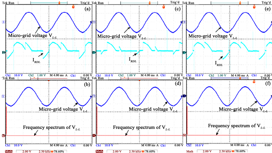
Figure 13. Power quality performances of the isolated micro-grid system with the application of the active power controller: (a) Voltage and current flowing into dump load; (b) Voltage and frequency spectrum of the voltage; (c) Voltage and current flowing into the dump load with a step increase in load demand; (d) Voltage and frequency spectrum of the voltage with a step increase in load demand; (e) Voltage and current flowing into the dump load with a step decrease in load demand; (f) Voltage and frequency spectrum of the voltage with a step decrease in load demand.
shown in Figure 13(b). The frequency spectrum only shows the fundamental component of the micro-grid voltage. Figure 13(c) shows micro-grid voltage and current flowing into the dump load while micro-grid load demand is increased. Due to the increase in micro-grid load demand, current flowing into the dump load is also reduced. Moreover, the frequency spectrum during this operational condition also shows only the presence of fundamental component of the micro-grid voltage. The similar frequency spectrum is also noticed, while the micro-grid load demand is decreased. The presence of only fundamental frequency component in the micro-grid voltages ensures the high quality power in the isolated micro-grid system.
6. Conclusion
This paper has presented the development, implementation and performance testing of an active power controller for an isolated micro-grid system. The controller is developed based on alternating current control technique, where dump load resistor and power-frequency droop characteristics are employed. A micro-grid test bench is developed that comprises the key development of a wind turbine simulator. In addition, the other factors in the micro-grid test setup are considered based on the scope and availability of the equipments and facilities in the lab. Such test setup is utilized to test the performances of the developed active power controller. The developed controller is implemented using dSPACE ds1104 DSP board along with other equipments described in the paper in details. The performance results presented in the paper show the ability to maintain the fast and accurate power balance between the generation and load, while a stable and reliable operation was maintained during transition between the grid connected to the isolated micro-grid domain, and in the subsequent operation. More- over, the power quality results also show the ability to generate and deliver quality power to the micro-grid load.
Acknowledgements
This work is supported by a research grant from the National Science and Engineering Research Council (NSERC) of Canada, the Atlantic Innovation Fund (AIF) Canada, and Memorial University of Newfoundland. The authors would like to acknowledge the utility company, Newfoundland Power, Canada for providing the system information and data.
References
- Mahat, P., Chen, Z. and Bak-Jensen, B. (2010) Under Frequency Load Shedding for an Islanded Distribution System with Distributed Generators. IEEE Transaction on Power Delivery, 25, 911-918. http://dx.doi.org/10.1109/TPWRD.2009.2032327
- Katiraei, F. and Iravani, M. (2006) Power Management Strategies for a Micro-Grid With Multiple Distributed Generation Units. IEEE Transaction on Power Systems, 21, 1821-1831. http://dx.doi.org/10.1109/TPWRS.2006.879260
- Lasseter, R.H. (2002) Micro-Grids. IEEE Power Engineering Society Winter Meeting, New York, January 2002, 305- 308.
- Lasseter, R.H., Eto, J.H., Schenkman, B., Stevens, J., Vollkommer, H., Klapp, D., Linton, E., Hurtado, H. and Roy, J. (2011) CERTS Micro-Grid Laboratory Test Bed. IEEE Transaction on Power Delivery, 26, 325-332. http://dx.doi.org/10.1109/TPWRD.2010.2051819
- Ahn, S., Park, J., Chung, I., Moon, S., Kang, S. and Nam, S. (2010) Power-Sharing Method of Multiple Distributed Generators Considering Control Modes and Configurations of a Micro-Grid. IEEE Transaction on Power Delivery, 25, 2007-2016. http://dx.doi.org/10.1109/TPWRD.2010.2047736
- Ribeiro, L.A.deS., Saavedra, O.R., Lima, S.L.de. and Matos, J.G.de. (2011) Isolated Micro-Grids with Renewable Hybrid Generation: The Case of Lenis Island. IEEE Transaction on Sustainable Energy, 2, 1-11.
- Georgakis, D., Papathanasiou, S.A., Hatziargyriou, N., Engler, A. and Hardt, Ch. (2004) Operation of a Prototype Micro-Grid System Based on Micro-Sources Equipped with Fast-Acting Power Electronics Interfaces. Power Electronics Specialists Conference, 4, 2521-2526.
- Kojima, Y., Koshio, M., Nakamura, S., Maejima, H., Fujioka, Y. and Goda, T. (2007) A Demonstration Project in Hachinohe: Micro-Grid with Private Distribution Line. IEEE International Conference on System of Systems Engineering, San Antonio, 16-18 April 2007, 1-6.
- Katiraei, F. and Iravani, M.R. (2005) Transients of a Micro-Grid System with Multiple Distributed Energy Resources. International Conference on Power Systems Transients (IPST’05), Montreal, 19-23 June 2005, Paper No. IPST05-080.
- Katiraei, F., Iravani, M.R. and Lehn, P.W. (2005) Micro-Grid Autonomous Operation during and Subsequent to Islanding Process. IEEE Transaction on Power Delivery, 20, 248-257. http://dx.doi.org/10.1109/TPWRD.2004.835051
- Shahabi, M., Haghifam, M.R., Mohamadian, M. and Nabavi-Niaki, S.A. (2009) Microgrid Dynamic Performance Improvement Using a Doubly Fed Induction Wind Generator. IEEE Transaction on Energy Conversion, 24, 137-145. http://dx.doi.org/10.1109/TEC.2008.2006556
- Majumder, R., Ghosh, A., Ledwich, G. and Zare, F. (2009) Load Sharing and Power Quality Enhanced Operation of a Distributed Micro-Grid. ET Renewable Power Generation, 3, 109-119. http://dx.doi.org/10.1049/iet-rpg:20080001
- Ahshan, R., Iqbal, M.T., Mann, G.K.I. and Quaicoe, J.E. (2014) Control System Development and Test for the Operation of a Micro-Grid System―PART I. Smart Grid and Renewable Energy Journal, 5, 291-301.