Energy and Power Engineering
Vol. 4 No. 6 (2012) , Article ID: 24997 , 6 pages DOI:10.4236/epe.2012.46052
UP-Gradation of Power System Protection Scheme through TCP/IP Using GUI*
Department of Electrical Engineering COMSATS, Institute of Information Technology, Abbottabad, Pakistan
Email: qamar_raza786@yahoo.com, Naumantareen@ciit.net.pk
Received June 14, 2012; revised July 17, 2012; accepted July 29, 2012
Keywords: Power System Protection Scenario (PSPS); TCP/IP; Graphical User Interface (GUI)
ABSTRACT
The paper is concerned with the Power System Protection schemes and the resulting design requirement that enhances stability as well as control with the implementation of TCP/IP. It discusses the architecture that upgrades the existing scheme by controlling all the control signals traffic between generating units, transmission system, connected loads and protection devices that are sensitive to control signals using TCP/IP and results are compared using Graphics User Interface (GUI) in MATLAB/Simulink. Protection system describes latest breakers circuit using indirect tripping command from generating units that protects load side through load breakers that receives action signal from local controllers that have a direct communication linkage with main server having strong data base, directly monitors everything through TCP/IP platform using GUI.
1. Introduction and Background
To restore the system to a normal state and minimize the impact of the disturbances, the protection and control actions are required to stop the power system degradation, when a major power system disturbance occurs. Presently the control actions are not designed for a fast-developing disturbance and are too slow. Local protection systems are not able to account the overall system, which may be affected by the disturbance. System wide disturbances in power systems are growing issue for the power system industry [1-6]. The concept of wide area disturbance protection is to use the system-wide information and sending selected local information to a remote location to counteract propagation of the major disturbance in the power system. To restore the system to a normal state, and minimize the impact of the disturbance [7,8]. The system-wide disturbance protection is the ability to receive system-wide information and commands through the data communication system.
The comparative importance of each region vulnerability is known as the vulnerability index. The maximum value of vulnerability index shows that the region is comparatively more important and can cause more serious wide area disturbances or has a higher possibility to cause the disturbances than the one with a minimum index value.
The wide area protection schemes, also called Remedial Action Scheme is designed to detect the abnormal conditions in the system and take pre-planned, corrective action to provide acceptable system performance [1]. In the area of power system automation and substation automation, there are two different trends one is the centralization and the other is decentralization. More and more dynamic functions [9] are moving from local and regional control centers towards central or national control centers. At the same time we also observe more intelligence and decision-power converges towards the original power system substations. Such action includes, among others, changes in demand, changes in generation or system configuration to maintain system stability and specific actions to maintain acceptable voltage levels [10]. The decision and corrective actions need fast communication link to collect data and/or to initiate actions [1,11].
This paper is divided into four main sections. The first section of the paper describes the performance of protection schemes in the power systems and presenting the need for the power system protection schemes and the resulting design requirements. The second section discussed the TCP/IP applications in wide area networks (WAN) and in local area networks (LAN). Third section includes the protection schemes cases in the TCP/IP environment. Finally the analysis and design of power system protection schemes (PSPS) in graphics user interface (GUI) environment will be discussed.
2. Power System Protection Schemes
The behavior of protection functions during dynamics operating conditions that were not considered during the normal relay setting process and provides solutions to prevent undesirable relay performance during system-wide disturbance [2,11]. Several salient points are discussed for the following protection schemes:
• Transmission line protection
• Transformer protection
• Generator protection
• Bus protection
• Shunt reactor/capacitor protection
• Feeder protection
• Motor protection
• Load shedding Most of the modern relay schemes are microprocessor relays [2], phasor measurements [12,14] are affected by inputs at off-nominal frequencies. Frequency tracking/ compensating schemes used in these relays may or may not track the fast changing system frequency [13]. The impact of the frequency deviation from the nominal is discussed with each type of protection. For example, distance relay algorithm or operating principles make use of memory polarization. Memory polarization uses several cycles of pre fault voltages to ensure correct relay operation for faults that causes voltages to dip below a threshold or for faults on series compensated lines resulting in voltage inversion [4-6,9]. The longer the memory duration, the higher is the risk of undesired tripping during off nominal [9] frequency operation. The character of legacy systems under off-nominal frequency is dictated by their designs.
The angular instability [12] causes large power swings leading to under-voltage [15] and under-current situations in the system. Distance relays are prone to respond to unstable swings resulting in unwanted tripping at undesirable locations in the system resulting in severe generation-load imbalance [10]. It is desirable to block tripping at some locations and to permit tripping at some other locations in order to maintain system stability.
Modern relays are equipped with load encroachment logic to prevent operation due to loads. High power transfers heavy loading during system stressed conditions may result in load impedance encroaching into the impedance characteristics of overreaching distance relays resulting in undesired line tripping and make worse the overall system stability. Over voltages during system stressed conditions may result in excessive fifth harmonics current that may operate differential relays not equipped with fifth harmonic restraint. Excessive loading of transformers may also result in the operation of over current relays set at levels with less over load margin.
Generators are protected against overloads [10], abnormal frequency and voltage operations. Improper coordination of protective relays has resulted in tripping of generators during system disturbance. The bus protection schemes are based on differential principle, they are generally immune to severe system disturbances. Shunt capacitor bank protection is sensitive to severe unbalance currents and harmonics present during a disturbance. The uncontrolled tripping of feeders will result in larger generation or load imbalance aggravating the disturbance.
3. TCP/IP Application in LAN and WAN Scenario
The Transmission Control Protocol (TCP) and the User Datagram Protocol (UDP) are both IP transport-layer protocols. UDP is a lightweight protocol that allows applications to make direct use of the unreliable datagram service provided by the underlying IP service. UDP is commonly used to support applications that use simple query/response transactions, or applications that support real-time communications. TCP provides a reliable datatransfer service, and is used for both bulk data transfer and interactive data applications. TCP is the major transport protocol in use in most IP networks, and supports the transfer of over 90 percent of all traffic across the public Internet today. Given this major role for TCP, the performance of this protocol forms a significant part of the total picture of service performance for IP networks.
All the functionality required to take a simple base of IP datagram delivery and build upon this a control model that implements reliability, sequencing, flow control, and data streaming is embedded within TCP. TCP is a fullduplex protocol; it allows both parties to send and receive data within the context of the single TCP connection. TCP is also a rate-adaptive protocol, in that the rate of data transfer is intended to adapt to the prevailing load conditions within the network and adapt to the processing capacity of the receiver as shown in Figure 1.
This protocol exchange offers acceptable performance. This protocol exchange for a single data character and its echo occurs within about 16 ms on an Ethernet LAN, corresponding to an interactive rate of 60 characters per second. When the network delay is increased in a WAN, these small packets can be a source of congestion load. The WAN application process data taken from the modern power station share this information with the substation through TCP/IP processed by LAN application as shown in Figure 2.
4. Proposed Protection System Using TCP/IP
The requirements for a wide area network protection system using TCP/IP can vary from one utility company to another; the architecture for such a system must be
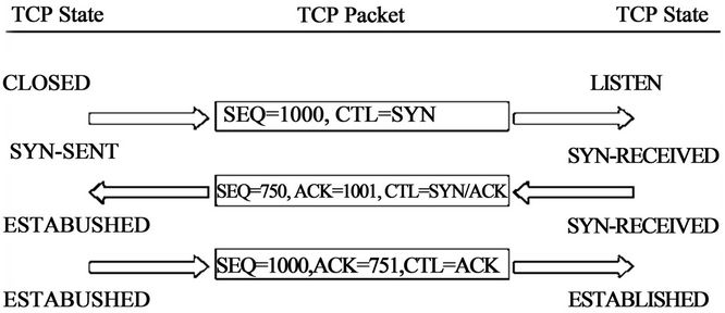
Figure 1. TCP connection handshake.
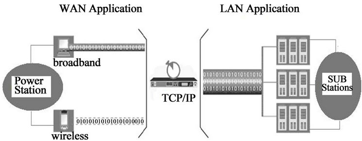
Figure 2. WAN and LAN application through TCP/IP.
designed according to what technologies a utility possesses at the given time. The grid company can extend the system operational limits, i.e. operate the system closer to the natural constraints, maximizing return on investments in high voltage equipment. The utility needs and problems are often formulated in very loose terms, such as intelligent load shedding, protection system against major disturbances, and counteract cascaded line tripping. These needs have to be broken down to physical phenomena, such as protection against the transient angle instability, small signal angle instability, frequency instability, short term voltage instability, long term voltage instability, cascading outages.
The operator has all vital information (i.e. from the data base) at his finger tips and good analysis facilities; he can operate the grid in an efficient manner. With the help of better analysis tool for voltage instability, the operator can accurately track the power margin across an interface, and thus can confidently push the limit of transfer across an interface. SCADA using TCP/IP communication facilities has highly extended data handling capabilities. Transducers such as the PMUs can provide time-synchronized measurements from all over the grid as shown in Figures 3 and 4. Based on these measurements, improved state estimators can be derived.
Different kinds of intelligent load shedding can be ordered more or less automatically from the SCADA using TCP/IP system in case of energy shortage on the electricity market or other limitations in the power system operation, that can be planned in advance. With access to wide area measurements, such a system can be made adaptive to cope with actual system conditions, such as load flow pattern and voltage levels as shown in Figure 5.
5. Proposed Analysis and Design of Protection System Using Graphics User Interface (GUI)
The overall alter in the voltage and current waveform indicates type of fault (e.g. phase A to ground). It also points to other characteristics of the fault and the behavior of the protection system (fault clearing, reclosing). Events and protection system operation analysis includes the following checks:
• Relay and breaker contacts state is tested for a change. A status alter is an indication that the protection system has detected a fault.
• If the protection system operation is detected and the presence of a fault is not identified. It is an indication of a protection system missed operation.
• If a fault is detected and there is no protection system
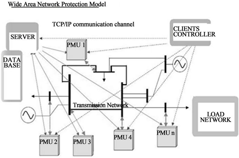
Figure 3. Wide area network model.
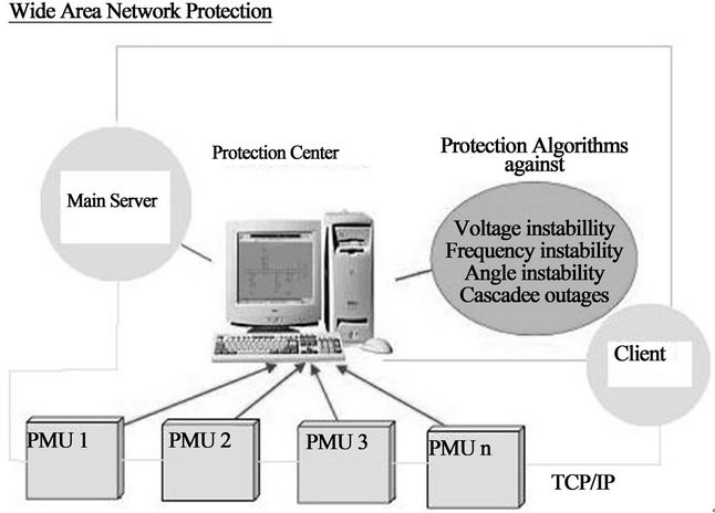
Figure 4. Wide area network protection.
operation. It is an indication of a possible protection system failure.
The specialized system block diagram is shown in figure. The data conversion block translates the format of data generated by the EMTP (electromagnetic transient program) and different DFRs (digital fault recorders) into a format suitable for analysis performed by a commercial signal-processing package, MATLAB. Additional substation description interface through TCP/IP is developed to make up for insufficient EMTP/DFR configuration data. A MATLAB program analyzes raw data to provide parameters required for the diagnostic process. CLIPS, an expert system shell, take data from MATLAB to make final conclusions regarding the fault detection and diagnosis. EMTP is used to generate test data through simulation, while DFRs are used to collect actual data in a substation. MATLAB identifies incidence of circuit breaker and relay change of status as protection system parameters. It also analyzes the communication signal operation intervals to identify the communication protection system parameters. The GUI screens serve as final expert system output as shown in Figure 6.
There are several different levels of information that are given through GUI. This information includes a complete step-by-step reasoning process performed by the CLIPS shell, as well as a plot of voltage and current wave forms for transmission line experiencing disturbance, including circuit breaker and communication channel contacts.
The communication between the expert system computer (ESC) and the substation DFR is facilitated using TR1625 master station software. Every recorded event at the substation is retrieved and archived at the ESC. Upon completed retrieval of an event, classification and analysis are executed, and the report is generated and stored. The report consists of textual description of an event and of graphical files. These graphical files are processed using MATLAB 7.8 and converted into standard encapsulated postscript (EPS, which is used for printing) and PC paintbrush (PCX) forms. The ESC, in this case, serves as a host machine.
The ESC will be located at the substation, and the link to region A will eliminate to exist. When that happens, short messages will be sent to region B through TCP/IP channel as shown in Figure 7. This will replace the existing practice in which a stream of recorded data is sent from the substation to region B once an operator dial-up call from region B offices.
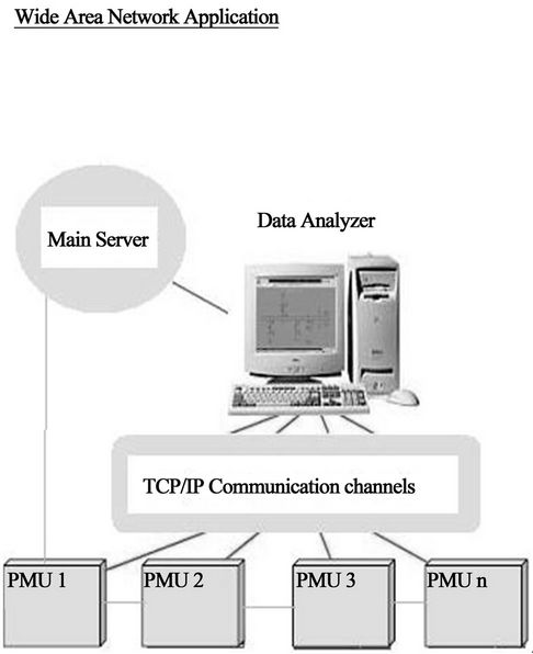
Figure 5. Wide area network application.
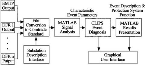
Figure 6. Proposed model in MATLAB.
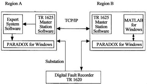
Figure 7. TCP/IP interface between substations.
6. Conclusion
The paper concludes that the power system protection system implementation over a wide area is often required to keep the present power system integrity. It discusses the architecture that upgrades the existing scheme by controlling protection devices that are sensitive to control signals using TCP/IP and results are compared using Graphics User Interface (GUI) in MATLAB/Semolina. Protection system that receives action signal from local controllers that have a direct communication linkage with main server having strong data base, directly monitors everything through TCP/IP platform using GUI.
REFERENCES
- IEEE Power System Relaying Committee, “Global Industry Experiences with System Integrity Protection Schemes (SIPS),” 2009. www.Pes-psrc.org
- M. Begovic, “Wide Area Protection and Emergency Control,” Power Systems Conference and Exposition, 10-13 October 2004, pp. 1776-1777.
- FERC, US/Canada Power Outage Task Force, “Initial Blackout Time-Line,” 2003. www.ferc.gov
- S. H. Horowitz and A. G. Phadke, “Boosting Immunity to Blackouts,” Power Energy Magazine, Vol. 1, No. 5, 2003, pp. 47-53. doi:10.1109/MPAE.2003.1231691
- D. Novosel, M. Begovic and V. Madani, “Shedding Lights on Blackouts,” IEEE Power Energy Magazine, Vol. 2, No. 1, 2004, pp. 32-43. doi:10.1109/MPAE.2004.1263414
- I. Dobson, J. Chen, J. S. Thorp, B. A. Carreras and D. E. Newman, “Examining Criticality of Blackouts in Power System Models with Cascading Events,” Proceedings of the 35th Annual Hawaii International Conference on System Sciences, 7-10 Janaury 2002, 10 p.
- M. Begovic, V. Madani and D. Novosel, “System Integrity Protection Systems,” IREP Symptom Bulk Power System Dynamics and Control VII, Charleston, August 2007.
- V. Madani and D. Novosel, “Getting a Grip on the Grid,” IEEE Spectrum, Vol. 42, No. 12, 2005, pp. 42-47. doi:10.1109/MSPEC.2005.1549781
- WECC, “Technical Studies Subcommittee. Load Shedding and Restoration Program,” 1997 and 2004.
- P. Anderson and B. K. L. Reverend, “Industry Experience with Special Protection Schemes,” IEEE Transactions on Power Systems, Vol. 11, No. 3, 1996, pp. 1166- 1179.
- Y. Ohura, M. Suzuki, K. Yanagihashi, M. Yamaura, K. Omata, T. Nakamua, S. Mitamura and H. Watanabe, “A Predictive Out-of-Step Protection System Based on Observation of the Phase Difference between Substations,” IEEE Transactions on Power Delivery, Vol. 5, No. 4, 1990, pp. 1695-1704. doi:10.1109/61.103664
- V. Madani, E. Taylor, D. Erwin, A. Meklin and M. Adamiak, “High Speed Control Schemes to Prevent Instability of Large Multi-Unit Power Plant,” Western Protection Relay Conference, Spokane, 27-29 March 2007, pp. 271- 282.
- V. Madani, D. Novosel, M. Begovic and M. Adamiak, “Application Consideration in System Integrity Protection Schemes (SIPS),” GE Magazine, 2008, pp. 2-8.
- T. Ohno, et al., “Islanding Protection System Based on Synchronized Phasor Measurements and Its Operational Experiences,” IEEE on Power and Energy Society General Meeting—Conversion and Delivery of Electrical Energy in the 21st Century, Pittsburgh, 20-24 July 2008, pp. 1-5.
- S. Imai, “Under Voltage Load Shedding Improving Security as Reasonable Measure for Extreme Contingencies,” IEEE on Power Engineering Society General Meeting, San Francisco, 12-16 June 2006, pp. 1754-1759.
NOTES
*In MATLAB (Simulink).