Energy and Power Engineering
Vol.11 No.08(2019), Article ID:94372,17 pages
10.4236/epe.2019.118019
A Reliability-Based Strategy for the Analysis of Single Proton Exchange Membrane Fuel Cells
Patricia da Silva Pagetti de Oliveira*, Vinicius Andrea, Elisabete Inacio Santiago, Thiago Lopes, Delvonei Alves de Andrade, Marcelo Linardi
Nuclear and Energy Research Institute, IPEN-CNEN/SP, São Paulo, Brazil

Copyright © 2019 by author(s) and Scientific Research Publishing Inc.
This work is licensed under the Creative Commons Attribution-NonCommercial International License (CC BY-NC 4.0).
http://creativecommons.org/licenses/by-nc/4.0/


Received: May 7, 2019; Accepted: August 13, 2019; Published: August 16, 2019
ABSTRACT
The development of power conversion systems based on fuel cells has been demanding reliability studies since the requirements associated with cost and durability of these technological products have become fundamental to their acceptance by the energy market. The experimental part of the reliability study presented in this work consisted of performing life tests with single proton exchange membrane fuel cells (PEMFCs). The proposed reliability analysis methodology covered the application of qualitative and quantitative techniques. In the qualitative approach, a Failure Mode and Effect Analysis was developed in order to identify and evaluate all potential failures associated with the operation of fuel cells. In the quantitative approach, a statistical analysis was applied to the sample data generated in long-term steady-state tests of these devices. A two-parameter exponential distribution was fitted to data and the maximum likelihood estimate for the mean time to failure (MTTF) of the fuel cells was calculated. It is important to point out that the tests performed under the scope of this study were the first long-term experiments performed with the fuel cells produced in the laboratories of IPEN-CNEN/SP, Brazil. Although the results indicated that fuel cell performance and durability were still at a level below the targets normally established for similar commercial devices, the improvement of the main components of PEMFCs has been the objective of several projects developed at the institute. Thus, the main benefit brought by this study is the proposed methodology, which can be implemented as part of a reliability growth analysis of the fuel cells and can be integrated into the design process of these devices.
Keywords:
Fuel Cells, Reliability, Durability, Performance, Life Tests, Lifetime, Failure-Time

1. Introduction
The increasing global concern with the environment and climate changes has been encouraging scientists and energy companies to search low impact energy sources, high efficiency power generation systems and low polluting automotive vehicles. Therefore, this scenario has been favorable to the maturing process of the so-called “hydrogen economy”, in which the concept of the energy conversion system known as “fuel cell” is inserted. Fundamentally, fuel cells are gas fed batteries, i.e. devices that convert chemical energy directly into electrical and thermal energy by the electrochemical combustion of a fuel, usually hydrogen. However, unlike a battery, the reactants in a fuel cell are stored externally and supplied continually. For larger scale applications, fuel cells have several advantages over batteries, including smaller size, lighter weight, quick refueling, and longer range [1] .
Nowadays, the United States of America, Japan, Canada and some European Union countries carry out important programs in this area and establish well defined targets in relation to the application of hydrogen and fuel cell technology to transportation (cars, buses, trains, spaceships, forklifts, etc.), stationary power (low to moderate power level) and portable power (computers, cell phones, etc.). Regarding Brazil, it is expected that this technology, which is associated to a low pollutant emission and high efficiency use of fuel, may take an important role in the planning of its national energy matrix [2] .
Significant scientific progress in fuel cell technology has been achieved over the past few decades, mainly in relation to system efficiency, fuel diversity and operational flexibility [3] [4] [5] [6] . Nevertheless, durability and cost have been identified as the top two issues still challenging the success of this technology. On the one hand, it is recognized that only when fuel cell costs are dramatically reduced to the target of the United States Department of Energy (US DOE) of $30 kW−1 will fuel cells be competitive for virtually every type of power application. On the other hand, to reach technological readiness, automotive fuel cell power systems need to be as durable as today’s internal combustion engines, corresponding to a 5000-hour operating lifetime (approximately 7 months over a range of vehicle operating conditions), and stationary fuel cells must also meet operating lifetime targets of more than 60,000 hours (approximately 6.8 years of continuous operation) to compete with existent distributed power generation systems, based on the 2016 US DOE targets at component, stack, and system levels. The US DOE durability targets for transportation and stationary fuel cell applications stand on the lifetimes of energy conversion devices that are competitive with fuel cells, such as internal combustion engines and micro turbines, respectively. However, the lifetimes of fuel cell vehicles and stationary cogeneration systems are currently around 3900 hours and 12,000 hours, respectively [7] .
These values show that, in order to achieve the proposed objectives, future developments are necessary [8] . In addition, current knowledge on the reliability of proton exchange membrane fuel cells (PEMFCs) is still in the early stages of development and further research aimed at promoting the commercialization of this device should be promoted [9] . It should be noted that studies on reliability techniques applied to PEMFC systems are limited in the literature and analysis strategies may vary depending on the operating conditions of the device, such as those discussed in this work [10] .
This work aims to describe the adopted methodology and to present the main results regarding the reliability study of single PEMFCs that have been produced in the laboratories of IPEN-CNEN/SP, Brazil. In this case, a broad and complete methodology to analyze the reliability of PEMFCs was defined. Thus, it is worth emphasizing the importance of considering two main stages for the development of the analysis: an initial qualitative evaluation of the factors that contribute to fuel cell failure; and a stage of life tests, whose protocols were established based on local practices. In addition, this methodology allows the evolution of the fuel cell design to be monitored and compared with the results of previous tests.
2. Methodology
2.1. Reliability Analysis
In industry, the concept of reliability is usually associated with the quality requirements of a product and intrinsically covers the aspects of durability, maintainability and safety. Improving product reliability is an important part of the overall picture of improving its quality. Concerning fuel cells, special emphasis may be given to the aspect of durability, which is the capability of these devices to resist a permanent degradation in performance and can be considered a measure of their useful lifetime.
Concerning the technical definition, reliability is the probability of an item to perform its specified function adequately in the designated environment and for a determined period of time or number of cycles/events [11] . This is the most widely accepted definition of reliability and it implies that some important elements must be identified:
· the specified function of the item;
· the meaning of an adequate performance of the item;
· the environmental and operating conditions in which the item shall function; and
· the period of time or number of cycles/events in which the item shall function adequately. This period of time or number of cycles/events usually refers to the mission time/cycle of the item.
Several techniques can be used in the reliability study of an item, ranging from a qualitative analysis, in which critical failures of this item can be identified and evaluated, to a statistical analysis of lifetime data, for predicting and assessing various quantities of interest regarding item reliability. In this article, the single PEMFC was considered a device.
The initial stage of the reliability study discussed in this work consisted of the identification of all potential failures associated with the operation of single PEMFCs. The technique applied in this stage was a Failure Mode and Effect Analysis (FMEA), which is an inductive, systematic and detailed method of identifying all possible failures of a product/process, investigating failure causes, evaluating failure effects, checking existing resources for failure detection and control, and defining preventive/corrective actions that could eliminate the causes or mitigate the undesirable effects of failures [11] [12] . A formal FMEA process may be a part of a comprehensive quality control system since it is a technique quoted in ISO 9004, which has an equivalent standard in Brazil, named ABNT NB-9004 [13] . This method has not been commonly applied in fuel cell reliability studies, at least not integrated to the life-testing stage as it was done in this work, to obtain both qualitative and quantitative data on the performance of these devices. Therefore, a FMEA was developed to identify failures related to the operation of the PEMFCs and some studies published in the literature that addressed degradation mechanisms and failures of major components of these devices were taken into consideration [14] - [22] . It is important to mention that many factors can affect the performance and durability of fuel cells, such as: environmental conditions, operating conditions, system operating modes, configuration of fuel cell components, materials used in fuel cell composition, manufacturing process, assembly process, presence of impurities or contaminants in the process, human factors, etc. All these factors were evaluated during the development of the FMEA for the PEMFCs. Thus, after FMEA development, it was possible to conclude that the most critical failures of PEMFCs are chemical degradation of the membrane, degradation of the catalytic layer and carbon corrosion of the surface of graphite plates.
The main purpose of starting the reliability study with a qualitative analysis before the experiments in the laboratory were performed was to promote familiarization with the phenomena involved during the operation of the PEMFCs, including the formation of a theoretical basis on the failure mechanisms that could occur during life tests. It is important to mention that some effects of component failures evaluated by the FMEA, regarding the performance of the fuel cells, are not directly identified during a test. In this case, it is necessary that the fuel cells be dismantled and diagnostic techniques be applied so that they can be diagnosed. In the present study, only the polarization curve was considered, since it did not require the dismantling of the fuel cells. Other diagnostic techniques, such as cyclic voltammetry, electrochemical impedance spectroscopy, etc., were applied to the fuel cells used during the tests, but were not part of the scope of this reliability study.
In the quantitative stage of the reliability study of the PEMFCs, two different approaches were adopted: 1) analysis of performance data, based on the records of fuel cell voltage and power density as a function of time; and 2) analysis of failure times (or lifetime data), that covered the aspect of fuel cell durability [23] [24] [25] . In general, the collection of lifetime data is extracted from sources such as: laboratory tests on early prototype units; operating records of early production units in the field; and records of systematic longer-term tracking of products in the field [11] [23] . Considering that field data of this type of product were not available, reliability data needed to be obtained from life tests, also known as reliability/durability tests.
Determining the number of required tests, i.e. the appropriate sample size to evaluate the reliability of fuel cells, is an important issue and should not be omitted in the discussion and interpretation of the analysis results. In general, the sample size is determined based on the accuracy that is desired in the reliability measures of the devices. However, it is very common for constraints involving test time and experiment conditions that the sample size obtainable be reduced. Thus, the representativeness of the sample to fulfill the objectives of the study shall be discussed in the presentation of the final results. In the life tests performed to generate sample data, actual operating conditions of the fuel cells, both stable and dynamic, could be simulated in the test stations. The end of test criterion adopted for the fuel cell life tests was: if the fuel cell voltage went below a pre-defined minimum value, the test had to be stopped and a failure of the device would be characterized. The period of time up to the moment of this occurrence would be recorded as a failure time. Thus, a minimum voltage of 0.3 V was defined based on the harmful or catastrophic effect generated by this condition in the system and to avoid irreversible damage of the cell components. In addition, in some cases, the test was terminated due to time constraints imposed on test duration or due to the occurrence of a failure that was not of primary interest for the study. Hence, two types of censoring mechanisms were observed in the reliability data analysis: “time censoring”, when unfailed units were removed from test at a predetermined time; and “random right censoring”, when units failed from causes that were not of primary interest for the study, e.g. failure of some test station item, failure in the supply of reactant gases, etc. Both censoring mechanisms contributed to the generation of a set of “right-censored data”, that is, the exact failure times of some units were not determined, but they were known to be greater than the censoring time. At any rate, these incomplete or partial data should not be neglected when estimating reliability parameters.
The first part of the statistical analysis of lifetime data obtained from tests consisted of the application of descriptive methods for assessing fuel cell performance as a function of time [26] [27] [28] [29] . Therefore, for each test unit, polarization curves (fuel cell voltage vs. time and fuel cell power density vs. time) were constructed and fuel cell degradation was evaluated by means of the following performance measures over a selected period of time: mean and standard deviation of the fuel cell voltage (mV); voltage decay rate (mV·h−1); percentage of the voltage loss at the end of the test (%); mean and standard deviation of the fuel cell power density (mW·cm−2); power density decay rate (mW·cm−2·h−1); percentage of the power density loss at the end of the test (%).
The second part of the statistical analysis of lifetime data obtained from tests consisted of a failure-time analysis [23] [24] [25] , which was carried out by means of two different approaches: the nonparametric estimation of the fuel cell reliability function; and the parametric modeling of failure-time data using a known probability distribution. The nonparametric estimation is a model-free tool for reliability data analysis, which involves analytical and graphical techniques that do not require strong model assumptions. Such techniques allow the singly right-censored data (failure times and censoring times) obtained from the tests to be used to calculate estimates and confidence limits for the fuel cell failure-time distribution function. In the parametric analysis, a well-known probability distribution, suitable to model failure-time processes, may be adjusted to data obtained from the tests. In this case, the most commonly used parametric probability distributions are exponential, Weibull, gamma, lognormal and normal. After fitting the most appropriate model, its parameters and some important functions of the parameters were estimated, and quantities of interest such as mean lifetime (or mean time to failure), distribution quantiles and failure rate of the fuel cells were calculated. For research purposes, it is important and useful to compare the results obtained from both parametric and nonparametric analyses of the same data set.
2.2. Experimental Procedures
The production of MEAs and the assembly of single PEMFCs can be made by using various techniques and several types of materials in their composition. An optimization of the process for the production of MEAs based on the sieve printing method has been implemented at IPEN-CNEN/SP laboratories [30] and the test units used in this study were produced by this process.
Firstly, DuPont™ Nafion® N115 membranes were treated in hydrogen peroxide solution (3% v/v) at 80˚C for 1 hour to eliminate organic impurities, followed by rinsing with water in the same conditions to remove H2O2 traces. Then, the membranes were treated with sulphuric acid 0.5 mol·L−1 solution at 80˚C for 1 hour, with subsequent washing in water to eliminate acid residues. Catalyst layers of gas diffusion electrodes (GDE) for single PEMFCs were prepared as described in [30] , considering that the application of the catalyst ink to the surface of the diffusion layer of each electrode (anode and cathode) was made by the painting method called sieve printing. In all cases, 35.5 wt% of Nafion® (5 wt% solution in a mixture of alcohols, DuPont), which corresponds to 1.1 mg·cm−2, was applied to the catalyst layer. The total metal loading (Pt/C 20 wt% Pt, BASF) ranged from 0.40 to 0.56 mg·cm−2 for the anodes and from 0.60 to 0.85 mg·cm−2 for the cathodes. The gas diffusion layer (GDL) consisted of a carbon cloth wet-proofed with Teflon® (ElectroChem). The membrane electrode assemblies (MEAs) were fabricated by hot pressing the anode and the cathode to the electrolyte membranes at 125˚C and 1000 kgf·cm−2 for 2 minutes. The main features of the fuel cells tested in this study are summarized in Table 1.
Life tests were carried out in order to generate the sample data required for the performance evaluation and durability estimation of the fuel cells. The experiments were executed in two automated test stations Evaluator C10-LT, manufactured by FuelCon.

Table 1. Main features of the single PEMFCs produced for this study at IPEN-CNEN/SP laboratories.
The tests were divided into two main groups: 1) tests performed in stable operating conditions in order to determine the evolution of cell voltage as a function of time at a fixed current density, also called long-term steady-state tests; and 2) tests performed in dynamic operating conditions in order to determine the evolution of cell voltage as a function of the current density following an on/off profile versus time, also called accelerated (or ageing) life tests. Accelerated life tests are tests in which the stress applied to the item exceeds its nominal operating conditions so as to shorten the time required for failure occurrence.
In both cases, that is in the steady-state or accelerated life tests, the proposed test protocols were based on protocols recommended by regulatory agencies [23] [24] [25] .
The main steps of these test protocols were: system start up and fuel cell heating; fuel cell voltage cycling; conditioning of the fuel cell during a 24-hour period; performance of the initial polarization curve; long-term steady-state test or accelerated on-off cycling test; performance of the final polarization curve; and system shutdown.
System parameters such as reactant gas (fuel and oxidant) temperature and flow rate, humidifier (anode and cathode) temperature, fuel cell temperature, system pressure, etc., were adjusted during the development of the experiments, and the ideal conditions for the operation of a 25 cm2-area single PEMFC for long term tests were considered.
The process variables controlled during the life tests are presented in Table 2. Operating conditions indicated in Table 2 were expected to remain stable during all the measurement steps.
Among the various tests performed, seventeen were considered valid and relevant to this study. Thirteen life tests were performed with the fuel cells operating at stable conditions (steady-state), ten of which were interrupted due to constraints on test duration and three were terminated after the occurrence of a failure in the system. Among the four accelerated life tests, one was interrupted due to constraints on the number of cycles (500 cycles) and three tests were terminated after the occurrence of a failure in the system.
The main criteria used to determine the validity of a test were: reproducibility during the manufacture and assembly of the fuel cells and repeatability of test conditions. Thus, the tests that were eliminated from this study did not meet these requirements satisfactorily. The results to be presented in the following section correspond to the statistical analysis of the reliability data generated from the valid long-term steady-state tests.
3. Results and Discussion
According to the analysis methodology proposed for this study, sample data obtained from the long-term steady-state tests of the PEMFCs were compiled and the results were divided into two main groups:
1) performance of the fuel cells, associated with the observed measures of fuel cell voltage and power density over selected periods of time; and
2) durability of the fuel cells, associated with the failure/censoring times observed during the tests.
Table 2. System operating conditions during the life tests of single PEMFCs.
Concerning the fuel cell performance during the tests, which was assessed by the measures of voltage and power density over selected periods of time, it can be shown that the percentage of voltage loss at the end of the test varied within the range from 2.59% to 93.12%, and most values were within the range from 3.00% to 8.00%. The complete set of data is given in Table 3 and the most relevant results are described as follow. The median value of the percentage of voltage loss was 6.33%. The voltage decay rate of the fuel cells varied within the range from 0.04 to 1.30 mV·h−1 (40 to 1300 µV·h−1). Most values (67%) were below 0.10 mV·h−1 (100 µV·h−1), and the median value of the voltage decay rate was 0.08 mV·h−1 (80 µV·h−1). The percentage of power density loss at the end of the test varied within the range from 0.42% to 88.33%, with most of the values below 6.54%. The median value of the percentage of power density loss was 4.84%.
The power density decay rate of the fuel cells varied within the range from 0.004 to 0.79 mW·cm−2·h−1 (4 to 790 µW·cm−2·h−1). Most values (67%) were below 60 µW·cm−2·h−1 and the median value was 0.05 mW·cm−2·h−1 (50 µW·cm−2·h−1).
Some graphical results obtained from the life tests in which the fuel cells were operated at fixed current and stable conditions (long-term steady-state tests) are illustrated in Figures 1-4.
Figure 1 and Figure 2 correspond to the observed performance along time (fuel cell voltage vs. time) of the units named Cel 1 MEA 11 and Cel 1 MEA 12, respectively.
Table 3. Results of the long-term durability tests and correspondent median values.

Figure 1. Single PEMFC performance (voltage vs. time) at fixed current, 75˚C, 100% RH, 1 atm, H2/O2—Test unit Cel 1 MEA 11.
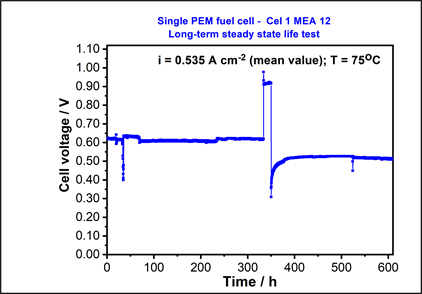
Figure 2. Single PEMFC performance (voltage vs. time) at fixed current, 75˚C, 100% RH, 1 atm, H2/O2—Test unit Cel 1 MEA 12.

Figure 3. Single PEMFC performance (voltage vs. current density) at 75˚C, 100% RH, 1 atm, H2/O2—Test unit Cel 1 MEA 11.

Figure 4. Single PEMFC performance (voltage vs. current density) at 75˚C, 100% RH, 1 atm, H2/O2—Test unit Cel 1 MEA 12.
The test with Cel 1 MEA 11 was interrupted due to time constraints and the observed fuel cell lifetime in this case was considered a censoring time. During the test with unit Cel 1 MEA 12, some non-expected interruptions had occurred and the performance degradation leaded to a failure of the fuel cell.
Figure 3 and Figure 4 correspond to the polarization curves (fuel cell voltage vs. current density) extracted during the tests with units Cel 1 MEA 11 and Cel 1 MEA 12, respectively.
The final polarization curve extracted after the conclusion of the test with Cel 1 MEA 12 showed evidence of the strong degradation of the fuel cell (Figure 4).
In general, the comparison between the initial and final polarization curves showed that, in 50% of the tests, there was a significant increase in the over potential of the electrodes after a long period of fuel cell operation in the steady-state condition, as shown in Figure 4.
The fuel cell performance loss generally corresponded to an increase in activation energy and ohmic resistance. The activation energy, which mainly comes from the electron transfer resistance at the electrode interface, is the phenomenon that governs the electrochemical process when the fuel cell is operating at low current densities. When pure hydrogen is supplied to the fuel cell, the key reaction in this range of operation is the oxygen reduction reaction (ORR) that occurs at the cathode, and that is much slower than the hydrogen oxidation reaction (HOR) that occurs at the anode. Moreover, certain operational problems, such as excessive accumulation of water in the diffusion layer of the GDE (gas diffusion electrode) or in the flow channels of the graphite plates can influence the electrochemical reactions and especially the ORR. The main causes may be a failure in water management in the membrane of the fuel cell or an inadequate configuration of the flow channels in the graphite plates. The increased ohmic losses may be related to the degradation of the polymer electrolyte membrane.
Regarding fuel cell durability assessment, all failure times (F) or censoring times (C) of the units tested under steady-state conditions were taken into consideration, as shown in Figure 5.
Initially, a non-parametric analysis was performed in order to estimate the reliability function based on the failure/censoring times shown in Figure 5. The statistical method applied to this analysis was described in [23] [24] and [25] and the Kaplan-Meier estimator was used to generate an estimate of the fuel cell reliability function. In Table 4, the Kaplan-Meier estimate of the reliability function, denoted as RKM(t), as well as the 95% confidence limits for this estimate are presented.
The following step of the failure-time (or lifetime) analysis consisted of fitting a known parametric model (exponential, Weibull, normal, log-normal or gamma) to sample data.
By using the computer program ReliaSoft Weibull++ version 6 [31] , it was found that the model that best fits the observed data was a two-parameter exponential distribution.
Besides that, it was verified that the reliability function estimates of the parametric models, for operating times smaller than 668.20 hours, are all close to the non-parametric estimation (Kaplan-Meier). For operating times greater than 668.20 hours, the most optimistic parametric model regarding the reliability of fuel cells analyzed in this study is the exponential model. The exponential model is the one that best reflects this expectation and, for this reason, was chosen to represent the lifetimes of the fuel cells. In addition, the exponential model, characterized by a constant failure rate function, is able to explain the fact that some fuel cells have presented a linear loss of performance over time, considering the period of observation of the test.
The probability density function f(t) of a random variable T (failure-time) that follows a two-parameter exponential distribution is given by Equation (1) below:
(1)
where γ is a position parameter (in hours) and 1/λ is a scale parameter (in hours), considering that f(t) ≥ 0, λ > 0 and t ≥ 0 or γ.
The maximum likelihood method was used in order to calculate the estimates of the model parameters. The parameters γ and λ were estimated at 265.80 hours and 0.0012 failures per hour, respectively. Thus, the reliability function R(t) estimated for this study is given by Equation (2) below:
(2)
R(t) is graphically represented in Figure 6. Based on the adjusted exponential model, the maximum likelihood estimate for the mean time to failure (MTTF) of the single PEMFCs was 1094.58 hours, and the 95% confidence interval for this parameter was [533.03 hours; 2836.13 hours]. The estimate for the median of the distribution was 840.27 hours, and the 95% confidence interval was [451.03 hours; 2047.42 hours].
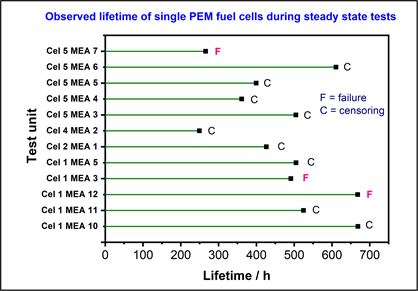
Figure 5. Failure/censoring times of single PEMFCs tested in stable conditions (fixed current, 75˚C, 100% RH, 1 atm, H2/O2).

Figure 6. Reliability function of the two-parameter exponential model adjusted for the single PEMFCs.
Table 4. Kaplan-Meier estimate for the reliability function of single PEMFCs.
The non-parametric and the parametric estimates obtained for the reliability of the fuel cells can be compared through the calculation of RKM(t) and R(t) at a specified time. For example, in Table 4, it can be observed that RKM(668.20) is 0.390. By Equation (2), the reliability of the fuel cells for a 668.2-hour mission, R(668.20), is 0.617. This result indicates that the exponential model adjusted in the analysis may be overestimating the reliability of the fuel cells tested for this study. Thus, until the sample size of failure times observed in fuel cell life tests is large enough to improve the accuracy of the estimates calculated in this analysis, the results obtained from fitting a two-parameter exponential model should be interpreted with adequate reservation.
4. Conclusions
The methodology proposed in this study included both approaches, qualitative and quantitative, for performing the reliability analysis of fuel cells. In the quantitative approach, which was the main theme of this article, the sample data generated in life tests of single PEMFCs were analyzed. Statistical methods for reliability data were applied and the following results were obtained: 1) assessment of fuel cell durability; and 2) assessment of fuel cell performance over time.
Among the main results generated from this study, it is important to mention that PEMFCs lifetime was modeled according to a two-parameter exponential distribution, and the parameters λ and γ were estimated at 265.80 hours and 0.0012 failures per hour, respectively. Thus, the mean time to failure of single PEMFCs produced at IPEN-CNEN/SP was estimated at 1094.58 hours, and [533.03 hours; 2836.13 hours] was the 95% confidence interval for this parameter. In addition, the voltage decay rate of these single PEMFCs could be represented by its median value which was calculated at 0.08 mV·h−1 (80 µV·h−1).
One of the main limitations of the research developed in this study is that the quantitative results on the performance and durability of the fuel cells obtained from the tests should be used with great caution, taking into consideration a critical evaluation of the selected devices and test conditions imposed on them. In general, experiments like the ones that were conducted in this study are affected by several factors, including, in practice, budget constraints, man-hours available for test execution, and laboratory infrastructure. On the other hand, the application of the methodology proposed in this study to the development and improvement of fuel cell components represents a great advance and offers several opportunities for future research activities. Furthermore, this methodology can be implemented as part of a reliability growth analysis of the fuel cells and can be integrated into the design process of these devices.
Finally, the laboratorial infrastructure of IPEN-CNEN/SP, which is adequately prepared for fuel cell testing, may be shared with other research institutes and universities in a partnership framework for the development of power conversion systems based on fuel cells.
Acknowledgements
Financial supports by FINEP (Financiadora de Inovação e Pesquisa) and FAPESP (Fundação de Amparo à Pesquisa do Estado de São Paulo), which are governmental organizations that stimulate scientific development in Brazil, are gratefully acknowledged. Language help was provided by Ms Debora de Lorenzo, whose contribution was of great value to the elaboration of this article.
Conflicts of Interest
The authors declare no conflicts of interest regarding the publication of this paper.
Cite this paper
Oliveira, P.S.P., Andrea, V., Santiago, E.I., Lopes, T., Andrade, D.A. and Linardi, M. (2019) A Reliability-Based Strategy for the Analysis of Single Proton Exchange Membrane Fuel Cells. Energy and Power Engineering, 11, 303-319. https://doi.org/10.4236/epe.2019.118019
References
- 1. Linardi, M. (2010) Introducao à Ciência e Tecnologia de Células a Combustível. Artliber, Sao Paulo.
- 2. Wendt, H., Linardi, M. and Aricó, E.M. (2002) Células a Combustível de Baixa Potência para Aplicacoes Estacionárias, Química Nova, 25, 470-476. https://doi.org/10.1590/S0100-40422002000300021
- 3. Nonobe, Y. (2017) Development of the Fuel Cell Vehicle Mirai. IEEJ Transactions on Electrical and Electronic Engineering, 12, 5-9. https://doi.org/10.1002/tee.22328
- 4. Lipman, T.E. (2017) Emerging Technologies for Higher Fuel Economy Automobile Standards. Annual Review of Environment and Resources, 42, 267-288. https://doi.org/10.1146/annurev-environ-110615-085844
- 5. Serov, A. and Kwak, C. (2009) Progress in Development of Direct Dimethyl Ether Fuel Cells. Applied Catalysis B: Environmental, 91, 1-10. https://doi.org/10.1016/j.apcatb.2009.06.018
- 6. Li, D., Lv, H., Kang, Y., Markovic, N.M. and Stamenkovic, V.R. (2016) Progress in the Development of Oxygen Reduction Reaction Catalysts for Low-Temperature Fuel Cells. Annual Review of Chemical and Biomolecular Engineering, 7, 509-532. https://doi.org/10.1146/annurev-chembioeng-080615-034526
- 7. US Department of Energy: Fuel Cells Technologies Office Multi-Year Research, Development, and Demonstration Plan. https://www.energy.gov/eere/fuelcells/downloads/fuel-cell-technologies-office-multi-year-research-development-and-22
- 8. Whiteley, M., Fly, A., Leigh, J., Dunnett, S. and Jackson, L. (2015) Advanced Reliability Analysis of Polymer Electrolyte Membrane Fuel Cells Using Petri-Net Analysis and Fuel Cell Modelling Techniques. International Journal of Hydrogen Energy, 40, 11550-11558. https://doi.org/10.1016/j.ijhydene.2015.01.154
- 9. Whiteley, M., Dunnett, S. and Jackson, L. (2016) Failure Mode and Effect Analysis, and Fault Tree Analysis of Polymer Electrolyte Membrane Fuel Cells. International Journal of Hydrogen Energy, 41, 1187-1202. https://doi.org/10.1016/j.ijhydene.2015.11.007
- 10. Placca, L. and Kouta, R. (2011) Fault Tree Analysis for PEM Fuel Cell Degradation Process Modelling. International Journal of Hydrogen Energy, 36, 12393-12405. https://doi.org/10.1016/j.ijhydene.2011.06.093
- 11. Ireson, W.G., Coombs, C.F. and Moss, R.Y. (1996) Handbook of Reliability Engineering and Management. 2nd Edition, McGraw Hill, New York.
- 12. McDermott, R.E., Mikulak, R.J. and Beauregard, M.R. (1996) The Basics of FMEA. Quality Resources, New York.
- 13. Freitas, M.A. and Colosimo, E.A. (1997) Confiabilidade: Análise de Tempo de Falhas e Testes de Vida Acelerados. Fundacao Christiano Ottoni, Belo Horizonte.
- 14. Fowler, M.W., Mann, R.F., Amphlett, J.C., Peppley, B.A. and Roberge, P.R. (2002) Incorporation of Voltage Degradation into a Generalised Steady State Electrochemical Model for a PEM Fuel Cell. Journal of Power Sources, 106, 274-283. https://doi.org/10.1016/S0378-7753(01)01029-1
- 15. Kundu, S., Fowler, M.W., Simon, L.C. and Grot, S. (2006) Morphological Features (Defects) in Fuel Cell Membrane Electrode Assemblies. Journal of Power Sources, 157, 650-656. https://doi.org/10.1016/j.jpowsour.2005.12.027
- 16. De Bruijn, F.A., Dam, V.A.T. and Janssen, G.J.M. (2007) Review: Durability and Degradation Issues of PEM Fuel Cell Components. Fuel Cells, 8, 3-22. https://doi.org/10.1002/fuce.200700053
- 17. Cleghorn, S.J.C., Mayfield, D.K., Moore, D.A., Moore, J.C., Rusch, G., Sherman, T.W., Sisofo, N.T. and Beuscher, U. (2006) A Polymer Electrolyte Fuel Cell Life Test: 3 Years of Continuous Operation. Journal of Power Sources, 158, 446-454. https://doi.org/10.1016/j.jpowsour.2005.09.062
- 18. Liu, D. and Case, S. (2006) Durability Study of Proton Exchange Membrane Fuel Cells Under Dynamic Testing Conditions with Cyclic Current Profile. Journal of Power Sources, 162, 521-531. https://doi.org/10.1016/j.jpowsour.2006.07.007
- 19. Schmittinger, W. and Vahidi, A. (2008) A Review of the Main Parameters Influencing Long-Term Performance and Durability of PEM Fuel Cells. Journal of Power Sources, 180, 1-14. https://doi.org/10.1016/j.jpowsour.2008.01.070
- 20. Wu, J., Yuan, X.Z., Martin, J.J., Wang, H., Zhang, J., Shen, J., Wu, S. and Merida, W. (2008) A Review of PEM Fuel Cell Durability: Degradation Mechanisms and Mitigation Strategies. Journal of Power Sources, 184, 104-119. https://doi.org/10.1016/j.jpowsour.2008.06.006
- 21. Marrony, M., Barrera, R., Quenet, S., Ginocchio, S., Montelatici, L. and Aslanides, A. (2008) Durability Study and Lifetime Prediction of Baseline Proton Exchange Membrane Fuel Cell Under Severe Operating Conditions. Journal of Power Sources, 182, 469-475. https://doi.org/10.1016/j.jpowsour.2008.02.096
- 22. Borup, R., Meyers, J., Pivovar, B., Kim, Y.S., Mukundan, R., Garland, N., Myers, D., Wilson, M., Garzon, F., Wood, D., Zelenay, P., More, K., Stroh, K., Zawodzinski, T., Boncella, J., McGrath, J.E., Inaba, M., Miyatake, K., Hori, M., Ota, K., Ogumi, Z., Miyata, S., Nishikata, A., Siroma, Z., Uchimoto, Y., Yasuda, K., Kimijima, K.I. and Iwashita, N. (2007) Scientific Aspects of Polymer Electrolyte Fuel Cell Durability and Degradation. Chemical Reviews, 107, 3904-3951. https://pubs.acs.org/doi/abs/10.1021/cr050182l https://doi.org/10.1021/cr050182l
- 23. Meeker, W.Q. and Scobar, L.A. (1998) Statistical Methods for Reliability Data. John Wiley & Sons, New York.
- 24. Nelson, W.B. (1998) Applied Life Data Analysis. John Wiley & Sons, New York.
- 25. Lawless, J.F. (2003) Statistical Models and Methods for Lifetime Data. 2nd Edition, John Wiley & Sons, New York. https://doi.org/10.1002/9781118033005
- 26. European Commission (2010) Testing the Voltage and Power as Function of Current Density: Polarisation Curve for a SOFC Single Cell. JRC Scientific and Technical Reports.
- 27. European Commission (2010) Testing the Voltage and Power as Function of Current Density Following an On/Off Profile versus Time: Accelerated Ageing On/Off Cycling Test for a PEFC Single Cell. JRC Scientific and Technical Reports.
- 28. European Commission (2010) Testing the Voltage and Power as Function of Current Density: Long Term Durability Steady Test for a Single PEFC. JRC Scientific and Technical Reports.
- 29. Malkow, T., De Marco, G., Pilenga, A., Honselaar, M., Tsotridis, G., Escribano, S., Antoni, L., Rei?ner, R., Thalau, O., Sitters, E. and Heinz, G. (2010) Testing the Humidification Sensitivity of a Single PEFC-Characterisation of the Performances of a PEFC Operating with Fuel and Oxidant at Various Relative Humidity. JRC Scientific and Technical Reports.
- 30. Andrade, A.B., Bejarano, M.L.M., Cunha, E.F., Robalinho, E. and Linardi, M. (2009) Fabrication of High Precision PEMFC Membrane Electrode Assemblies by Sieve Printing Method. Journal of Fuel Cell Science and Technology, 6, Article ID: 021305.
- 31. ReliaSoft Corporation, Weibull++ Version 6, Tucson-AZ, 1992-2000.