Energy and Power Engineering
Vol.6 No.9(2014), Article
ID:49556,13
pages
DOI:10.4236/epe.2014.69020
A High-Efficiency Single-Stage Low-Power Photovoltaic Inverter System with Maximum Power Point Tracking Control
Ching-Ming Lai1, Hsien-Peng You2*
1Department of Vehicle Engineering, National Taipei University of Technology, Taipei, Taiwan
2UPE-Power Technology Co., Ltd., Taichung, Taiwan
Email: pecmlai@gmail.com, *steven.you@upe-power.com.tw
Copyright © 2014 by authors and Scientific Research Publishing Inc.
This work is licensed under the Creative Commons Attribution International License (CC BY).
http://creativecommons.org/licenses/by/4.0/


Received 21 June 2014; revised 26 July 2014; accepted 7 August 2014
ABSTRACT
This paper proposes a single-stage inverter system with maximum power point tracking control (MPPT) applicable in low-power photovoltaic (PV) energy conversion systems. The proposed system is successfully implemented using a single digital signal processor (DSP) TMS320F2808. The proposed single-stage inverter system has the following features: 1) the ability to harvest the maximum PV power using two simple and effective current sampling methods; 2) flexible topology based on the positioning of DC link capacitor on the outside of the inverter bridge circuits; 3) reduced volume and higher efficiency than the conventional two-stage inverters, and 4) MPPT accuracy of 99.3% with overall efficiency of 90% under the full-load condition.
Keywords:PV, Single-Stage Inverter, MPPT, DSP

1. Introduction
The development of alternative energy sources has been accelerated due to the growing demand for energy, high oil prices, and environmental concerns, such as the accumulation of greenhouse gasses [1] -[4] . According to the International Energy Outlook 2009 (IEO 2009) report prepared by the Energy Information Administration of the USA [5] , total world consumption of marketed energy is projected to increase by 44% from 2006 to 2030, as shown as Figure 1. This has driven the research efforts in areas such as photovoltaic (PV) cells [6] -[10] , wind energy [11] -[14] , fuel cells [15] -[19] . Photovoltaic technology is perhaps the best known of these alternatives,

providing low-voltage DC output for small-scale distributed generation installations.
Conventional two-stage photovoltaic energy conversion systems comprise an MPPT controlling DC/DC converter followed by a DC/AC inverter. Despite the effectiveness of this approach, two-stage inverter systems tend to be exceedingly large and expensive. As shown in Figure 2, a single-stage topology could help to reduce the number of components, thereby reducing the physical size, increasing efficiency, and facilitating implementation [20] . This paper presents a low-power photovoltaic inverter system capable of converting photovoltaic energy into an AC sinusoidal output as well as tracking the maximum power point using a single-stage topology. The proposed single-stage photovoltaic inverter system uses only one digital signal processor (DSP) TMS320 F2808 to enable the perturbation and observation (P&O) MPPT strategy with unipolar sinusoidal pulse width modulation (SPWM) switching technique.
2. Equivalent Circuit Model of Photovoltaic Cell
The equivalent circuit of a photovoltaic cell can be modeled using a current source in parallel with a diode, and mathematically modeled using Equation (1). In practice, no photovoltaic cell is ideal, hence, a series resistance and shunt resistance are added to the model, which results in the equivalent circuit presented in Figure 3 [21] . The current through this non-ideal circuit is described in Equation (2).
 (1)
(1)
where VT represents the thermal voltage, n is the diode ideality factor (1 for an ideal diode), and Is represents the reverse saturation current. In addition, the number of current Iph depends on the irradiation to which the photovoltaic cell is exposed as well as environmental temperature.
 (2)
(2)
 (3)
(3)
where:
Rs: Series resistance (Ù);
Tr: Cell reference temperature (˚K);
Rp: Parallel resistance (Ù);

Figure 2. Proposed single-stage photovoltaic inverter system.

Figure 3. Equivalent circuit of a photovoltaic cell with parallel diode and parasitic resistance [21] .
EG: Band-gap energy of the semiconductor;
IPhr: Reverse saturation current at Tr;
q: Charge of an electron (1.6 ´ 10−19 C); K: Boltzmann’s constant.
A voltage drop occurs in photovoltaic cells when the semiconductor to the electrical contacts is in the range of few mille-ohms. Furthermore, the resistance values depend on the physical size of the photovoltaic cell. An increase is either series or parallel resistance results in the current-controlled portion of the I-V curve sagging toward the origin, resulting in a slight reduction in the terminal voltage V and short current. A general resistive load R is added to complete the equivalent circuit and describe the characteristic curves, thereby making it possible to determine the maximum power point under various levels of irradiation.
As shown in Figure 4, both Rs and Rp can be combined into a virtual photovoltaic resistance Rpv. The function of the photovoltaic parameters (Voc, Isc, Vmpp, and Impp) can be written as [22] :
 (4)
(4)
where Vmpp, Impp, Voc and Isc represent the voltage and current of maximum power point, open circuit voltage, and short circuit current of the photovoltaic cell, respectively.
The behavior of photovoltaic cell depends on the voltage and current under loads of various size or type. Figure 5 illustrates characteristics of a photovoltaic cell with I-V/P-V curves, presenting the MPP in which the maximum output power is generated. Furthermore, this point varies nonlinearly according to amount of irradiation to which the cell is exposed as well as the temperature of the environment.
Figure 6 and Figure 7 present the I-V and P-V curves under various atmospheric conditions, in which the amount of irradiation and the environmental temperature also affect I-V characteristics. For instance, an increase in irradiation or drop in temperature will increase the amount of power generated.
A photovoltaic module is an assembly of cells. PV modules are wired together in series or/and parallel to obtain voltage and current required for particular applications, as shown in Figure 8. The photovoltaic array converts sunlight directly into DC voltage and current.

Figure 4. Equivalent circuit of series/parallel module of photovoltaic cell.
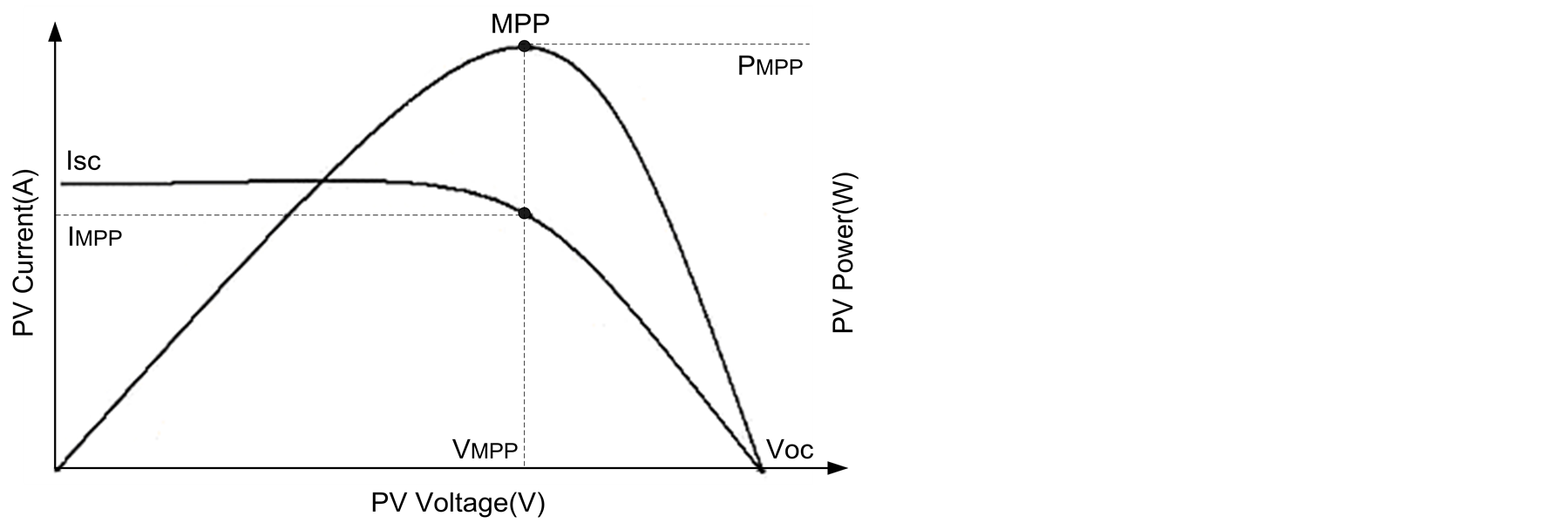
Figure 5. Characteristic curves of photovoltaic cell.
 (a)
(a) (b)
(b)
Figure 6. I-V curves with: (a) different temperature and (b) different irradiation conditions.
3. Design and Analysis of Photovoltaic Inverter System with MPPT Control
In the following, we present the hardware design and system control strategies of the single-stage MPPT inverter. The DSP-based P&O MPPT method and unipolar SPWM voltage switching techniques were adopted for the single-phase inverter in order to extract the maximum power out of the photovoltaic array and rectify the AC line voltage. The photovoltaic energy conversion system in Figure 9 comprises a PV source with DC link capacitor CDC on the DC side and a low-pass output filter on the AC side.
3.1. Single-Stage Single-Phase Full-Bridge Inverter
The structure of the single-stage full-bridge (FB) inverter includes a two-leg bridge circuit. In order to prevent short-through of the DC input, the switching operations of the upper switches are complementary with the lower switches. Protection is provided by applying a delay-time control (namely a dead-time control) between the turn-off and turn-on switches in the same leg. The four switching states are represented in Table1
 (a)
(a) (b)
(b)
Figure 7. P-V curves with (a) different temperature and (b) different irradiation conditions.

Figure 8. Series/Parallel module of solar cell.

Figure 9. Configuration of proposed single-stage single-phase photovoltaic inverter system.

Table 1. Switching states of the single-phase full-bridge inverter.
Using the same input DC voltage, the maximum output voltage of full-bridge inverter is double that of the half-bridge (HB) inverter. This means that the output current and switch currents of the full-bridge inverter are half that of an HB inverter of the same power rating. The relationship between output voltage and switching at leg A and leg B is presented in Equation (5), and the switching states of the single-phase full-bridge inverter are presented in Figure 10.
 (5)
(5)
3.2. Sinusoidal Pulse Width Modulation (SPWM) Voltage Switching Technique
SPWM is widely used in the conversion of the DC to AC for industrial applications. This approach produces a sinusoidal wave output, the amplitude and frequency of which can be controlled. Generating the switching signal involves using a sinusoidal reference signal that is compared with a repetitive switching triangular waveform. The switching frequency of the inverter is determined according to the frequency of the triangular waveform. The amplitude modulation ratio ma, and frequency modulation ratio mf are defined as follows:
 (6)
(6)
where ,
,  , f1, and fs present the peak amplitude of the sinusoidal reference signal and triangular waveform, and the frequency of the sinusoidal reference signal and triangular waveform, respectively.
In the uniploar SPWM switching scheme, the generation of a sinusoidal output voltage waveform with variable frequency and amplitude involves comparing the two sinusoidal reference signals (Vcontrol, −Vcontrol) with the triangular waveform (Vtri). The resulting PWM signals are presented in Figure 11. The resulting waveforms are used to control the switches as follows:
Leg A:
 (7)
(7)
 (8)
(8)
Leg B:
 (9)
(9)
 (10)
(10)
The output voltage with the unipolar SPWM voltage switching scheme changes according to VDC to −VDC input voltage levels. Furthermore, the frequency of the output voltage is double that of the triangular waveform, due to the control signals used for the two legs. Using uniploar SPWM voltage switching results in a smaller ripple in the current on the DC side of the inverter with the result that the switching frequency in the harmonic spectrum of the output voltage waveform is doubled, such that the lower harmonics appearing in the side band are twice the switching frequency. The output voltage depends on the amplitude modulation ratio, as follows:
 (11)
(11)
 (12)
(12)

Figure 10. Equivalent circuits correspond to the four switching states.
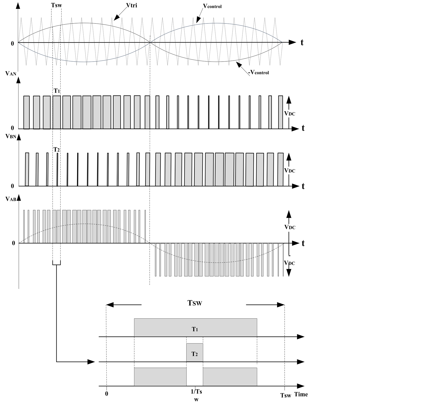
Figure 11. Adopted unipolar SPWM voltage switching technique.
In addition, the harmonic order h can be presented as:
 (13)
(13)
where the harmonics exist as sidebands around the multiples of 2mf, as shown in Figure 12, in which h is odd, such that k obtains only odd values.
4. Proposed Current Sensing Technique and Control Flow-Chart
A conventional single-stage MPPT inverter is presented in Figure 13(a). To decrease the input voltage ripple of the inverter, the DC side of the inverter is normally connected to a large capacitor. This paper proposes an alternative current sensing technique to enable maximum power point tracking inverter, as shown in Figure 13(b). The internal DC link capacitor on the DC side can be moved outside the inverter to enhance system flexibility, while retaining the accuracy of MPPT within a conventional topology. We also propose a new control strategy to enable the PWM interruption of upper-switch (TA+) for analog to digital (A/D) channel conversion, when the event time-based counter increments off the lower-switch (TA−). This makes it possible to prevent the extraction of switching spikes when the A/D converter is activated and also provides a number of additional options for sampling by controlling the dead-time. The control flow-chart of the proposed inverter system is presented in Figure 14.
5. Experimental Results of Proposed Low-Power Photovoltaic Inverter System
This study fabricated a laboratory prototype to validate the accuracy and efficiency of the proposed low-power photovoltaic conversion system. The test conditions of the experiments are presented in Table2 The bench setup in the experiment comprises a full-bridge inverter with a passive filter and a solar array simulator (Agilent E4360) as a power source, delivering the maximum output power as determined by the electrical characteristics of the photovoltaic cell array.
5.1. Experiment-1 (Conventional MPPT Inverter System)
This section presents the implementation of a conventional energy inverter system, in which the sensing waveforms Ipv and Vpv are the DC level. We began by setting the initial amplitude modulation ratio as 0.6, such that the steady-state MPPT performance can be obtained following the activation of the system. The maximum power for the available atmospheric conditions was set to approximately 11W with MPP current and voltage of Impp = 1.1 A and Vmpp = 10 V, respectively. Figure 15 shows that the solar array simulator can deliver an output power of approximately 10.86 W to the inverter, thereby achieving 98.8% accuracy. The experimental waveform obtained for a supplied power of 50 W is presented in Figure 16.
5.2. Experiment-2 (Proposed MPPT Inverter System)
For this experimentation, Figure 17 and Figure 18 present the input and output parameters (Vpv, Ipv, Ppv, Iout, Vout, THD) for a supplied power of 10 W and 50 W, respectively. The spike of voltage and current in Figure 17(b) and Figure 18(b) were generated primarily through tracking variations.

Figure 12. Analysis of harmonics in unipolar SPWM voltage switching technique (ma = 0.8).
Table 2. Specifications of the experimental prototype system.
 (a)
(a)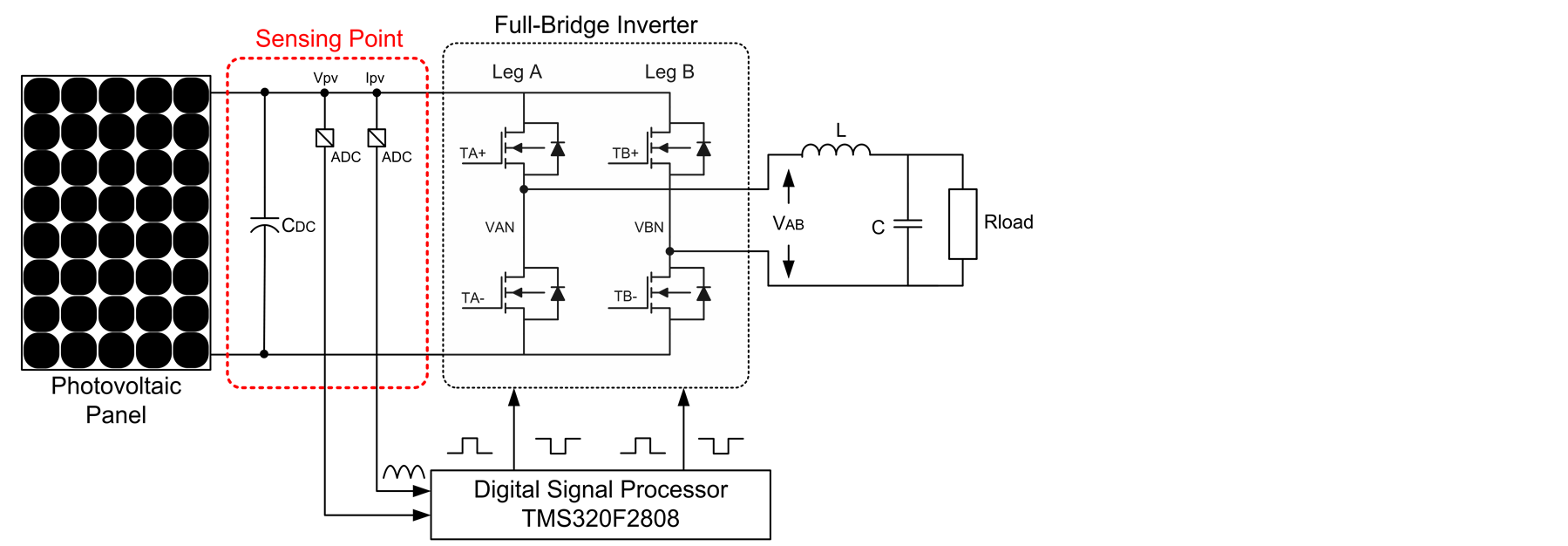 (b)
(b)
Figure 13. Current sensing techniques for single-stage inverter: (a) conventional and (b) proposed.
5.3. MPPT Accuracy and Overall Efficiency
Overall efficiency depends on the efficiency of the inverter and the MPPT algorithm used to extracts the maximum power from the PV module. The overall efficiency of the photovoltaic system is defined by Equation (14). As shown in Figure 19 and Figure 20, the proposed energy conversion system achieved the MPPT accuracy
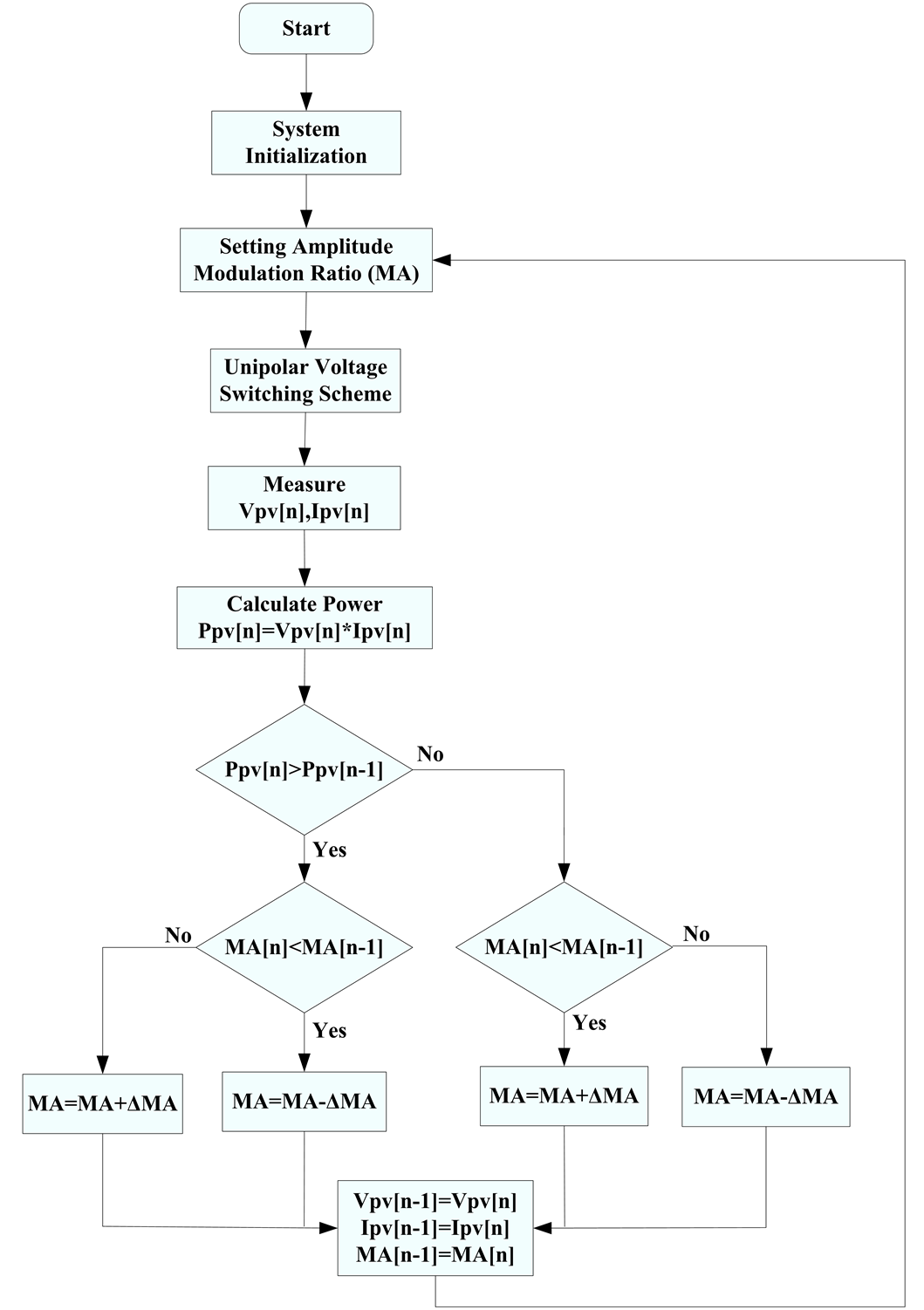
Figure 14. Proposed control flow-chart.

Figure 15. Conventional MPPT inverter with 10 W power.
and overall efficiency values of 99.3% and 90% under the full-load condition, respectively.
 (14)
(14)

Figure 16. Conventional MPPT inverter with 50 W power.
 (a)
(a) (b)
(b)
Figure 17. Proposed MPPT inverter with 10 W power.
 (a)
(a) (b)
(b)
Figure 18. Proposed MPPT inverter with 50 W power.

Figure 19. MPPT accuracy of conventional and proposed topologies.

Figure 20. Overall efficiency of conventional and proposed topologies.
6. Conclusions
This paper proposes a single-stage maximum power point tracking inverter for low-power photovoltaic energy conversion systems. The proposed scheme is successfully implemented using a DSP TMS320F2808, the results lead to the following conclusions: 1) The performance of the single-stage MPPT inverter is validated using a 50W prototype. Two different current sampling methods can be applied to maximize power generation. The proposed topology enhances the flexibility of the system by moving the internal DC link capacitor to the outside of the inverter; 2) A single-stage energy conversion system results in a smaller physical volume with higher efficiency, compared to conventional two-stage designs; 3) The MPPT accuracy and overall efficiency of the proposed energy conversion system are 99.3% and 90% under full-load condition, showing a marked increase over the 98.5% accuracy and 89.5% efficiency obtained using a conventional topology.
Acknowledgements
This study was supported by the Ministry of Science and Technology (formerly National Science Council), Taiwan, R.O.C. under Grant NSC 102-2218-E-033-004.
References
- Bull, S.R. (2001) Renewable Energy Today and Tomorrow. Proceedings of the IEEE, 89, 1216-1226. http://dx.doi.org/10.1109/5.940290
- Bose, B.K. (2010) Global Warming: Energy, Environment Pollution, and the Impact of Power Electronics. IEEE Industrial Electronics Magazine, 4, 6-17. http://dx.doi.org/10.1109/MIE.2010.935860
- Guerrero, J.M., Blaabjerg, F., Zhelev, T., Hemmes, K., Monmasson, E., Jemei, S., Comech, M.P., Granadino, R. and Frau, J.I. (2010) Distributed Generation: Toward a New Energy Paradigm. IEEE Industrial Electronics Magazine, 4, 52-64. http://dx.doi.org/10.1109/MIE.2010.935862
- Liserre, M., Sauter, T. and Hung, J.-Y. (2010) Future Energy Systems: Integrating Renewable Energy Sources into the Smart Power Grid through Industrial Electronics. IEEE Industrial Electronics Magazine, 4, 18-37. http://dx.doi.org/10.1109/MIE.2010.935861
- USA Department of Energy (2009) International Energy Outlook. http://www.eia.doe.gov
- Wai, R.-J., Wang, W.-H. and Lin, C.-Y. (2008) High-Performance Stand-Alone Photovoltaic Generation System. IEEE Transactions on Industrial Electronics, 55, 240-250. http://dx.doi.org/10.1109/TIE.2007.896049
- Bialasiewicz, J.T. (2008) Renewable Energy Systems with Photovoltaic Power Generators: Operation and Modeling. IEEE Transactions on Industrial Electronics, 55, 2752-2758. http://dx.doi.org/10.1109/TIE.2008.920583
- Lai, C.-M. and Liao, Y.-H. (2011) A Single-Stage PV Module Integrated Converter (MIC) with High Voltage Gain Capability. International Review of Electrical Engineering, 6, 587-592.
- Shen, C.-L. and Tsai, C.-T. (2012) Double-Linear Approximation Algorithm to Achieve Maximum-Power-Point Tracking for PV Arrays. Energies, 5, 1982-1997. http://dx.doi.org/10.3390/en5061982
- Chao, K.-H., Yang, M.-S. and Hung C.-P. (2013) Islanding Detection Method of a Photovoltaic Power Generation System Based on a Cerebellar Model Articulation Controller Neural Network. Energies, 6, 4152-4169. http://dx.doi.org/10.3390/en6084152
- Li, H. and Chen, Z. (2008) Overview of Different Wind Generator Systems and Their Comparisons. IET Renewable Power Generation, 2, 123-138.
- Zhu, Y., Cheng, M., Hua, W. and Wang, W. (2012) A Novel Maximum Power Point Tracking Control for Permanent Magnet Direct Drive Wind Energy Conversion Systems. Energies, 5, 1398-1412. http://dx.doi.org/10.3390/en5051398
- Tsai, C.-T. (2012) Energy Storage System with Voltage Equalization Strategy for Wind Energy Conversion. Energies, 5, 2331-2350. http://dx.doi.org/10.3390/en5072331
- Huang, S.-C., Lo, S.-L. and Lin, Y.-C. (2013) To Re-Explore the Causality between Barriers to Renewable Energy Development: A Case Study of Wind Energy. Energies, 6, 4465-4488. http://dx.doi.org/10.3390/en6094465
- Yu, X., Starke, M.R., Tolbert, L.M. and Ozpineci, B. (2007) Fuel Cell Power Conditioning for Electric Power Applications: A Summary. IET Electric Power Applications, 1, 643-656.
- Pan, C.-T. and Lai, C.-M. (2010) A High Efficiency High Step-Up Converter with Low Switch Voltage Stress for Fuel Cell System Applications. IEEE Transactions on Industrial Electronics, 57, 1998-2006. http://dx.doi.org/10.1109/TIE.2009.2024100
- Zhai, Q., Cao, H., Zhao, X. and Yuan, C. (2011) Cost Benefit Analysis of Using Clean Energy Supplies to Reduce Greenhouse Gas Emissions of Global Automotive Manufacturing. Energies, 4, 1478-1494. http://dx.doi.org/10.3390/en4101478
- Arango, E., Ramos-Paja, C.A., Calvente, J., Giral, R. and Serna, S. (2012) Asymmetrical Interleaved DC/DC Switching Converters for Photovoltaic and Fuel Cell Applications—Part 1: Circuit Generation, Analysis and Design. Energies, 5, 4590-4623. http://dx.doi.org/10.3390/en5114590
- Arango, E., Ramos-Paja, C.A., Calvente, J., Giral, R. and Serna-Garces, S.I. (2013) Asymmetrical Interleaved DC/DC Switching Converters for Photovoltaic and Fuel Cell Applications—Part 2: Control-Oriented Models. Energies, 6, 5570-5596. http://dx.doi.org/10.3390/en6105570
- Wu, T.-F., Chang, C.-H., Lin, L.-C. and Kuo, C.-L. (2011) Power Loss Comparison of Single-and Two-Stage Grid-Connected Photovoltaic Systems. IEEE Transactions on Energy Conversation, 26, 707-715. http://dx.doi.org/10.1109/TEC.2011.2123897
- Komp, R.J. (1995) Practical Photovoltaics: Electricity from Solar Cells. 3rd Edition, Aatec Publications, Ann Arbor.
- Esram, T. and Chapman, P.L. (2007) Comparison of Photovoltaic Array Maximum Power Point Tracking Techniques. IEEE Transactions on Energy Conversation, 22, 439-449. http://dx.doi.org/10.1109/TEC.2006.874230
NOTES

*Corresponding author.