Energy and Power Engineering
Vol. 5 No. 2A (2013) , Article ID: 30599 , 7 pages DOI:10.4236/epe.2013.52A002
Analysis of Thermodynamic Characteristic Changes in Direct Expansion Ground Source Heat Pump Using Hydrofluoroolefins (HFOs) Substituting for HFC-134a
1School of Energy, Power & Mechanical Engineering, North China Electric Power University, Baoding, China
2Swan Center for Energy Research, Newcastle University, Newcastle Upon Tyne, UK
Email: gaoyuefen@gmail.com, tony.roskilly@ncl.ac.uk;
Copyright © 2013 Yuefen Gao et al. This is an open access article distributed under the Creative Commons Attribution License, which permits unrestricted use, distribution, and reproduction in any medium, provided the original work is properly cited.
Received February 28, 2013; revised March 27, 2013; accepted April 12, 2013
Keywords: Direct Expansion Ground Source Heat Pump (DXGSHP); Thermodynamic Performance; HFO-1234yf; HFO-1234ze[E]; HFC-134a
ABSTRACT
HFO-1234yf and HFO-1234ze[E] have low global warming potential and zero ozone depletion potential. If they are used in the direct expansion ground source heat pump system substituting for HFC-134a, the system will be beneficial to mitigating climate change. This study aims to find out the thermodynamic characteristics of the direct expansion ground source heat pump system using HFO-1234yf or HFO-1234ze[E] by theoretical calculation. The results indicate that HFO-1234yf system in an actual cycle has the highest COP. HFO-1234yf and HFO-1234ze[E] have such smaller capacity per unit of swept volume that they need larger compression capacity if providing the same heating or cooling loads. For a given unit when HFC-134a is replaced with HFO-1234yf or HFO-1234ze[E], the capacity will decrease. More refrigerant charge is required in the HFO-1234yf or HFO-1234ze[E] system. The results also present that more refrigerant charge is required in the cooling mode than in the heating mode.
1. Introduction
Direct expansion ground source heat pump (DXGSHP) has only copper loops circulating refrigerants which exchanges heat directly with the soil through the walls of the copper tubing. It is an energy-efficient and environmentally clean space conditioning system. However, it has the risk of ground contamination if refrigerant leak into the ground, as the loops containing refrigerant are directly buried in the ground.
One of the solutions to this problem is to select non-toxic, environment-amiable working fluids. Generally, commercial and residential heat pump systems use hydrofluorocarbons (HFCs) or their mixtures as refrigerants. HFCs have zero ozone depletion potential (ODP), but most of them have relatively high values of global warming potentials (GWP). In developed countries, refrigerants with high GWP are facing to be phased out. The European Union’s F-gas regulation and the directive 2006/40/EC ban fluorinated gases having GWP greater than 150 in new mobile models from January 1, 2011 and in new vehicles from January 1, 2017 [1,2]. More efforts have been underway to investigate fluorinated propene isomers as possible refrigerants. In 2007, DuPont and Honeywell co-developed hydrofluoroolefins (HFOs) to replace HFCs in air conditioning units. HFOs are a class of compounds. Among the compounds, HFO-1234yf and HFO-1234ze[E] are the two most suitable to the air conditioning system [3].
HFO-1234yf and HFO-1234ze[E] possess the similar thermodynamic behavior to HFC-134a. They have a 100 year GWP of 4 and 6 respectively. Both of them are being considered as a possible replacement for HFC-134a which has a high GWP value of 1430 [3]. The US EPA has released a proposed rule for HFO-1234yf as an automotive refrigerant [4].
Not only are HFOs able to be used to the air conditioning system in vehicles, they are also feasible to replace HFC-134a in commercial and residential heat pump system. Many investigations released that HFO-1234yf and HFO-1234ze[E] almost have non-toxic and environmental impact [3,5-10]. They are also compatible with the lubricate oil and materials normally used in HFC-134a system [5,11]. HFO-1234ze[E] is non-flammable, while HFO-1234yf is quite mildly flammable [3]. So they are ideal options for DXGSHP in terms of climate change and safety.
Some research results also indicated that HFOs’ thermophysical property parameters are to some extent different from HFC-134a’s [3,5,12-15]. Correspondingly, the DXGSHP system possibly has different thermodynamic performance with these refrigerants.
This study aims to compare the thermodynamic performances of the DXGSHP system using the three kinds of refrigerants and to recommend the suitable alternative substance for HFC-134a based on theoretical calculation and analysis.
2. DXGSHP System Description
In the DXGSHP system, the refrigerant loops are directly buried underground and exchange heat with the ground.
Without using an intermediate fluid, the DXGSHP system is significantly more efficient than the conventional GSHP system. Above all, the phase change of the refrigerant occurs in the ground, where latent heat is efficiently rejected or absorbed. The elimination of the water pump and the water heat exchanger also greatly reduce electricity consumption and heat losses.
Figure 1 shows a schematic diagram of DXGSHP system. The system operates in both heating and cooling mode. A reversal valve transforms the operating mode.
In the heating mode, refrigerant absorbs heat from the ground through the loops named ground heat exchanger (GHX). It then enters the compressor where it is compressed to high-temperature vapor. The discharged vapor then enters air heat exchanger (AHX) where it releases heat to the space and condenses to liquid. The liquid exits from the AHX and is throttled via the expansion valve (EV). It then enters the GHX.
In the cooling mode, inversely, the refrigerant releases heat to the ground via GHX. The refrigerant absorbs heat from the space via AHX. It then enters the compressor and is compressed. The discharged vapor enters GHX and condenses to liquid. The liquid exits from the GHX and is throttled via the EV, and finally enters the AHX.
The thermodynamic cycle is expressed in the p-h diagram (Figure 2). Both the modes have the same cycle diagram except for the parameters.
3. Simulating Calculation of the Thermodynamic Performance of DXGSHP
In order to compare the thermodynamic performance of the DX-GSHP using the three different kinds of refrigerants, simulating calculation are conducted based on the following conditions and assumptions. In the thermodynamic calculations, the thermophysical property parame-
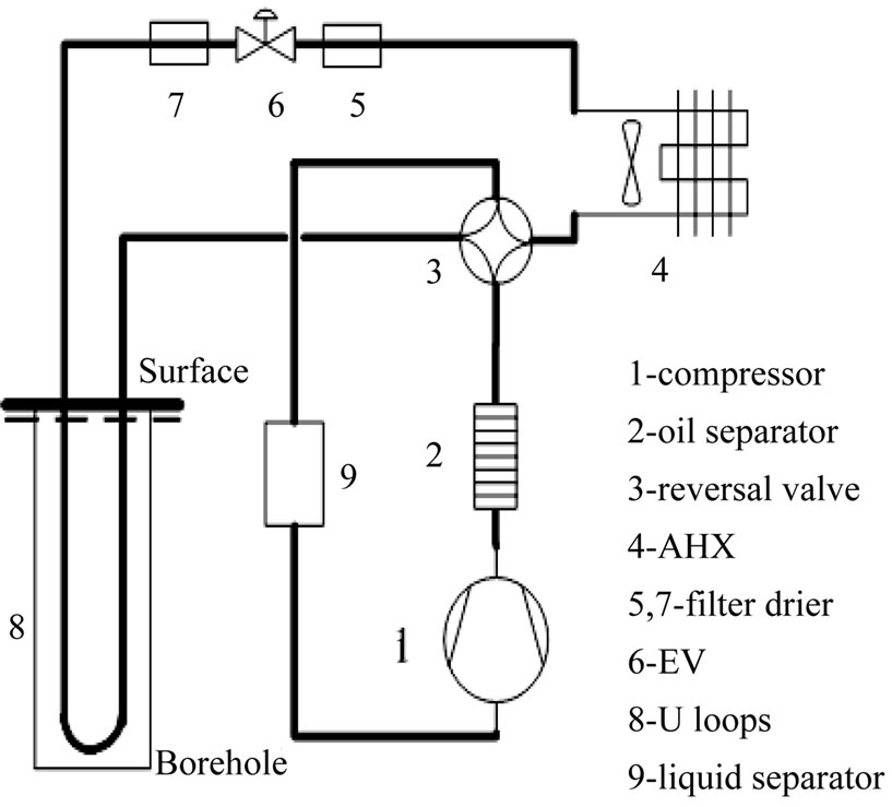
Figure 1.The schematic of the DX-GCHP system.
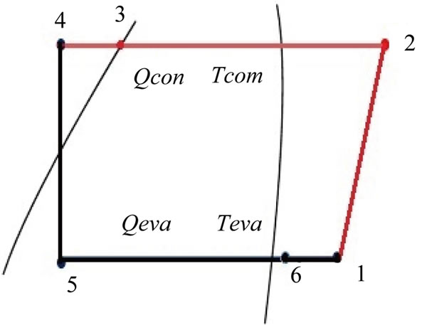
Figure 2. The p-h diagram of thermodynamic cycle.
ters of each state point are based on the program REF PROP8.0 for HFC-134a, Extended Corresponding States (ECS) model for HFO-1234ze(E) [16] and Martin-Hou Equation of State (EOS) for HFO-1234yf [5]. The ECS model has adequate accuracy [16,17].
3.1. Parameters at Design Conditions
Evaporating temperature and condensing temperature are the two most important parameters in the system design. The temperatures depend much on the external parameters. According to ANSI-AHRI870-2005, in the cooling mode, air temperature entering indoor AHX is 26.7˚C dry-bulb, 19.4˚C wet-bulb. Refrigerant temperature of liquid line from GHX is 25.0˚C. In the heating mode, air temperature entering AHX is 21.1˚C dry-bulb, 15.6˚C wet-bulb. Refrigerant temperature of vapor line from GHX is 0˚C [18]. The values of evaporating temperature and condensing temperature are presented in Table 1.
• 3.2. Assumptions in the Thermodynamic Calculation
• All the processes are under steady state conditions.
• There are no potential or kinetic energy effects and no chemical or nuclear reactions.
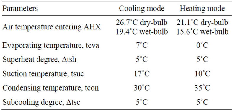
Table 1. Parameters at design conditions.
• Heat losses and refrigerant pressure drops in the connecting tubes are negligible.
• The isentropic efficiency of the compressor is 85%. The compressor mechanical efficiency and the compressor motor electrical efficiency are 70% and 75%, respectively.
• The systems with different refrigerants have the same compressing speed.
3.3. Models Assessing the Thermodynamic Performance of DXGSHP System
The performance of the system is evaluated primarily in terms of the capacity and coefficient of performance (COP). The parameters are calculated according to the steady flow energy equations.
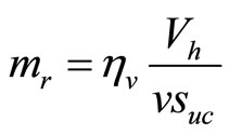
The capacity is related to the operation parameters and the refrigerant mass flow rate. The relations are expressed as
 (1)
(1)
 (2)
(2)
 (3)
(3)
 (4)
(4)
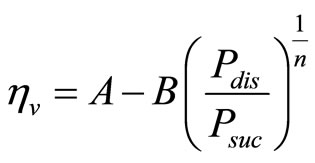
where, ηv is the volumetric efficiency, A and B are the coefficients related to the types of the compressor, n is the Specific heat ratio related to the refrigerant type.
The power input is related to the operation parameters, the mass flow rate, the mechanical efficiency of the compressor and the electrical efficiency of the driving motor.
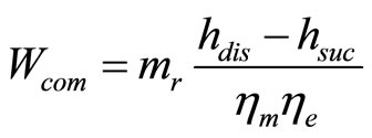 (5)
(5)
ηm tends to decrease with the increase of pressure ratio.
In the heating mode COPh is the ratio of the heating capacity Qcon to the power input Wcom, whereas, in the cooling mode COPc is the ratio of the cooling capacity Qeva,m to the power input Wcom, as given below respectively.
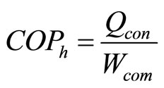 (6)
(6)
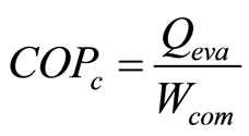 (7)
(7)
Combining the equations of (1), (5), (7) and (2), (5), (6), COPh and COPc can be expressed as
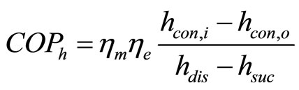 (8)
(8)
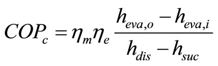 (9)
(9)
4. Results and Analysis
4.1. Calculating Results
Based on the parameters in Table 1 and the assumptions above, the calculating results are shown in Tables 2-4.
Table 2 states the typical characteristic parameters and performance values. In the theoretical cycle, HFC-134a has the highest capacity per unit mass flow rate. HFO-1234ze[E] has the closest values to HFC-134a. However, HFO-1234yf consumes the lowest power among them. The ratio of COPth,h of the three kinds of refrigerants (HCF-134a, HFO-1234yf, HFO-1234ze[E]) is 1:0.995: 1.041, while the ratio of COPth,c of the three kinds of refrigerants is 1:1.085:1.141. That means HFO-1234ze[E] has the best thermodynamic performance both in the heating mode and in the cooling mode, while HFO- 1234yf has the lowest performance in the heating mode. But, in the actual cycle, the ratio of COPh of the three kinds of refrigerants (HCF-134a, HFO-1234yf, HFO-1234ze[E]) is 1:1.028:0.955, while the ratio of COPc is 1:1.121:1.008. HFO-1234yf has the best thermodynamic performance.
Table 3 shows the calculating values and the ratios under the conditions that all refrigerants have the same cooling capacity and the mass flow rate of each refrigerant itself keeps the same in each operating mode. The system using HFO-1234yf needs 23% more mass charge than the system using HFC-134a, while the mass charge of the system using HFO-1234ze[E] is nearly 10% more than that of the system using HFC-134a. Under the same condition, the volume flow rate of HFO-1234ze[E] system is 24% - 26% more than that of HFC-134a system.
Table 4 gives the results that all refrigerants have the same volume flow rate in each operating mode. Refrigerant charge is apt for the maximum in each operating mode. The mass flow rate is regulated according to the operating mode. A reservoir is installed to contain the
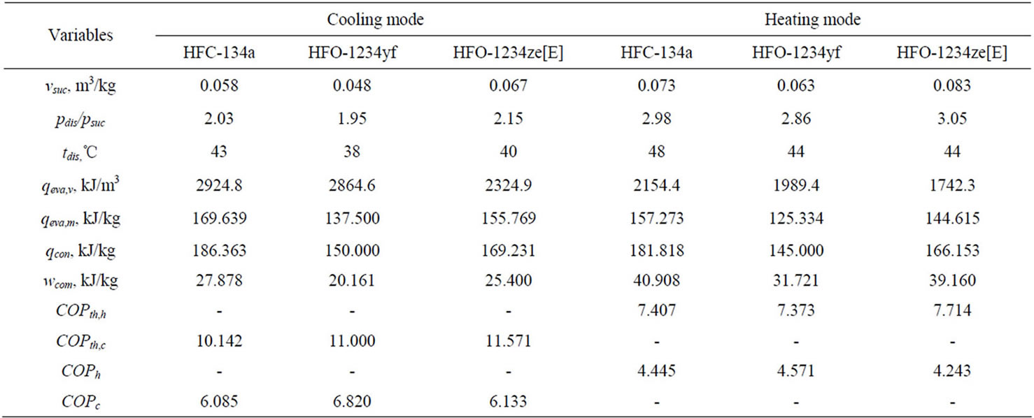
Table 2. Thermodynamic parameters.
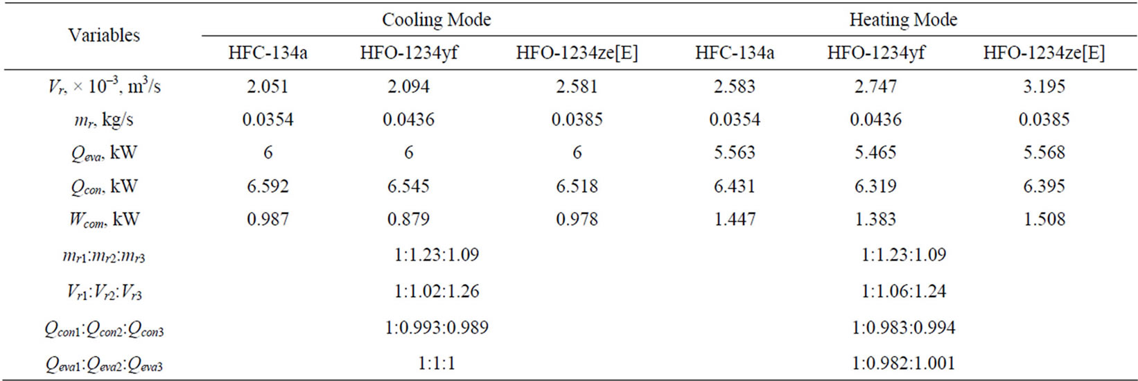
Table 3. Thermodynamic variables based on the same cooling capacity.
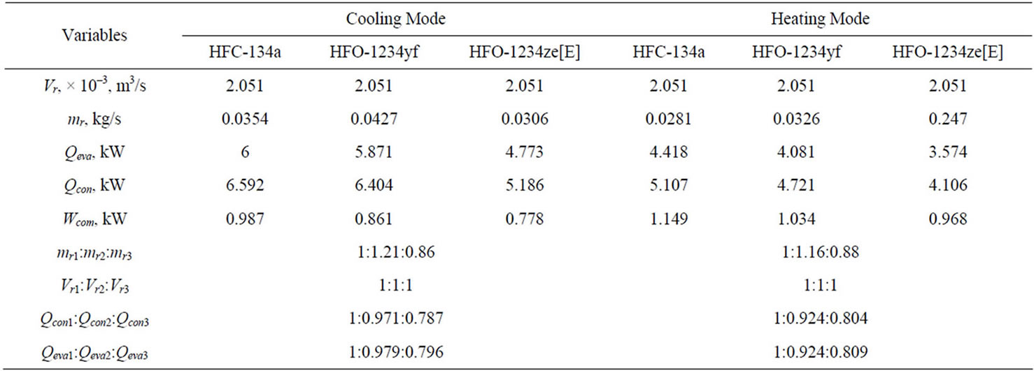
Table 4.Thermodynamic variables with the same volume flow rate.
redundant refrigerant. The results show that refrigerant charge of HFO-1234yf system is 21% more than that of HFC-134a system, whereas cooling capacity and heating capacity of HFO-1234yf system are 2% and 8% less than those of HFC-134a system respectively. As for HFO-1234ze[E] system, refrigerant charge of the system is 14% less than that of HFC-134a system, whereas heating capacity and cooling capacity of HFO-1234ze[E] system are about 20% less than those of HFC-134a system.
4.2. Analyses and Discussions
4.2.1. Thermophysical Properties
1) Pressure ratio As for the refrigerating cycle, the ratio of the discharge pressure pdis to the suction pressure psuc affects the thermodynamic performance significantly. Equations (1)-(9) show that the volumetric efficiency ηv, the mass flow rate mr, the cooling capacity Qeva or heating capacity Qcon, the power consumption Wcom and COP are the functions of the pressure ratio. The adiabatic indicated efficiency and the friction efficiency decline as the pressure ratio increases.
HFO-1234ze[E] has the highest pressure ratio (pdis/psuc), while HFO-1234yf has the lowest. In Table 2, pdis/psuc of HFO-1234ze[E] and HFO-1234yf are 2.15 and 1.95 respectively in the cooling mode, 3.05 and 2.86 in the heating mode. So, the higher pressure ratio of HFO-1234ze[E] in an actual cycle offsets its original advantages. The ratio of COPh of the three kinds of refrigerants (HCF-134a, HFO-1234yf, HFO-1234ze[E]) is 1:1.028:0.955, while the ratio of COPc is 1:1.121:1.008. As discussed above, in the theoretical cycle, HFO-1234ze[E] has the highest value of COP both in the cooling and heating mode. However, in the actual cycle HFO-1234yf obviously has the best thermodynamic performance because of its lower pressure ratio.
2) Working pressure and temperature When the systems are running under the same conditions, the suction pressure and the discharge pressure of HFO-1234yf are slightly higher than those of HCF-134a. However, HFO-1234ze[E] is just the reverse. The discharge vapor temperature of both HFO-1234yf and HFO-1234ze[E] is lower than HCF-134a. So when HFO-1234yf or HFO-1234ze[E] directly substitutes for HFC-134a, the compressor or the system still works in safety, as the maximum working pressure and temperature are kept below or close to the values of the HFC-134a system.
3) Suction specific volume vsuc
Suction specific volume vsuc affects the volume flow, and further the size of the compression chamber, evaporator, condenser and pipes.
HFO-1234ze[E] has the largest specific volumes (0.067 m3 /kg in the cooling mode, 0.083 m3/kg in the heating mode), while HFO-1234yf has the smallest ones (0.048 m3/kg in the cooling mode, 0.063 m3/kg in the heating mode). So, the capacity per unit of swept volume in the HFO-1234ze[E] system is the smallest. Larger size compression chamber, evaporator, condenser and pipes are needed. This will raise the initial investment.
4.2.2. Refrigerant Charge
1) Refrigerant mass charge varying in different systems Two cases are discussed here. The first case is that the three systems provide the same cooling capacity. The second case is that the volume flow rates in the systems keep at a given value.
In the first case, more refrigerant charge is required in the HFO-1234yf and HFO-1234ze[E] systems when they provide the same cooling capacity. The data in Table 3 show that the system using HFO-1234yf needs 23% more mass charge than the system using HFC-134a, while the mass charge of the system using HFO-1234ze[E] is nearly 10% more than that of the system using HFC-134a.
According to the results in Table 3, the volume flow rate of HFO-1234ze[E] system is 24-26% more than that of HFC-134a system. So the compression chamber and the pipes of HFO-1234ze[E] system should have larger sizes. The capacities of condenser in the heating mode (i.e., the heating capacities) of HFO-1234yf and HFO-1234ze[E] system are 2% and 1% less than that of HFC-134a system respectively.
In the second case, when HFC-134a is replaced with HFO-1234yf or HFO-1234ze[E] in a given unit, the heating capacity and the cooling capacity will decrease.
The results in Table 4 show that refrigerant charge of HFO-1234yf system is 21% more than that of HFC-134a system, whereas cooling capacity and heating capacity of HFO-1234yf system are 2% and 8% less than those of HFC-134a system respectively. As for HFO-1234ze[E] system, refrigerant charge of the system is 14% less than that of HFC-134a system, whereas heating capacity and cooling capacity of HFO-1234ze[E] system are about 20% less than those of HFC-134a system.
2) More refrigerant charge required in the cooling mode.
More refrigerant charge is required in the cooling mode than in the heating mode.
The results in Table 4 show that 24% - 31% more refrigerant charge is required in the cooling mode than in the heating mode.
4.2.3. Compression Chamber Volume
HFO-1234yf and HFO-1234ze[E] need larger compression chamber volume if they provide the same heating or cooling loads, because HFO-1234yf and HFO-1234ze[E] have the smaller capacity per unit of swept volume qeva,v than HFC-134a. According to Table 2, qeva,v of HFC-134a, HFO-1234yf and HFO-1234ze[E] systems are 2924.8 kJ/m3, 2864.6 kJ/m3, 2324.9 kJ/m3 respectively in the cooling mode, and 2154.4 kJ/m3, 1989.4 kJ/m3, 1742.3 kJ/m3 in the heating mode.
4.2.4. Capacity and COP
Capacity and COP characterize the capability and performance of the system.
As for the cooling or heating capacity, HFC-134a system has the largest capacity per unit of swept volume qeva,v. HFO-1234yf system has the similar value to HFC-134a system. But the capacity of HFO-1234ze[E] system is about 20% less than that of HFC-134a system. That means HFO-1234yf is the better replacement for HFC-134a than HFO-1234ze[E].
In terms of COP, HFO-1234yf has the better performance than the other two in the actual cycle, as discussed above.
5. Conclusions
In the DXGSHP system, the refrigerant loops are directly buried in the ground, which is in risk of ground contamination. Using non-toxic refrigerants is one effective way to solve this problem. Both HFO-1234yf and HFO-1234ze[E] are ideal potential substituent for HFC-134a in terms of climate change and safety.
HFO-1234ze[E] has the best thermodynamic performance assumed that all the refrigerants have the same mass flow rate. However, in an actual cycle HFO-1234yf has the best thermodynamic performance due to its low pressure ratio.
More refrigerant mass charges are required in the HFO-1234yf and HFO-1234ze[E] system when keeping the heating capacity the same. Moreover, more refrigerant mass charge is required in the cooling mode than in the heating mode.
HFO-1234yf and HFO-1234ze[E] have so smaller capacity per unit of swept volume that they need larger chamber if providing the same heating or cooling loads. For a given unit when HFC-134a is replaced with HFO-1234yf or HFO-1234ze[E], the capacity will decrease.
In conclusion, HFO-1234yf is the better potential alternative substance for HFC-134a. HFO-1234ze[E] can also substitute for HFC-134a, but it needs larger size unit.
6. Acknowledgements
Yuefen Gao, Honglei Zhao and Yingxin Peng are grateful to the financial support by the Fundamental Research Funds for the Central Universities (Project No: 11MG43). This work is also partly supported by European Regional Development Fund (ERDF 2009-12).
REFERENCES
- The European Parliament and the Council of the European Union, “Regulations (EC) No 842/2006 of the European Parliament and of the Council of 17 May 2006 on Certain Fluorinated Greenhouse Gases,” Official Journal of the European Union, 2006. http://eur-lex.europa.eu/LexUriServ/LexUriServ.do?uri=OJ:L:2006:161:0001:0011:EN:PDF
- The European Parliament and the Council of the European Union, “Directive 2006/40/EC of the European Parliament and of the Council of 17 May 2006 Relating to Emissions from Air-Conditioning Systems in Motor Vehicles and Amending Council Directive 70/156/EEC,” Official Journal of the European Union, 2006. http://eur-lex.europa.eu/LexUriServ/LexUriServ.do?uri=OJ:L:2006:161:0012:0018:EN:PDF
- T. G. A. Vink, “Synthetic and Natural Refrigeration Fluids Recent Developments,” 2012. http://www.fluorocarbons.org/uploads/Modules/Library/tvink_honeywell_ecocool10.pdf
- USEPA, “Protection of Stratospheric Ozone: New Substitute in the Motor Vehicle Air Conditioning Sector Under the Significant New Alternatives Policy (SNAP) Program,” Federal Register, Vol. 74, No. 200, 2009. http://www.gpo.gov/fdsys/pkg/FR-2009-10-19/pdf/E9-25106.pdf
- T. J. Leck, “Evaluation of HFO-1234yf as a Potential Replacement for R-134a in Refrigeration Applications,” Third IIR Conference on Thermophysical Properties and Transfer Processes of Refrigerants, Boulder, 23-26 June 2009. http://www2.dupont.com/Refrigerants/en.../HFO-1234yf_IIR_Leck.pdf
- C. Zilio, J. S. Brown, G. Schiochet and A. Cavallini, “The Refrigerant R1234yf in Air Conditioning Systems,” Energy, 36, No. 10, 2011, pp. 6110-6120. doi:10.1016/j.energy.2011.08.002
- P. Schuster, R. Bertermann, G. M. Rusch and W. Dekant, “Biotransformation of trans-1,1,1,3-tetrafluoropropene (HFO-1234ze),” Toxicology and Applied Pharmacology Vol. 239, No. 3, 2009, pp. 215-223. doi:10.1016/j.taap.2009.06.018
- P. Schuster, R. Bertermann, T. A. Snow, X. Han, G. M. Rusch and G. W. Jepson, “Biotransformation of 2,3,3,3- tetrafluoropropene (HFO-1234yf),” Toxicology and Applied Pharmacology, Vol. 233, No. 3, 2008, pp. 323-332. doi:10.1016/j.taap.2008.08.018
- T. J. Wallington, M. P. S. Andersen and O. J. Nielsen, “Estimated Photochemical Ozone Creation Potentials (POCPs) of CF3CFCH2 (HFO-1234yf) and Related Hydrofluoroolefins (HFOs),” Atmospheric Environment, Vol. 44, No. 11, 2010, pp. 1478-1481. doi:10.1016/j.atmosenv.2010.01.040
- K. Takizawa, K. Tokuhashi and S. Kondo, “Flammability Assessment of CH2CFCF3: Comparison with Fluoroalkenes and Fluoroalkanes,” Journal of Hazardous Materials, Vol. 172, No. 2-3, 2009, pp. 1329-1338. doi:10.1016/j.jhazmat.2009.08.001
- B. Wang, W. Zhang and J. Lv, “A New Refrigerant HFO- 1234ze,” New Chemical Materials, Vol. 36, No. 2, 2008, pp. 10-12. (in Chinese)
- K. Tanaka and Y. Higashi, “Thermodynamic Properties of HFO-1234yf (2,3,3,3-tetrafluoropropene),” International Journal of Refrigeration, Vol. 33, No. 3, 2010, pp. 474-479. doi:10.1016/j.ijrefrig.2009.10.003
- Y. Higashi and K. Tanaka, “Critical Parameters and Saturated Densities in the Critical Region for trans-1,3,3,3- Tetrafluoropropene (HFO-1234ze(E)),” Journal of Chemical & Engineering Data, Vol. 55, No. 4, 2010, pp. 1594-1597. doi:10.1021/je900696z
- USEPA, “Transitioning to Low-GWP Alternatives in Unitary Air Conditioning,” US Environmental Protection Agency, 2010. http://www.epa.gov/ozone/downloads/EPA_HFC_UAC.pdf
- D. Del Col, D. Torresin and A. Cavallini, “Heat Transfer and Pressure Drop during Condensation of the Low GWP Refrigerant R1234yf,” International Journal of Refrigeration, Vol. 33, No. 7, 2010, pp. 1307-1318. doi:10.1016/j.ijrefrig.2010.07.020
- R. Akasaka, “An Application of the Extended Corresponding States Model to Thermodynamic Property Calculations for trans-1,3,3,3-tetrafluoropropene (HFO-1234 ze(E)),” International Journal of Refrigeration, Vol. 33, No. 5, 2010, pp. 907-914. doi:10.1016/j.ijrefrig.2010.03.003
- R. Akasaka, K. Tanaka and Y. Higashi, “Thermodynamic Property Modeling for 2,3,3,3-tetrafluoropropene (HFO- 1234yf),” International Journal of Refrigeration, Vol. 33, No. 1, 2010, pp. 52-60. doi:10.1016/j.ijrefrig.2009.09.004
- AHRI, “ANSI/AHRI Standard 870-2005 with Addendum 1, Performance Rating of Direct GeoExchange Heat Pumps,” Air-Conditioning, Heating, and Refrigeration Institute, Arlington, 2009.
Nomenclature
AHX: Air Heat Exchanger;
DXGSHP: Direct Expansion Ground Source Heat Pump;
ECS: Extended Corresponding States;
EOS: Equation of State;
EV: Expansion Valve;
GHX: Ground Heat Exchanger;
GWP: Globle Warming Potential;
HFC: Hydrofluorocarbon;
HFO: Hydrofluoroolefin;
ODP: Ozone Depletion Potential;
A,B: Coefficients related to the compressor types;
COP: Coefficient of Performance;
Q: Cooling/heating capacity (kW);
Vh: Displacement volume (m3/s);
Vr: Refrigerant volumetric flow rate (m3/s);
W: Power input to compressor (kW) ;
h: Specific enthalpy (kJ/kg);
m: Mass flow rate (kg/s);
n: Specific heat ratio;
p: Pressure (kPa);
t: Temperature (˚C);
Δt: Difference in temperature (˚C);
v: Specific volume (m3/kg);
w: Per unit work used by compressor (kJ/kg).
Greek Symbols
ηe: Electrical efficiency (%);
ηm: Machanical efficiency (%);
ηv: Volumetric efficiency (%).
Subscripts
suc: Suction point of compressor;
dis: Discharge point of compressor;
c: Cooling;
com: Compressor;
con: Condenser;
eva: Evaporator;
h: Heating;
i: Inlet;
o: Outlet;
r: Refrigerant;
sc: Subcooling;
sh: Superheat;
th: Theoretical cycle;
r1: HFC-134a;
r2: HFO-1234yf;
r3: HFO-1234ze[E].