Communications and Network
Vol.5 No.1(2013), Article ID:28228,7 pages DOI:10.4236/cn.2013.51002
Fast Converging Generalized Turbo Decoding Scheme with Enhanced Throughput for Mobile Radio
1Electronics Engineering Department, Harcourt Butler Technological Institute, Kanpur, India
2Electronics and Communication Engineering Department, Motilal Nehru National Institute of Technology, Allahabad, India
Email: sak_neeraj@yahoo.com, sachinsharma.hbtik@gmail.com, rt@mnnit.ac.in
Received September 14, 2012; revised October 16, 2012; accepted November 2, 2012
Keywords: Log-MAP Decoding; Mobile Radio; Turbo Decoder; UMTS; Wireless
ABSTRACT
The use of turbo codes enhances the data transmission efficiency and optimizes the performance of a communication system over wireless fading channels. In this paper, we present a brief overview of the various components of the turbo coding scheme, analyze the complexities of the most popular turbo decoding algorithms, and discuss the various implementation methods of the maximum a posteriori (MAP) algorithm. The paper considers the well-known log-MAP decoding algorithm by a linear approximation of the correction function used by the max* operator. We propose a generalized decoding scheme that optimizes the existing MAP algorithm for faster convergence and better throughput on the basis of varying channel conditions. The proposed scheme of decoding reduces complexity and enhances the throughput with only a negligible loss in BER performance.
1. Introduction
Increasing demand of bandwidth and support of multimedia traffic in mobile/wireless environment has developed the need of further improvement of wireless communication system performance. Turbo codes exhibit near Shannon-capacity performance and thus are specified in third generation cellular standards particularly in UMTS and cdma2000 [1]. The performance of iterative turbo decoder approaches near Shannon-capacity with increased number of iterations, which introduces computational delay in the system resulting in reduced throughput. The throughput performance can be improved by employing adaptive turbo decoder that adapts the decoding algorithm on the basis of prevailing channel conditions. The focus of this paper is on developing adaptive turbo decoder for reducing computational delay and thus improving throughput of the system [2]. There exists many advanced turbo decoding algorithms providing different combinations of performance and complexity. Here we consider log-MAP, max-log-MAP, constantlog-MAP and linear-log-MAP algorithms [3].
This paper evaluates above decoding schemes and proposes an adaptive turbo decoding architecture, and named it as generalized turbo decoder. The generalized decoder analyzes the channel conditions and selects appropriate decoding algorithm accordingly. For favorable channel conditions fast converging and least complex algorithm is selected, such as max-log-MAP. And, for poor channel conditions, the algorithm offering best BER performance but slow converging and complex algorithm is considered, such as log-MAP algorithm. Meticulous selection of decoding algorithms results in reduced computational delay, and thus improving throughput, which are complemented by simulation results. The proposed decoder architecture has the same architecture as proposed in [3] with an additional block of channel estimator to estimate the channel statistics, depending upon the channel conditions. The proposed decoder selects the appropriate decoding algorithm and optimizes the decoding performance, on the basis of channel conditions. The simulation results show that the proposed decoder architecture achieves the desired BER performance with reduced number of iterations and thus converges faster. The paper also contributes some critical implementation issues and discusses, in particular the computation of the max* operator. Simple, but effective, solutions for complexity problems are proposed and illustrated through simulations results. However, in the description of the algorithm, we have not provided the details of Viterbi algorithm [4] with the assumption that it is known to the reader. The remainder of this paper is organized as follows: Section 2 provides an overview of the UMTS turbo encoder and Section 3 discusses the channel model and how to normalize the inputs to the decoder. The next three sections describe the decoder, with Section 4 describing the algorithm, Section 5 discussing the system model, and Section 6 describing max* operator implementation of the MAP algorithm. The performance evaluation of the proposed generalized turbo decoding and log-MAP algorithm for fading channel is carried out in Section 7. Finally, Section 8 concludes the paper.
2. Turbo Encoder
As shown in Figure 1, the UMTS turbo encoder is composed of two constraint length 4 Recursive Systematic Convolutional (RSC) encoders concatenated in parallel [5,6]. Feedback of shift register output to input of encoder effect the behavior of error pattern. The feedforward generator is 15 and the feedback Generator is 13, both in octal. The number of data bits at the input of the turbo encoder is K. Data is encoded by the first (i.e., upper) encoder in its natural order and by the second (i.e., lower) encoder after being interleaved. At first, the two switches are in the up position. Data is feed into the interleaver in a row wise fashion (with the first data bit placed in the upper-left position of the matrix) followed by intrarow or interrow permutations on each the matrix depending on the block length [7]. After the intrarow and interrow permutations, data is read from the interleaver in a column wise fashion. The data bits are transmitted together with the parity bits generated by the two encoders. Thus, the overall code rate of the encoder is , not including the tail bits (discussed below). The first 3
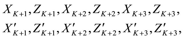
  output bits of the encoder are in the form:
 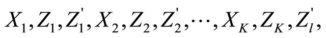 where
where  is the
  th systematic (i.e., data) bit,
  is the parity output from the upper (un interleaved) encoder, and
  is the parity output from the lower (interleaved) encoder. After the
  data bits have been encoded, the trellises of both encoders are forced back to the all-zeros state by the proper selection of tail bits. The tail bits of an RSC will depend on the state of the encoder. The tail bits are generated for each encoder by throwing the two switches into the down position, thus causing the inputs to the two
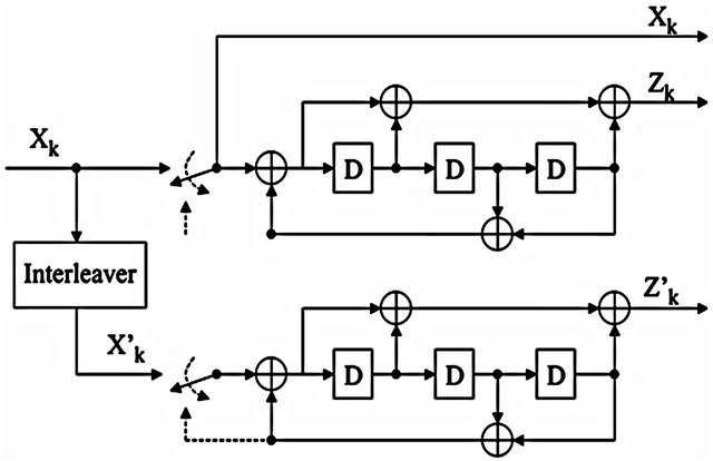
Figure 1. UMTS turbo encoder [3].
encoders to be indicated by the dotted lines. The tail bits are then transmitted at the end of the encoded frame according to
where  and
and  represents the tail bits of the upper and lower encoder,
  and
and  represents the parity bit of upper and lower encoder. Thus, when tail bits are taken into account, the number of coded bits is
 , and the code rate is
 .
.
3. Channel Model
BPSK modulation is assumed, along with either an AWGN or flat-fading channel. The output of the receiver’s matched filter is , where
  for the systematic bits,
  for the upper encoder’s parity bits,
  for the lower encoder’s parity bits,
  is the channel gain (
 for AWGN and is a Rayleigh random variable for Rayleigh flat-fading), nk is Gaussian noise with variance
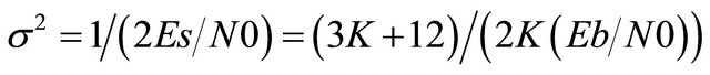 ,
,
 is the energy per code bit,
  is the energy per data bit, and
  is the one-sided noise spectral density. The input to the decoder is in the form
 (1)
(1)
By applying Bayes rule and assuming that 
 (2)
(2)
where  is the conditional probability density function (pdf) of
  given
given , which is Gaussian with mean
  and variance
 . Substituting the expression for the Gaussian pdf and simplifying yields
 (3)
(3)
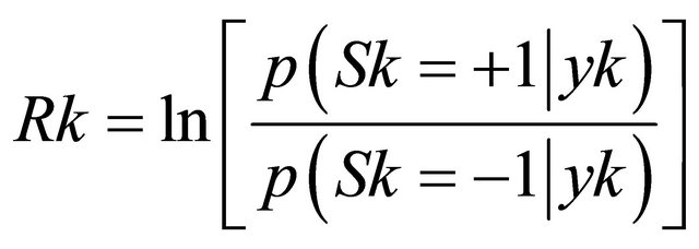
Thus, the matched filter coefficients must be scaled by a factor  before being sent to the decoder. The notation
  denotes the received LLR corresponding to systematic bit
 ,
,  denotes the received LLR for the upper parity bit
 , and
, and  denotes the received LLR corresponding to the lower parity bit
 .
.
4. Turbo Decoder
The architecture of the decoder is as shown in Figure 2.
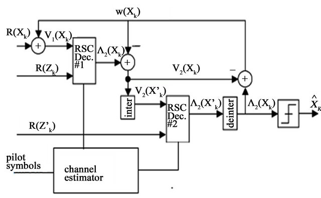
Figure 2. Proposed generalized turbo decoder architecture.
Decoding will be done in an iterative manner, because of the feedback [8]. Each full iteration consists of two half iterations, one for each constituent RSC code. The timing of the decoder is such that RSC decode#1 operates during the first half-iteration, and RSC decoder#2 operates during the second half iteration.
The value ,
,  , is the extrinsic information produced by decoder#2 and introduced to the input of decoder#1. Before to the first iteration,
  is initialized to all zeros. After each complete iteration, the values of
  will be updated to reflect beliefs regarding the data propagated from decoder#2 back to decoder#1.
  is not defined for
  so it will be taken as 0. The output of RSC decoder#1 is the LLR of
  that is obtained by
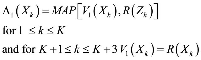
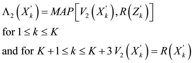
Similarly for decoder#2
Once the iterations have been completed, a hard bit decision is taken using , where
  when
when  and
and  when
when .
.
Here one modification is that a channel estimator as in [9], is attached with the decoder that will estimate channel condition through received pilot symbols [10,11]. Two RSC decoders choose the decoding process that will depend on the channel condition. Since for lower  log-map algorithm is used where high
  does not require it, so here we can use some linear approximation that will reduce complexity and increase throughput. The flowchart of decoding operation is given below:
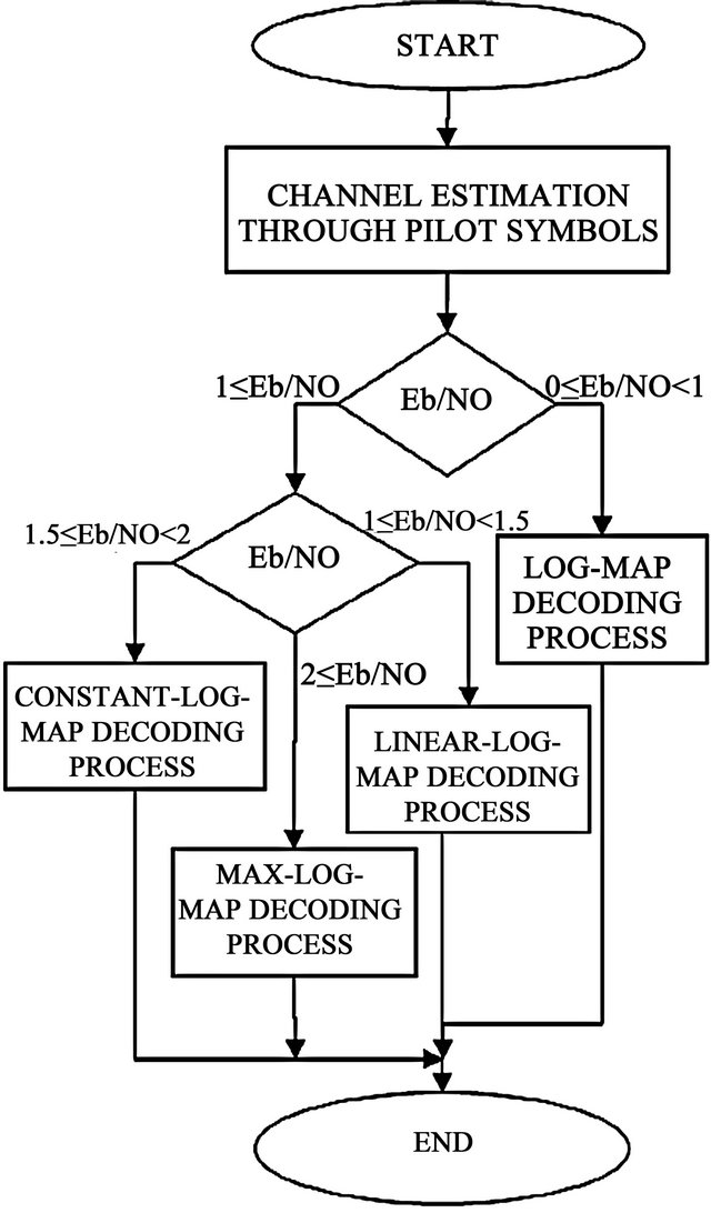
Flow chart for proposed turbo decoding process.
5. System Model
Each of the two RSC decoders in Figure 2 operates by sweeping through the code trellis twice, once in each of the forward and reverse directions. Each sweep uses a modified version of the Viterbi algorithm to compute partial path metrics, where the modifications is that the ACS operations are replaced with the max* operator. Here we use different algorithm technique for different channel condition.
5.1. Trellis Structure and Branch Metrics
The trellis of the RSC encoder used by the UMTS turbo code is shown in Figure 3 Solid lines indicate data  and dotted lines indicate data
 . The branch metric associated with the branch connecting states
  (on the left) and
  (on the right) is
 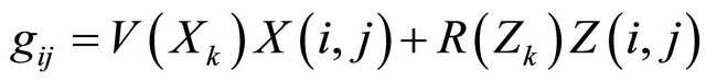 , where
  is the data bit associated with the branch and
  is the parity bit associated with the branch. Because the RSC encoder is rate
 , there are only four distinct branch metrics
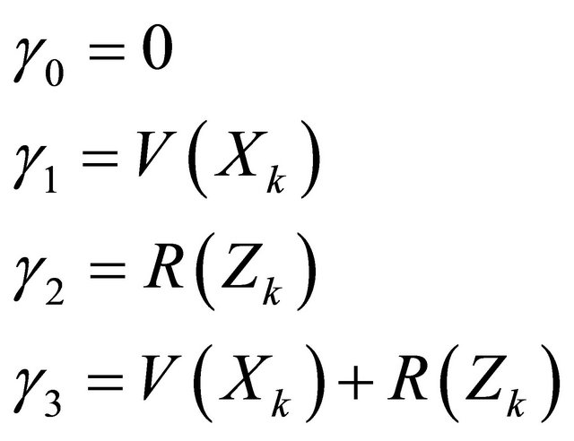 (4)
(4)
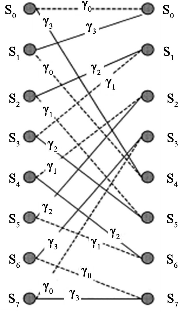
Figure 3. Trellis section for the RSC code used by the UMTS turbo code [3].
where for decoder#1  and for decoder #2
  and
and .
.
5.2. Backward Recursion
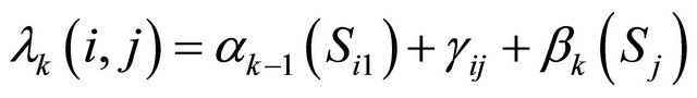
The proposed decoder begins with the backward recursion, saving normalized partial path metrics at all the nodes in the trellis (with an exception noted below),
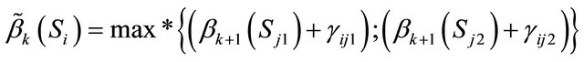 (5)
(5)
where the tilde above  indicates that the metric has not yet been normalized and
  and Sj2 are the two states at stage
  in the trellis that are connected to state
  at stage
 . After the calculation of
 , the partial path metrics are normalized according to
 (6)
(6)
Because after normalization ; for all
 , only the other seven normalized partial path metrics
 ,
,  , need to be stored. This constitutes a 12.5% savings in memory relative to either no normalization or other common normalization techniques (such as subtracting by the largest metric).
5.3. Forward Recursion
Beginning with stage  and proceeding through the trellis in the forward direction until stage
 , the unnormalized partial path metrics are found according to
 (7)
(7)
where  and
and  are the two states at stage
  that are connected to state
  at stage
 . After the calculation of
 , the partial path metrics are normalized using
 (8)
(8)
As the  are computed for stage
 , the algorithm can simultaneously obtain an LLR estimate for data bit
 . This LLR is found by first noting that the likelihood of the branch connecting state
  at time
  to state
  at time
  is
is
 (9)
(9)
The likelihood of data 1 (or 0) is then the Jacobi logarithm of the likelihood of all branches corresponding to data 1 (or 0), and thus where the max*operator is
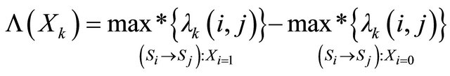 (10)
(10)
recursively over the likelihoods of all data 1 branches
or data 0 branches
 .
.
Once  is calculated,
  is no longer needed and may be discarded.
6. The Max* Operator
The RSC decoders in Figure 2 are each executed using a version of the classic MAP algorithm [12] implemented in the log-domain [13]. The algorithm is based on the Viterbi algorithm [4] with two key modifications: First, the trellis must be swept through not only in the forward direction but also in there verse direction, and second, the add-compare-select(ACS) operation of the Viterbi algorithm is replaced with the Jacobi logarithm, also known as the max* operator [14] here we consider four versions of the algorithm: log-MAP, max-log-MAP, constant-logMAP, and linear-log-MAP. The only difference among these algorithms is the manner in which the max* operation is performed.
6.1. Log-MAP Algorithm
With the log-MAP algorithm, the Jacobi logarithm is computed exactly using
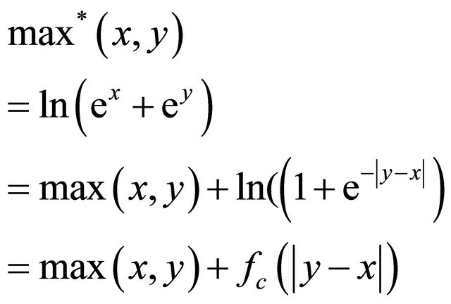 (11)
(11)
which is the maximum of the function’s two arguments plus a nonlinear correction function that is only a function of the absolute difference between the two arguments. The correction function . The logMAP algorithm is the most complex of the four algorithms when implemented in software, but it offers the best bit error rate (BER) performance.
6.2. Max-Log-MAP Algorithm
With the max-log-MAP algorithm, the Jacobi logarithm is loosely approximated using
 (12)
(12)
i.e., the correction function is not used at all. The max-log-MAP algorithm is the least complex of the four algorithms but offers the worst BER performance.
6.3. Constant-Log-MAP Algorithm
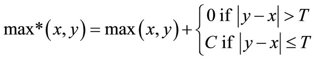
The constant-log-MAP algorithm, first introduced in [15]. It approximates the Jacobi logarithm using
 (13)
(13)
where it is shown in [16] that the best values for the UMTS turbo code are  and
and . In this algorithm correction function implemented by a 2-element look-up table.
6.4. Linear-Log-MAP Algorithm
This algorithm uses the following linear approximation to the Jacobi logarithm:
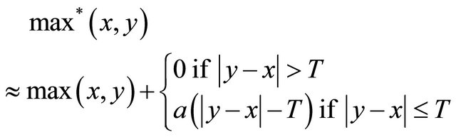 (14)
(14)
In [17],  and
and  can be find by minimizing the total squared error between the exact correction function and its linear approximation. Performing his minimization yields
  and
and .
.
7. Simulation Results
If we decode the same received frame by all four algorithm. The bit error rate (BER) is shown for the  bit UMTS turbo code in Figure 4 for 10 iteration. If the simulations were run to
 , an error floor would begin to appear. The beginning of a floor can be seen in the simulation of the
  bit code in AWGN channel [14]. Similarly, it can be seen in Rayleigh fading channel for higher
 . In the error floor region, all four algorithms will perform roughly the same. It can be seen in Figure 4 that the algorithms are beginning to converge as the BER curves begin to flare into a floor. Thus, while the choice of algorithm has
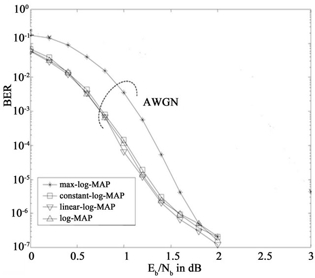
Figure 4. BER of K = 640 UMTS turbo code after 10 decoder iterations [3].
acritical influence on performance at low signal-to-noise ratio.
The choice becomes irrelevant at high SNR. This suggests that in a software implementation [18], perhaps the algorithm choice should be made adaptive (e.g., choose linear-log-MAP at low SNR and max-log-MAP at high SNR).
Regarding to above discussion we could make a generalized decoding process for AWGN channel which can decode as a log-MAP decoder when , linear-log-MAP decoder when
 , constant-log-MAP decoder when
 , maxlog-MAP decoder when
 . The proposed concept of generalization can be used in Rayleigh fading channel for higher
 .
.
The simulations were run on a PC with a 2.13-GHz Intel Core-i3 CPU and the 64 bit Windows 7 operating system for  and 10 decoder iteration. From the Figures 5 and 6 it is clear that BER performance little bit reduced in case of generalized decoding scheme but the overall throughput for generalized decoding is seven times greater than log-map decoding. Analysis also confirms that the log-MAP decoding algorithm is the least-efficient algorithm as compared to max-log-MAP algorithm in terms of processing power and computational delay; it is mainly due to complex process of calculating correction function for log-MAP decoder.
The other three algorithms are of similar complexities, with max-log-MAP shows minimal computational delay resulting in highest throughput per iteration. A comparison of the constant-log-MAP and linear-logMAP algorithms shows that there is the tradeoff between them in terms of complexity and performance. However, the linear-logMAP algorithm offers slightly better BER performance at the cost of slight reduction in overall throughput.
This type of generalised decoding algorithm can be use in software implimention for fixed number of iterations. From Figures 7 and 8 clearly shows that the as the number of iterations increases the BER decreases.
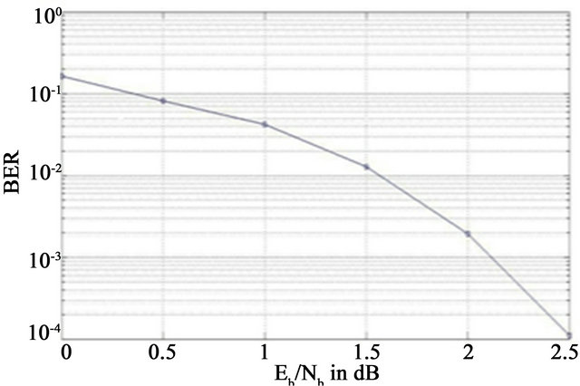
Figure 5. BER of K = 320 UMTS turbo code after 10 decoder iterations for generalized decoding.
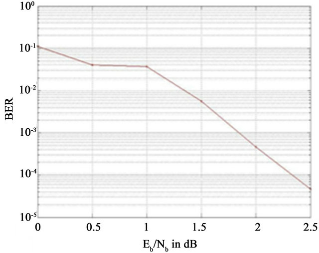
Figure 6. BER of K = 320 UMTS turbo code after 10 decoder iterations for Log-map decoding.
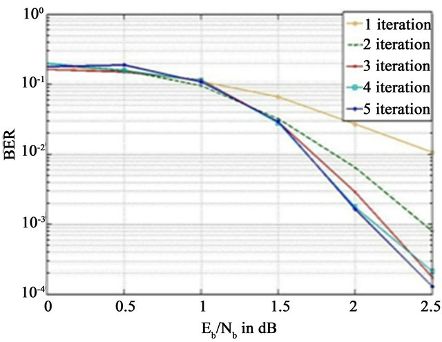
Figure 7. BER of K = 320 UMTS turbo code after 5 decoder iterations for generalized decoding.
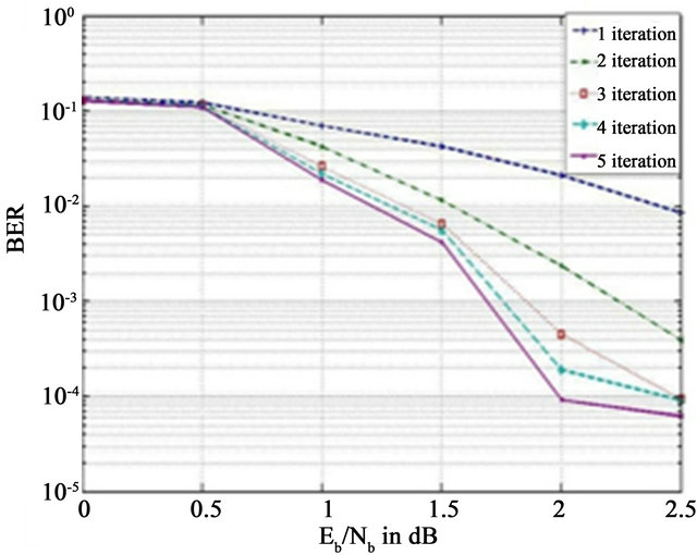
Figure 8. BER of K = 320 UMTS turbo code after 5 decoder iterations for log-map decoding.
8. Conclusion
In this paper, we propose a simple but effective adaptation of generalized turbo decoder. The proposed algorithm is characterized and evaluated through extensive simulation, showing that it optimizes the decoding performance with faster convergence. The simulation results shows that the adaptation of log-MAP based turbo decoding schemes offer better performance in terms of enhanced overall throughput with reduced complexity in comparison to the log-MAP algorithm. This has been achieved at the expense of only a modest increase in BER.
REFERENCES
- M. Guan and M. Yang, “Comparison and Design of Decoder in B3G Mobile Communication System,” Communications and Network, Vol. 1 No. 1, 2009, pp. 20-24. doi:10.4236/cn.2009.11003
- Y.-N. Lin, W.-W. Hung, W.-C. Lin, T.-J. Chen and E.-H. Lu, “An Efficient Soft-Input Scaling Scheme for Turbo Decoding,” IEEE International Conference on Sensor Networks, Ubiquitous, and Trustworthy Computing, Taichung, 5-7 June 2006, pp. 252-255. doi:10.1109/SUTC.2006.28
- M. C. Valenti and J. Sun, “The UMTS Turbo Code and an Efficient Decoder Implementation Suitable for Software-Defined Radios,” International Journal of Wireless Information Networks, Vol. 8, No. 4, 2001, pp. 203-215. doi:10.1023/A:1017925603986
- A. J. Viterbi, “Error Bounds for Convolutional Codes and an Asymptoticallyoptimum Decoding Algorithm,” IEEE Transactions on Information Theory, Vol. 13, No. 2, 1967, pp. 260-269. doi:10.1109/TIT.1967.1054010
- European Telecommunications Standards Institute, Universal Mobile Telecommunications System (UMTS), “Multiplexing and Channel Coding (FDD),” 3GPP TS 125.212 Version 3.4.0, 2000, pp. 14-20.
- S. Chronopoulos, G. Tatsis and P. Kostarakis, “Turbo Codes—A New PCCC Design,” Communications and Network, Vol. 3 No. 4, 2011, pp. 229-234. doi:10.4236/cn.2011.34027
- S. Rekh, S. S. Rani and A. Shanmugam, “Optimal Choice of Inter Leaver for Turbo Codes,” Academic Open Internet Journal, Vol. 15, 2005.
- S. Shah and V. Sinha, “Iterative Decoding vs. Viterbi Decoding: A Comparison,” Proceedings of the 14th National Conference on Communications NCCC 2008, Mumbai, 17 March 2008, pp. 491-493.
- M. Imani and H. Bakhshi, “Training Based Channel Estimation in MIMO-OFDM Systems,” Communications and Network, Vol. 4, No. 1, 2012, pp. 54-60. doi:10.4236/cn.2012.41008
- Y. Abdelkader and E. Jamal, “Optimal Spacing Design for Pilots in OFDM Systems over Multipath Fading Channels,” Communications and Network, Vol. 2 No. 4, 2010, pp. 221-229. doi:10.4236/cn.2010.24032
- M. Imani and H. Bakhshi, “The Tight Bound for the Number of Pilots in Channel Estimation for OFDM Systems,” Communications and Network, Vol. 4 No. 2, 2012, pp. 146-150. doi:10.4236/cn.2012.42019
- L. R. Bahl, J. Cocke, F. Jelinek and J. Raviv, “Optimaldecoding Oflinear Codes for Minimizing Symbol Error Rate,” IEEE Transactions on Information Theory, Vol. 20, No. 2, 1974, pp. 284-287.
- P. Robertson, P. Hoeher and E. Villebrun, “Optimal and Sub-Optimalmaximum a Posteriori Algorithms Suitable for Turbo Decoding,” European Transactions on Telecommunications, Vol. 8, No. 2, 1997, pp. 119-125. doi:10.1002/ett.4460080202
- A. J. Viterbi, “An Intuitive Justification and a Simplified Implementationof the MAP Decoder for Convolutional Codes,” IEEE Journal on Selected Areas in Communications, Vol. 16, No. 2, 1998, pp. 260-264. doi:10.1109/49.661114
- W. J. Gross and P. G. Gulak, “Simplified MAP lgorithm Suitablefor Implementation of Turbo Decoders,” Electronics Letters, Vol. 34, No. 16, 1998, pp. 1577-1578. doi:10.1049/el:19981120
- B. Classon, K. Blankenship and V. Desai, “Turbo Decoding with the constant-Log-MAP Algorithm,” Proceedings International Symposium on Turbo Codes and Related Topics, Brest, 4-7 September 2000, pp. 467-470.
- J. F. Cheng and T. Ottosson, “Linearly Approximated Log-MAP Algorithms for Turbo Decoding,” IEEE Proceedings of Vehicular Technology Conference (VTC) (Houston, TX), Tokyo, 15-18 May 2000, pp. 2252-2256.
- S. Choudhury, “Modeling and Simulation of a Turbo Encoder and Decoder for Wireless Communication Systems,” UT Austin, 2002.