Communications and Network
Vol.3 No.1(2011), Article ID:3986,9 pages DOI:10.4236/cn.2011.31002
Efficient Power Loading in MIMO-OFDM Based Cognitive Radio Networks
Dept. of Electrical Engineering, K. N. Toosi University of Technology, Tehran, Iran
E-mail: shahrokh@ee.kntu.ac.ir
Received November 3, 2010; revised December 23, 2010; accepted December 25, 2010
Keywords: MIMO, OFDM, Power Allocation, SVD
Abstract
Due to their spectrum shaping capability and high adaptability, the multi-carrier systems are considered as prime candidates for use in the Cognitive Radio (CR) networks. In these structures, the deactivation of the primary users’ (PUs) bands makes the secondary users (SUs) use a limited number of sub-carriers, so the total capacity of CR networks is reduced. However, multiple transmit antennas can be applied to OFDMbased CR to compensate for such a low capacity. The present study investigates the problem of power allocation in MIMO-OFDM based CR Networks. The objective is maximizing the total capacity of CR systems in the downlink path under both interference on the PUs’ bands and maximum power of the CR transmitter constraints. It is shown that the optimal solution has high computational complexity, and therefore, an efficient sub-optimal algorithm is suggested for this application. As simulation results show, the suggested algorithm in the present paper is more enhanced and efficient than the previous algorithms.
1. Introduction
In the conventional wireless networks, the allocation of the frequency bands is constant, that is, the entire frequency band is managed by a single committee (FCC) and each band provides a specific kind of service. It seems that the constant allocation of the frequency band cannot supply the increasing demands for frequency bands. On the other hand, as reported in the literature, a large part of the spectrum (whether allocated or not) remains unused over different periods of time [1]. A lack of frequency resources and their improper use stress a need for a significant change in the frequency band allocation. One useful method is to provide a use of the unused parts of the spectrum for the secondary users. To do so, the cognitive radio has recently been introduced, which attracted much attention [2,3].
Cognitive radio is indeed an intelligent wireless system which recognizes the spectrum traffic condition in ambience at any moment and can thus adjust its interior parameters such as transmitter’s power, carrier’s frequency, modulation type etc.
To provide service for the secondary users, cognitive radio should first gather the information on the spectrum and determines the spectrum holes. After recognizing the unused parts of the spectrum, the most important duty of the CR networks is to determine how the secondary users use these holes. Different strategies have thus been proposed for this problem known as the spectrum sharing. In terms of access to the spectrum, these structures are generally divided into Underlay spectrum sharing and Overlay spectrum sharing [3].
Spectrum Pooling is one of the best proposed methods to utilize the spectrum efficiently in Overlay systems. In this method, keeping the primary networks unchanged, the secondary users are allowed to use the spectrum holes. Generally, each user in the CR network transmits its measured information to the CR base-station during the detection cycle and this station plans a general spectrum allocation scheme for opportunistic usage [4].
Among many possible technologies for the secondary users’ transmission in the spectrum pooling systems, OFDM (Orthogonal Frequency Division Multiplexing) has already been widely recognized as a particularly promising candidate. This is mainly due to its great flexibility in dynamically allocating the unused spectrum among secondary users as well as its ability to monitor the spectral activities of the licensed users at no extra cost [5-7]. However, because the sub-carriers are deactivated on the PUs’ bands, the number of sub-carriers used by the secondary users in such a structure is limited. So, the total capacity of the CR networks is limited.
The multiple transmit antennas can be applied to OFDM-based CR, as this technique may increase the CR network capacity [8,9]. The combination of MIMO (Multiple-Input Multiple-Output) and OFDM, which is called MIMO-OFDM, has attracted great attention recently. In a hybrid scheme, MIMO is used to increase the capacity and diversity gain, while OFDM is used to transform frequency selective channel of MIMO to flat fading sub-channels [10,11].
In our previous work [12], we have introduced the MIMO-OFDM structure as a physical layer in order to increase the capacity of CR networks. Moreover, it has been shown that the traditional power allocation algorithms in MIMO-OFDM systems are not effective enough in CR networks due to mutual interference between the primary and the secondary users. Therefore, regarding the interference constraint on primary users’ bands, an efficient power loading algorithm for this system was extracted. This algorithm considered not only channel state condition but also total interference limitation.
But in most cases, in addition to the interference constraint on primary users’ bands, there is a constraint related to the maximum transmittable power of the transmitter. Therefore, through the present study, in addition to the interference constraint, the constraint on the maximum power that can be transmitted by the transmitter has been regarded. It will be shown that finding the algorithm for optimal power allocation is a highly complex matter which makes its practical applications impossible. Therefore, a sub-optimal algorithm which can be implemented has been introduced in this scenario.
Simulation results show that the power allocation algorithm suggested by the present paper is more effective in applying to CR networks than the previous ones.
The paper is organized as follows: Section 2 describes and investigates present conditions and limitations of the considered system to reach its maximum capacity. The optimal power allocation profile is investigated, and main scheme obtained theoretically in Section 3. In Section 4, we propose a sub-optimal power allocation algorithm, and its different stages are shown. A most popular power allocation algorithm in conventional MIMOOFDM systems is considered in Section 5. Section 6 compares the performance of the new algorithm with previous methods in the considered system and finally, the conclusions are drawn in Section 7.
2. System Description
A one-cell wireless system, where the PU and SU transceivers coexist in the same geographical location, is assumed. The Scenario is illustrated for a downlink path and one CR user. Primary users’ base-station transmits signals to U primary users, each of which occupies a determined frequency band in the available spectrum. The CR network has an individual base-station that identifies the spectrum holes on the basis of the information collected about spectrum and then inactivates the primary users’ sub-carriers and transmits its users’ information by the remaining sub-carriers (Figure 1).
It is assumed that the perfect channel state information (CSI) is available at the SU’s receiver side after channel estimation, and a signaling channel is used to feedback the CSI to the corresponding transmitter. The perfect channel state between the SU and a specified PU is also available by sensing the channel or searching in a pre-established database.
Suppose that the CR base-station and the CR user have  and
and  antennas, respectively. The SU’s MIMO channel for
  subcarrier is denoted by an N × M matrix
 , where its element
  denotes the channel gain between
  transmit and
  receive antenna. The channel gain between the SU’s transmitter and
  PU’s receiver for
  subcarrier is denoted by a 1 × M matrix
 , where
  denotes the channel gain between SU’s
  transmit antenna and the
  PU receiver antenna.
Because it is assumed that the transmitter has the perfect channel state information, each sub-carrier channel can be decomposed into parallel independent sub-channels by SVD (Singular Value Decomposition) [13]. It can be expressed as:
 (1)
(1)
where  and
and  are unitary matrices and
  is a rectangular matrix whose diagonal elements are non-negative real numbers. The diagonal elements
  are the ordered singular values of the matrix
 , where
 .
.
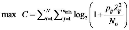
These sub-channels are characterized by the channel gains, which are the singular values of the MIMO channel matrix on each sub-carrier. By multiplexing independent data onto these independent channels, the capacity of  sub-carrier can be obtained by:
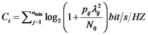 (2)
(2)
Where  is the Additive White Gaussian Noise (AWGN) variance and
  denotes the transmit power at the
  antenna of
  sub-carrier. In an adaptive structure, to achieve maximum capacity, power of the transmitted symbol on each of the parallel sub-channels is allocated optimally.
2.1. Interference Limitation on Primary Users’ Bands
As mentioned before, in the considered MIMO-OFDM structure, OFDM structure is ultimately used to transmit data. Due to the orthogonality among the sub-carriers, inter-carrier interference among the CR sub-carriers can be ignored. However, because the active primary systems do not necessarily use OFDM structure, CR data transmission may cause some interference on the primary users’ bands, which is elaborated below.
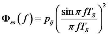
Assume the transmit signal on the  antenna of
  sub-carrier is a rectangular non-return-to-zero signal. The power spectral density (PSD) of this signal can be modeled as [14]:
 (3)
(3)
Where  is the total transmit power on the
  antenna of
  sub-carrier, and
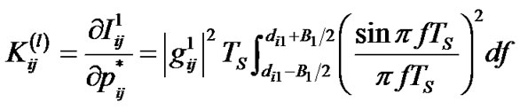
  is the symbol duration. The resulting interference power spilling into the
  PU’s sub-carrier is given by:
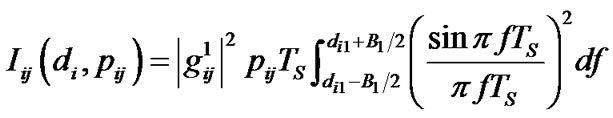 (4)
(4)
where  denotes channel gain from the CR base-station to the
  PU sub-carrier for
  antenna of
  sub-carrier.
  represents the frequency distance between the
  sub-carrier of CR user band and the
  PU’s sub-carrier, and
  represents each subcarrier’s bandwidth.
Moreover, the coexistence of the primary and secondary users may causes interference induced by the signals from primary BS, which are destined for primary users, onto secondary users’ frequency bands. Nevertheless, primary users’ transmitters in the present analysis have not be considered as the paper is concerned with the power loading at CR transmitter and with interference from CR transmitter in primary users’ receivers.
As Equation (4) shows, such interference on the primary users’ bands depends on both the power of CR sub-carriers and the distances between the CR sub-carriers and the primary bands.
Much attention has been paid before to Power allocation for downlink MIMO-OFDM-based systems. However, due to mutual interferences between CR and primary networks, such power allocation methods are not sufficiently effective in CR networks. Thus, it is necessary that new and effective power allocation algorithms be studied in order to maximize the capacity of CR networks where both the channel state conditions and the total interference limitation are regarded.
3. Optimal Power Allocation
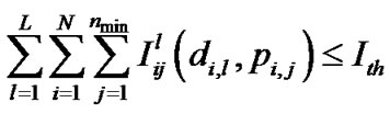
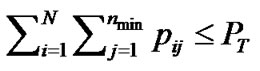
As we discussed in previous section, our purpose is to introduce a new power allocation algorithm that maximizes the total capacity of CR system provided caused interferences into the primary users’ bands do not exceed from a certain level and also a constraint related to the maximum transmittable power of the transmitter.
This problem can be formulated as the following problem (P1):
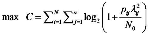 (5)
(5)
Subject to

Problem (P1) is an optimization problem, which can be solved using KKT method [15]. Considering the Lagrange multipliers as  ،
، and
and , KKT’s conditions can be expressed as:
 (6-1)
(6-1)

 (6-2)
(6-2)
 (6-3)
(6-3)
 (6-4)
(6-4)
 (6-5)
(6-5)
 (6-6)
(6-6)
 (6-7)
(6-7)
 (6-8)
(6-8)

Equation (6-1) can be rearranged as:
 (7)
(7)
Since , then
 (8)
(8)
If
 then
then  and hence
If  from (8)
Which implies  and from (6-8)
 .
.
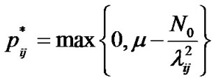
Therefore, the optimal solution can be written as:
 (9)
(9)
where .
.
Determining the amount of the optimal power which should be allocated for an antenna of a sub-carrier by use of equation (9) demands some complex and time consuming calculations. Indeed, in order to find such an optimal amount, problem (9) has to be solved employing interior point methods. Due to the considerable complexity of such iterative methods, the algorithm (9) seems to be unsuitable for practical applications. So, the next section devises a sub-optimal method for solving the problem (P1) which can be easy to use in practice.
4. Sub-Optimal Power Allocation
In this section, a sub-optimal algorithm for power allocation concerning interference on PUs’ bands and the maximum transmittable power of the transmitter is proposed. Problem (P1) is thus considered.
Clearly, if the second constraint is disregarded from (P1), the problem changes into the problem which we investigated it in our previous work [12].
It has been shown that this problem is a convex optimization problem and has the following multi–level water-filling solution [12]:
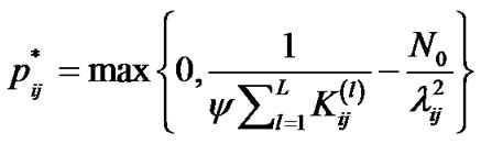 (10)
(10)
where
 and
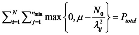
and  is Lagrange’s multiplier and can be computed as:
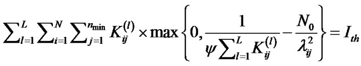 (11)
(11)
Using the above scheme, the optimal power allocation policy can thus be obtained so that it maximizes the transmission capacity of CR users while keeping the interference introduced to the primary users below the specific threshold.
On the other hand, assuming the interference constraint is omitted from (P1); the problem changes into power allocation problems in conventional MIMOOFDM systems. In this case, the optimal solution allocates the power using Water-filling method which in turn results in a maximum capacity for the system. This method is addressed in the next section.
With regard to the above mention, the suggested suboptimal algorithm first assumes that no transmit power constraint is existing and the only constraint of the problem is the interference onto the primary users’ bands. Consequently, the maximum power which can be allocated for a branch ( ) is determined using equations(10) and (11). It should be noted that the obtained power values are in such a way that guarantees the interference onto primary users’ bands does not exceed a tolerable range.
In the next step, regarding the maximum transmittable power of the transmitter and also the maximum allowable power for each branch, which was determined in the previous step, power is allocated so as to maximize the total capacity of the system. It can be given by the following optimization problem (P2):
 (12)
(12)
Subject to


The problem (P2) is again a convex optimization problem which can be solved using standard methods. Lagrange multipliers are considered as  ،
، and
and . So, KKT equations are as:
(13-1)


(13-2)

(13-3)

(13-4)
(13-5)
(13-6)
On the assumption of  then the following implication take place:

Therefore, (13-6) results in:

So that (13-1) leads to
 (14)
(14)
Since  and
and  then
then
 . (15)
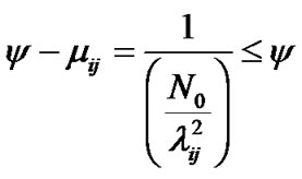
Thus, to solve the optimization problem, different states are considered as below:
If  then from (13-5) and (13-6)
As a result, (13-1) gives:
 (16)
(16)
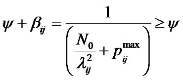
If  then from (13-6)

and from (13-1)
 (17)
(17)
Since 
If  then from (13-5)

and from (13-1)
 (18)
(18)
Since .
.
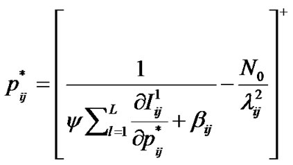
Therefore, according to equations (16-18), the allowable power for each branch in terms of different values of  can be summarized as follows:
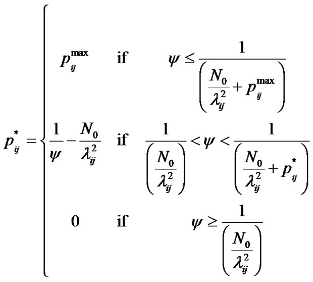 (19)
(19)
Equation (19) can be restated as:
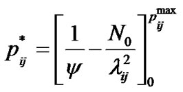 (20)
(20)
in which
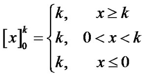 (21)
(21)
The value of  in Equation (20) is also obtained from:
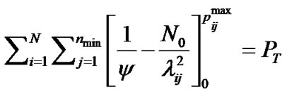 (22)
(22)
It should be noted that if  is omitted from Equation (20) that is, no limitation is imposed on the allowable power allocated to each branch, the algorithm changes into the conventional water-filling algorithm. Indeed, Equation (20) represents a cap limited waterfilling algorithm so that at any stage the optimal power allocated for each branch in relation to the total power constraint is determined using water-filling algorithm. If the allocated power for a branch is more than its maximum permissible power,
  , it is clipped in the same amount as
 . Besides, Equation (20) clearly indicates that in the branches with the higher ratio of
 , it is more probable that the value of their allocated power is higher than
 . Thus, they have a greater chance to be clipped.
Sub-optimal power allocation algorithm steps can be summarized as below:
1) By the first stage, the maximum transmittable power is disregarded and the optimal power of each branch  is determined using equations (10) and (11).
2) If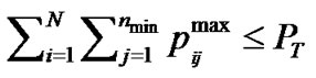 , then the power of each branch is the same as the determined power in stage 1, so power allocation is finished.
3) If , then power allocation is as:
All branches are sorted in a descending order on the bases of .
.
where,  is the branches’ index,
  are the sorted
 values,
  are the sorted indices and
  is the number of branches.
While  do
do
• According to the constraint related to the maximum power of the transmitter , the conventional water-filling algorithm is used and the power of each branch in the set
  is determined.
• 
• 
• 
End while Using the above mentioned algorithm, the interference onto primary users’ bands and maximal transmit power are considered so that the total capacity of the system is maximized.
However, it is important to note that some branches cannot reach the maximal power determined by the interference constraint owing to the maximum transmittable power constraint. Using the above algorithm, the total of the caused interference onto primary users’ bands is less than the threshold .
.
5. Traditional Power Loading Schemes
In this section, uniform power loading, the most popular power allocation algorithm in conventional MIMOOFDM systems, is considered.
According to uniform power loading policy, the total transmit power is allocated equally among all the subcarriers. Then to achieve maximum capacity, power is allocated by using water filling algorithm among MIMO antennas.
In order to make a fair comparison with the new scheme, both new sub-optimal and uniform-water filling schemes should maintain a given interference threshold. Then it would be interesting to observe which scheme offers a higher transmission rate for the CR user.
Therefore, for a fair comparison, at first we determine how much power can be transmitted using a uniform power allocation scheme for a given interference threshold. Then this total power is divided equally among the sub-carriers. Hence the power in the  sub-carrier can be obtained as:
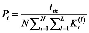
Where  is the amount of power, which can be allocated to the
  sub-carrier for the given interference threshold.
 (23)
(23)
In the next stage, by using the power that has been allocated above for each sub-carrier, power of each MIMO antennas is allocated in the way that the capacity of each sub-carrier maximize and as a result, the total capacity maximize. To do this, following optimization problem should be solved for each sub carrier:
 (24)
(24)
Subject to


It has been shown that the above problem has the following water-filling solution [13]:
 (25)
(25)
where  is Lagrange’s indicator and can be computed as:
 (26)
(26)
6. Simulation Results
Using computer simulations, this section evaluates and compares the proposed power allocation method with the previous methods in the cognitive radio networks.
The simulations are carried out for a MIMO-OFDMbased CR system under the scenario given in Figure 1. The total spectrum band is divided into sub-channels, each of which is equal to 1MHZ bandwidth and is allocated to an OFDM sub-carrier. It is assumed that the frequency bands, occupied by the primary users, are known in the CR base station, and active sub-carriers have been determined as shown in Figure 2. Both CR base-station and CR user can have different numbers of antennas.
Furthermore, 32 sub-carriers have been considered so that 16 of them are used by primary users and the rest of them are used by CR network in three equal bands, as shown in Figure 2.  and
and  are assumed to be
  and 1 MHz, respectively. Additive White Gaussian Noise of variance 10−3 is assumed and channel gains h and g are assumed to be Rayleigh fading with an average power gain of 1 dB.
The simulations have been run concerning both the interference on the primary users’ bands and the maximal transmittable power of the transmitter. The maximum transmittable power of the transmitter is assumed to be 1 watt. Each simulation has been run 1000 times and shown values are the average of these results.
Figure 3 shows the maximum capacity versus the interference imposed on the PUs’ bands for a 4 × 4 CR system under the given scenario. The maximum capacity attained by the suggested sub-optimal algorithm of section 4 has been shown and compared with the results of the conventional water-filling algorithm in this figure.
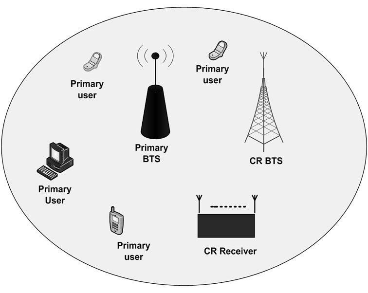
Figure 1. Coexistence of primary and secondary networks in cognitive radio.
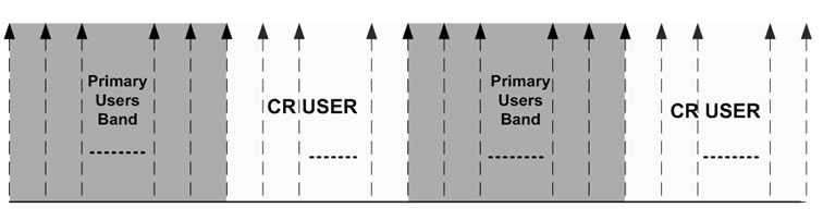
Figure 2. Distribution of available spectrum to primary and secondary users.
Besides, for the evaluation of the performance of the sub-optimal algorithm, the results of the optimal algorithm (Equation (10) and Equation (11)) related to the scenario with no constraint of the transmittable power have been shown here.
According to figure 3, in comparison with the conventional water-filling algorithm, the sub-optimal algorithm delivers a very good performance.
Moreover, a comparison of the performance of the sub-optimal algorithm with the scenario in which there is no power constraint yields in the following results. In the cases that the amount of power which can be allocated to CR network is lower than the maximum transmittable power of the transmitter (i.e., when the threshold level is lower than 0.008 watt), both of the algorithms give the same performance. With an increase in this interference threshold, the total capacity of the CR network under the scenario with both power and interference constraints decreases versus the other scenario. The reason is that with higher tolerable interference threshold levels more power can be allocated to CR network in the scenario with only interference constraint, whereas the scenario of this paper cannot use such a power due to the transmittable power constraint.
Figure 4 shows the simulation results for the case that there are two antennas in the CR transmitter and two in the CR receiver, which verifies the above mention.
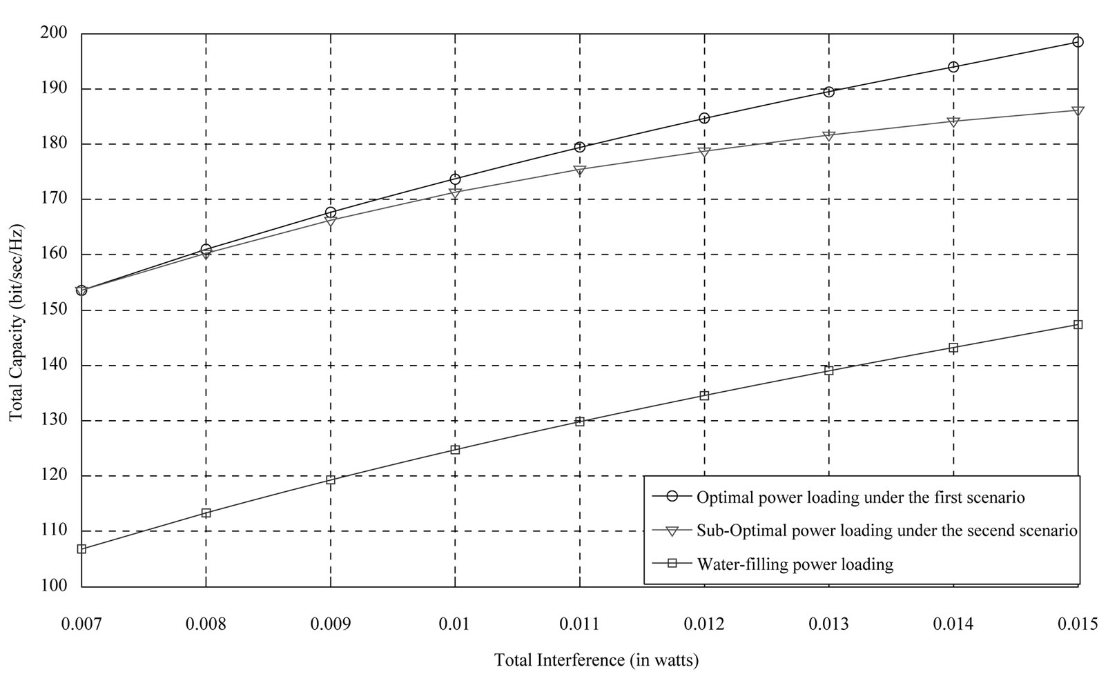
Figure 3. Maximum capacity of CR user versus interference introduced to the primary users band for a  CR system.
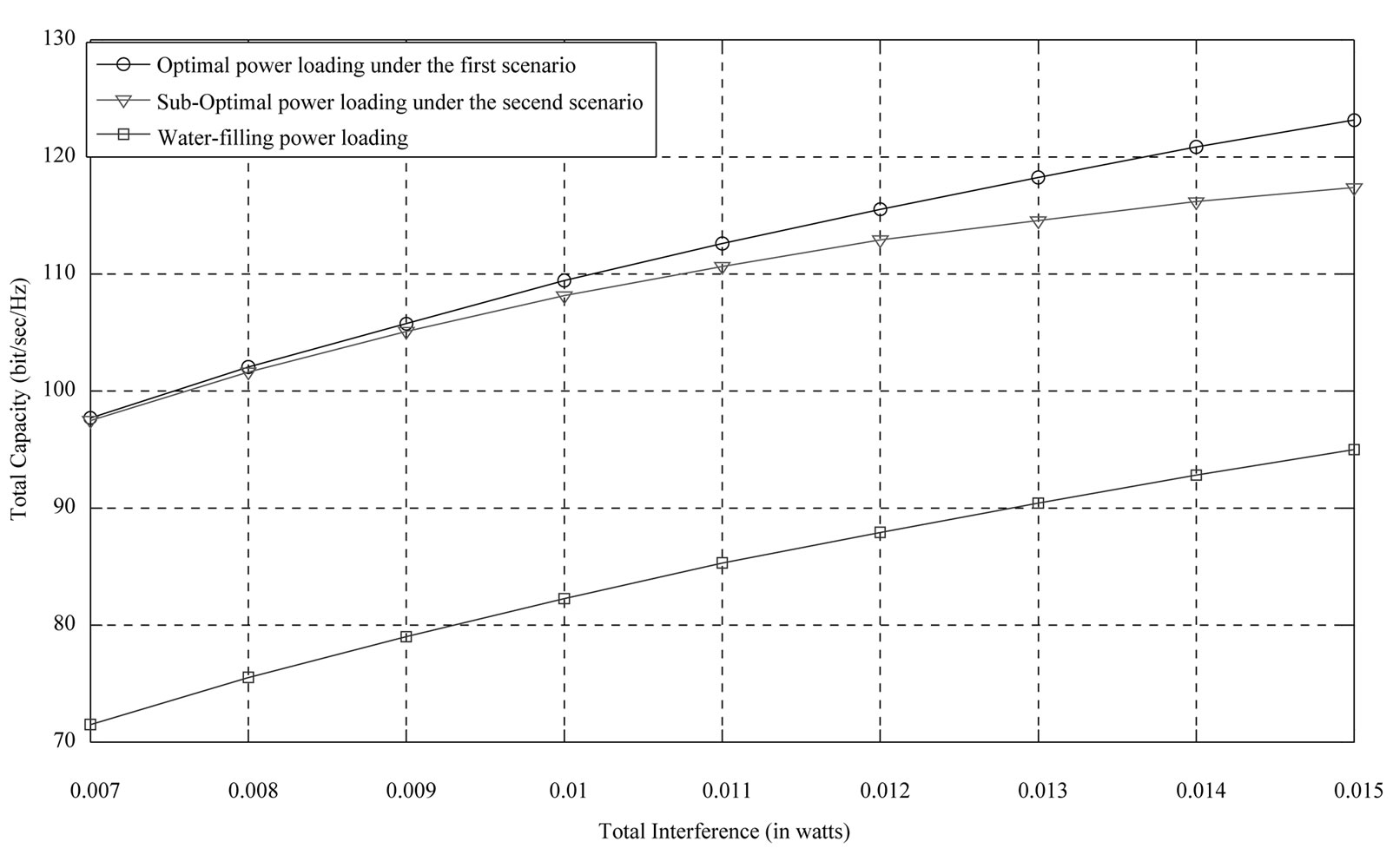
Figure 4. Maximum capacity of CR user versus interference introduced to the primary users band for a  CR system.
7. Conclusion
This paper has investigated the power loading scheme for the Cognitive Radio Networks utilizing the MIMOFDM structure. It has been shown analytically that the conventional power loading algorithm cannot be used in the Cognitive Radio Networks. Therefore, the problem of power allocation has been studied under a given scenario. It has been shown that under this scenario, the optimal algorithm is such a complex problem that cannot be practically implemented. Accordingly, a sub-optimal algorithm ensuring practical implementation has been proposed. Through the simulation results, the performance of the new power loading algorithm has been evaluated and compared with the previous ones. It has been shown that the new algorithm is more efficient and suitable to apply in the CR networks.
8. Acknowledgment
This work has been sponsored by Iranian Research Institute for ICT (ITRC).
9. References
[1] Federal Communication Commission, “Spectrum Policy Task Force,” Report of ET Docket 02-135, November 2002.
[2] S. Haykin, “Cognitive Radio: Brain-Empowered Wireless Communications,” IEEE Journal on Selected Areas in Communications, vol. 23, No. 2, February 2005, pp. 201- 220. doi:10.1109/JSAC.2004.839380
[3] F. Akyildiz, W. Y. Lee, M. C. Vuran and S. Mohanty, “Next Generation/Dynamic Spectrum Access/Cognitive Radio Wireless Networks: A Survey,” Computer Networks, vol. 50, No. 13, September 2006, pp. 2127-2159. doi:10.1016/j.comnet.2006.05.001
[4] T. A. Weiss and F. K. Jondral, “Spectrum Pooling: An Innovative Strategy for the Enhancement of Spectrum Efficiency,” IEEE communications Magazine, Vol. 43, March 2004, pp. S8-14. doi:10.1109/MCOM.2004.1273 768
[5] R. V. Nee and R. Prasad, “OFDM for Wireless Multimedia Communication,” Artech House, London, 2000.
[6] U. Berthold, F. Jondral, S. Brandes and M. Schnell, “OFDM-Based Overlay Systems: A Promising Approach for Enhancing Spectral Efficiency [Topics in Radio Communications],” IEEE Communications Magazine, vol. 45, no. 12, December 2007, pp. 52-58. doi:10.1109/ MCOM.2007.4395365
[7] B. Farhang-Boroujeny and R. Kempter, “Multicarrier Communication Techniques for Spectrum Sensing and Communication in Cognitive Radios,” IEEE Communications Magazine, Vol. 46, No. 4, April 2008, pp. 80-85. doi:10.1109/MCOM.2008.4481344
[8] A. J. Paulraj, et al., “An Overview of MIMO Communications—A Key to Gigabit Wireless,” Proceedings of the IEEE, Vol. 92, No. 2, February 2004, pp. 198-218.
[9] D. Gesbert, M. Shafi, D. Shiu, P. J. Smith and A. Naguib, “From Theory to Practice: An Overview of MIMO Space–Time Coded Wireless Systems,” IEEE Journal on Selected Areas in Communications, Vol. 21, No. 3, April 2003, pp. 281-302. doi:10.1109/JSAC.2003.809458
[10] H. Bolcskei and E. Zurich, “MIMO-OFDM Wireless Systems: Basics, Perspectives, and Challenges,” IEEE Wireless Communications, Vol. 13, No. 4, August 2006, pp. 31-37. doi:10.1109/MWC.2006.1678163
[11] W. Zhang, X. G. Xia and K. B. Letaief, “SpaceTime/Frequency Coding for MIMO-OFDM in Next Generation Broadband Wireless Systems,” IEEE Wireless Communications, Vol. 14, No. 3, June 2007, pp. 32-43. doi:10.1109/MWC.2007.386610
[12] H. Shahrokh and K. Mohamedpour, “Power Allocation in MIMO-OFDM Based Cognitive Radio Networks,” Accepted for publication in IET Communication Journal, 2010.
[13] D. Tse and P. Viswanath, “Fudamental of Wireless Communication,” Cambridge University Press, Cambridge, 2005.
[14] T. A. Weiss, J. Hillenbrand, A. Krohn and F. K. Jondral, “Mutual Interference in OFDM-Based Spectrum Pooling Systems,” IEEE 59th Vehicular Technology Conference, 2004, pp. 1873-1877.
[15] S. Boyd and L. Vandenberghe, “Convex Optimization,” Cambridge University Press, Cambridge, 2004.