World Journal of Condensed Matter Physics
Vol.2 No.1(2012), Article ID:17630,6 pages DOI:10.4236/wjcmp.2012.21002
Simple Preparation and Characterization of Nano-Crystalline Zinc Oxide Thin Films by Sol-Gel Method on Glass Substrate
![]()
1Department of Applied Physics, Chongqing University, Chongqing, China; 2Key Laboratory of Optoelectronic Technology and Systems of the Education Ministry of China, Chongqing University, Chongqing, China; 3Department of Applied Physics, Chongqing Normal University, Chongqing, China.
Email: *saleem.malikape@gmail.com
Received September 5th, 2011; revised October 5th, 2011; accepted October 15th, 2011
Keywords: Sol-Gel Method; Spin Coating; XRD; SEM; EDS; Optical Properties
ABSTRACT
Nanocrystalline ZnO thin films have been fabricated by a multi-step sol-gel method using spin coating technique. Zinc acetate dihydrate, 2-methoxyethanol and monoethanolamine were used as a starting material, solvent and stabilizer, respectively. X-Ray Diffraction (XRD) and Scanning Electron Microscopy (SEM) were employed to characterize structure and morphologies of the as-deposited samples. The results of XRD and SEM showed that the heat treatment conditions, final rotational (spinning) speed, fume exhaust and precise control of concentration of reactants (precursor and solvent used) strongly affect the crystallographic orientation and morphology of the resultant ZnO films. The XRD pattern showed that the ZnO films formed the preferred orientation along c-axis and the grain size is 16nm for the samples. Only one peak corresponding to the (002) plane at 2θ = 34.34˚ appears on the diffractograms. The as-deposited films had a transparency of greater than 80% in the visible-near IR region from 400 nm - 800 nm. The optical band gap energy and thickness were calculated to be 3.296 eV and 266 nm respectively.
1. Introduction
ZnO is an inexpensive n-type of II-VI semiconductor compound, which has technical applications such as photo-catalysts [1], thin film gas sensors [2], varistors [3], light emitting diodes [4], spintronic devices [5], nanolasers [6]. ZnO thin films have also been widely used as surface acoustic wave (SAW) device and film bulk acoustic resonator (FBAR) because of its excellent piezoelectric properties [7,8]. Its stability in hydrogen plasma [9] culminated in its exhaustive use as window layer for polycrystalline solar cells [10-12] and silicon thin film solar cells [13-15]. Moreover, ZnO has large band gap 3.37 eV, large excitonic binding energy 60 meV and high carrier mobility at room temperature. ZnO is composed of hexagonal wurtzite crystal structure with unit cell a = 3.253 Å and c = 5.215 Å due to their unique optical, electrical and semi-conducting properties, ZnO thin films form the mainstay of the electronics industry and the cornerstone of modern technology.
Nanostructures of ZnO are fabricated using various thin film techniques as sputtering [16], spray pyrolysis [17], metal-organic chemical vapour deposition (MOCVD) [18], molecular beam epitexy (MBE) [19], pulsed laser deposition (PLD) [20] and the sol-gel process [21-27]. Sol-gel method is widely adopted for the fabrication of transparent and conducting oxide due to its simplicity, safety, no need of costly vacuum system and hence cheap method for large area coating. The sol-gel process also offers other advantages such as high surface morphology at low crystallizing temperature, the easy control of chemical components and fabrication of thin film at low cast for elucidating the structural and optical properties of ZnO thin film. The fabrication of doped and un-doped ZnO thin films by the sol-gel process has already been reported by many researchers [24-27]. However, up to date, multiple deposition steps have been generally necessary to produce thin films of high-quality. In order to obtained high-quality films, a typical multi-step deposition process has been demonstrated.
In the present work, nanoycrystalline ZnO films have been produced by the sol-gel method using zinc acetate precursor and their surface morphologies, preferential orientation and optical properties were studied in detail.
2. Materials and Methods
2.1. ZnO Sol-Gel Preparation
The sol-gel synthesis and thin film process arrangement is shown schematically in Figure 1. Zinc acetate dehydrate (Zn(CH2COO)2·2H2O) (ZAD), 2-methoxyethanol (CH3O (CH2)2OH) (2-ME) and monoethanolamine ((HOCH2CH2) NH2) (MEA) were used as starting material, solvent and stabilizer, respectively. The mixture was confected to 0.5 mol·L–1 and stirred magnetically. After stirring for 30 minutes at 60˚C, MEA was added drop by drop under constant stirring. The resultant solution was stirred for 90 minutes. to yield a colorless, homogeneous and transparent solution. The solution was aged for 72 hours at room temperature in order to make it more glutinous. The molar ratio of MEA to ZAD was maintained at 1:1. Prior to the coating of the film, the glass substrates were sonicated or washed with detergent, and then cleaned in methanol and acetone for 5 minutes each. Afterwards, substrates were rinsed with distilled water and then dried in hot air. The aged solution was dropped on glass substrates which were rotated at 2000 rpm for 30 seconds. The as-deposited films were then pre-heated at 200˚C for 10 minutes into a furnace to evaporate the solvent and remove organic residuals. This spinning to preheating procedure was repeated eight times. After the deposition of final layer, films were calcined in air at 400˚C for 1hour to ensure that all organic species were expelled from the films.
2.2. Material Characterization
X-ray diffraction (XRD) was used for the physical structure (crystalline structure and microstructure) of the ZnO thin films. XRD patterns were obtained with a MRD-Single Scan diffractometer with Cu Kα (λ = 1.54056Å) radiation and scanning range of 2θ set between 20˚ and 80˚. During the measurement, the current and the voltage of XRD were maintained at 20 mA and 36 KV respectively, and scan speed was 4˚/min. The surface morphology of films was evaluated using Scanning electron microscopy (FEG-SEM, Nova-400). The thickness of the film was measured by a surface profilometer (AMBIOS).
The transmission spectra of the films were measured by a double-beam ultraviolet/visible (UV-4100) spectrophotometer with a wavelength range 200 nm - 800 nm and the optical band gap was measured from the transmission spectra.
2.3. Growth Mechanisms
Sol-gel technique basically involves solution preparation which usually contains the metal alkoxide compounds M (OR)X where M is metal and R is alkyl radical or metal carboxylates M (COOR)X dissolved in suitable solvent to
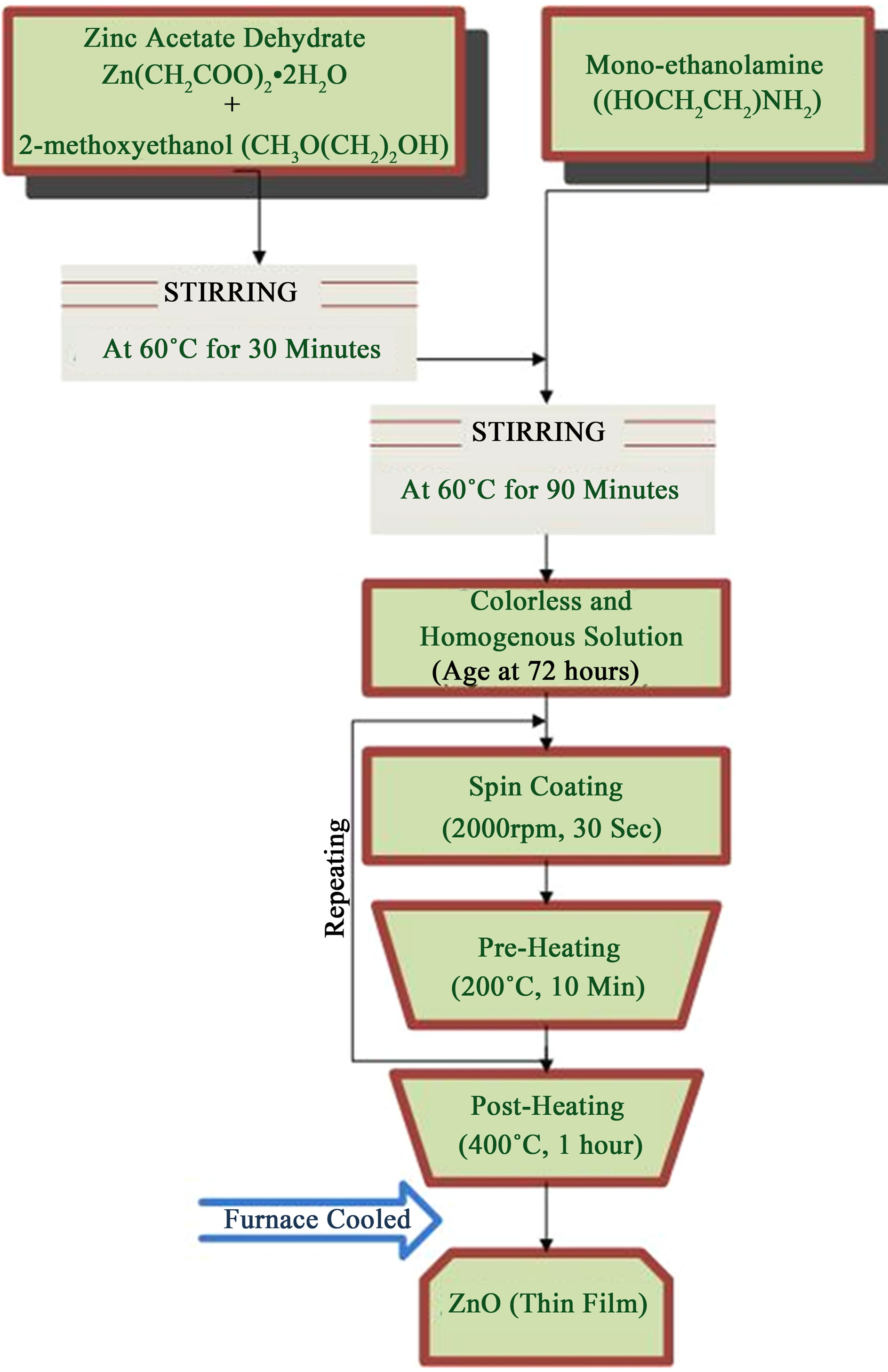
Figure 1. The flow chart showing the procedure for preparing ZnO films.
get a stable homogenous solution. The explanation of the formation of ZnO crystals in [28] enlighten that there are two possible ways of describing the growth of ZnO crystal; Aggregation and Ostwald Growth (ripening). As soon as the smallest stable molecular clusters (they may be unit cells) are formed, they rapidly combine to give the next most stable aggregate. The primary aggregates would further rapidly combine to give the next most stable seconddary aggregate and so on. The authors observed that the primary clusters were stable aggregates and would be the result of rapid aggregation rather than a result of Ostwald growth and concluded that the Ostwald mechanism should be considered as only one possible approach to the formation of bulk materials. Tokumoto et al. [29] reported that the formation of ZnO colloidal particles in an alcoholic solvent consists of two stages. During the early stage of phase transformation, small olygomers are continuously formed. At advanced stages, the aggregation of the olygomers leads to crystalline wurtizite, the primary colloidal particles. The primary particles then aggregate and form a third family, the secondary colloidal particles. The growth of the colloidal particles is a stepped, discontinuous process indicating that the predominant mechanism of aggregation is heterogeneous coagulation. This mechanism of formation and growth leads to a hierarchical structure.
3. Results and Discussion
3.1. Structural Analysis of Nanoycrystalline Films
Figure 2 depict the X-ray diffraction (XRD) pattern of the crystal structure and orientation of the nanocrystalline ZnO thin film deposited on glass substrate using spincoating at 2000rpm, pre-heated at 200˚C and annealed in air at 400˚C. From the XRD pattern, one can clearly observe a diffraction peak at 2θ = 34.34˚. Strong preferential growth is observed along c-axis i.e. (002) plane, suggesting that the prepared ZnO nanocrystals have the wurtzite structure. Sumetha Suwanboon [30] proposed a qualitative idea for the formation mechanism of the preferential oriented thin films could be the minimization of the surface free energy of each crystal plane and usually films grows so as to minimize the surface energy. Due to the minimization of surface energy, heterogeneous nucleation readily happens at the interface of film and substrate.
The unit cell “a” and “c” of the polycrystalline ZnO films with (002) orientation are calculated using the Relations (1) and (2):
 (1)
(1)
 (2)
(2)
The values obtained for the unit cell a = 3.013Å and c = 5.218Å are in good agreement with those reported in the JCPDS standard data (Card no. 80-0074). The calculated lattice parameters are given in Table 1.
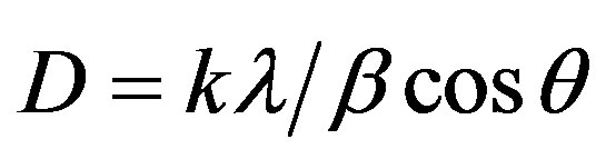
From the XRD spectrum, grain size (D) of the film is calculated using the Debye Scherrer formula [31].
 (3)
(3)
where k is a constant to be taken 0.49 [31] and λ, β, and θ are the X-ray wavelength (=1.5406Ǻ), full width at half maximum (FWHM) and Bragg angle respectively. By inserting the different values from Table 2 in the Scherrer formula grain size of (002) oriented thin film is 16 nm which is same as reported in literature [32].
The dislocation density (δ), which represents the amount of defects in the crystal, is estimated from the following equation:
 (4)
(4)
Strain (ε) of the thin film is determined from the following formula:
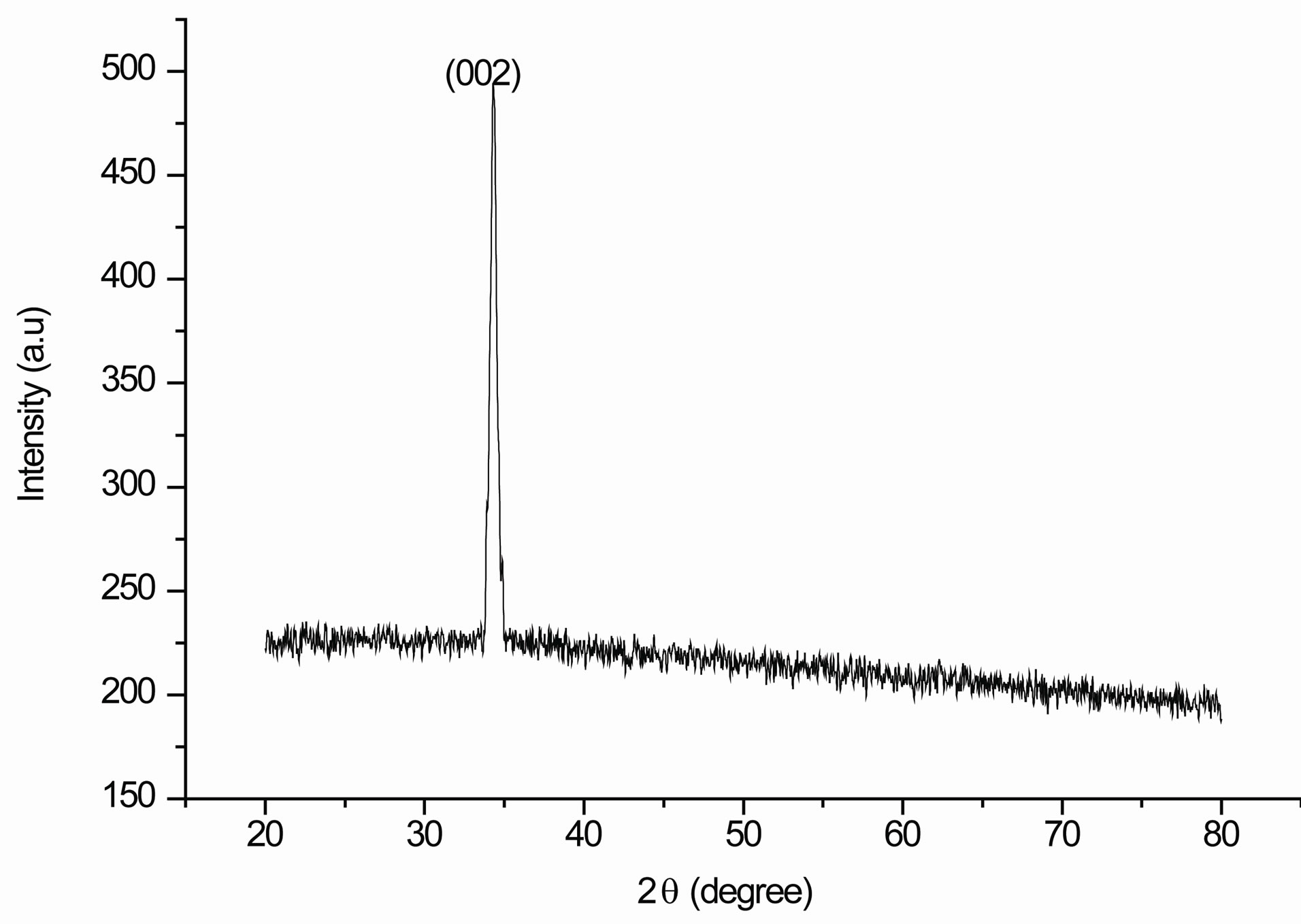
Figure 2. XRD spectrum of the nanocrystalline ZnO thin film.
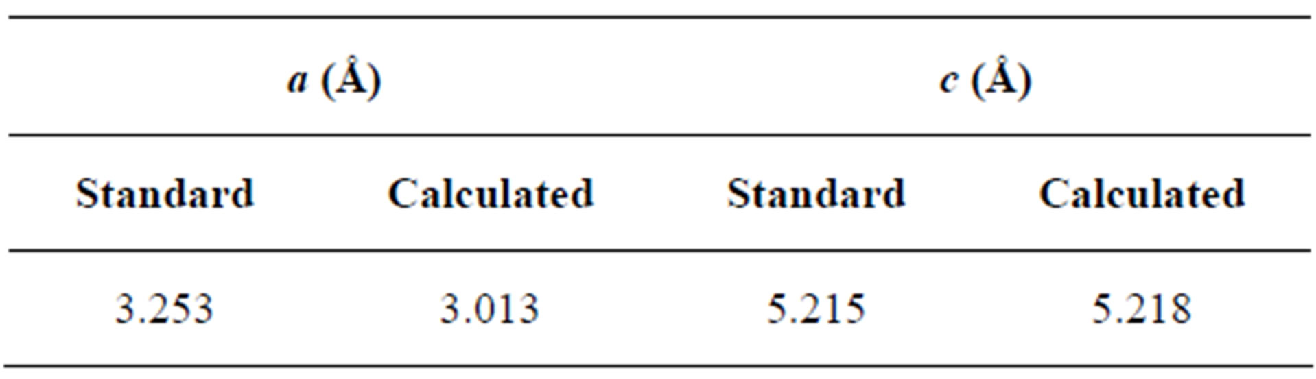
Table 1. Lattice parameters of the ZnO thin film.

Table 2. Structural parameters of thin film.
 (5)
(5)
The calculated structural parameters of the thin film are presented in Table 2.
3.2. Morphological Analysis of Nano-Crystalline Films
The surface topography of thin film is very important tool to investigate microstructure of the films. Scanning Electron Microscopy (SEM) micrograph of ZnO thin film is shown in Figure 3(a) with presence of tightly packed grains. The nanocrystals are regularly distributed on the glass substrate and crystallite size is approximately 16 nm. It can be seen from Figure 3(a) that the small grains made a smooth and transparent surface similar to those observed by other author [32]. The average film thickness is about 266nm. Figure 3(b) delineated energy dispersive scattering (EDS) of the above representative film. It may be seen that besides the characteristics peaks of Zinc and Oxygen, peaks arising out of the substrate Manganese, Gallium, Silicon and Gold are also available. The Gold in ZnO film is from the Gold coating of the samples for SEM analysis.
 (a)
(a)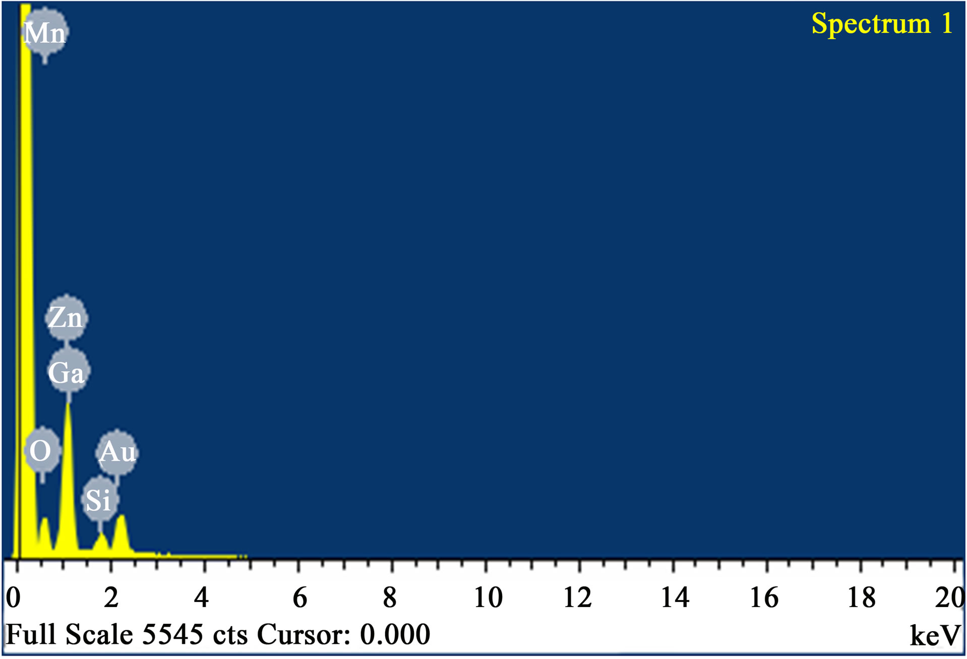 (b)
(b)
Figure 3. (a) SEM image of nanocrystaalline ZnO thin film; (b) EDS image of nanocrystaalline ZnO thin film.
3.3. Optical Properties of Nanocrystalline ZnO Films
Figure 4 shows the optical transmittance spectrum of nanocrystalline ZnO thin films annealed at 400˚C in air for 1 hour using UV-visible region from 200 nm - 800 nm. The transmittance is over 80% in the visible region from 400 nm to 800 nm for all the samples [32]. Sharp absorption edge is located at 380 nm which is due to the fact that the ZnO is a direct band gap semiconductor. The corresponding optical band gap of ZnO thin film is estimated by extrapolation of the linear relationship between (αhυ)2 and hυ according to the equation [33].
αhυ = A (hυ-Eg)1/2(6)
where α is the absorption coefficient, hυ is the photon energy, Eg is the optical band gap and A is a constant. Figure 5 depicts the plot of (αhυ)2 versus photon energy hυ. The values of the direct optical band gap Eg are calculated from the intercept of (αhυ)2 vs hυ curve had also been plotted. The presence of a single slop in the plot suggests that the film has direct and allowed transition. The band gap value of ZnO thin film is found to be 3.296
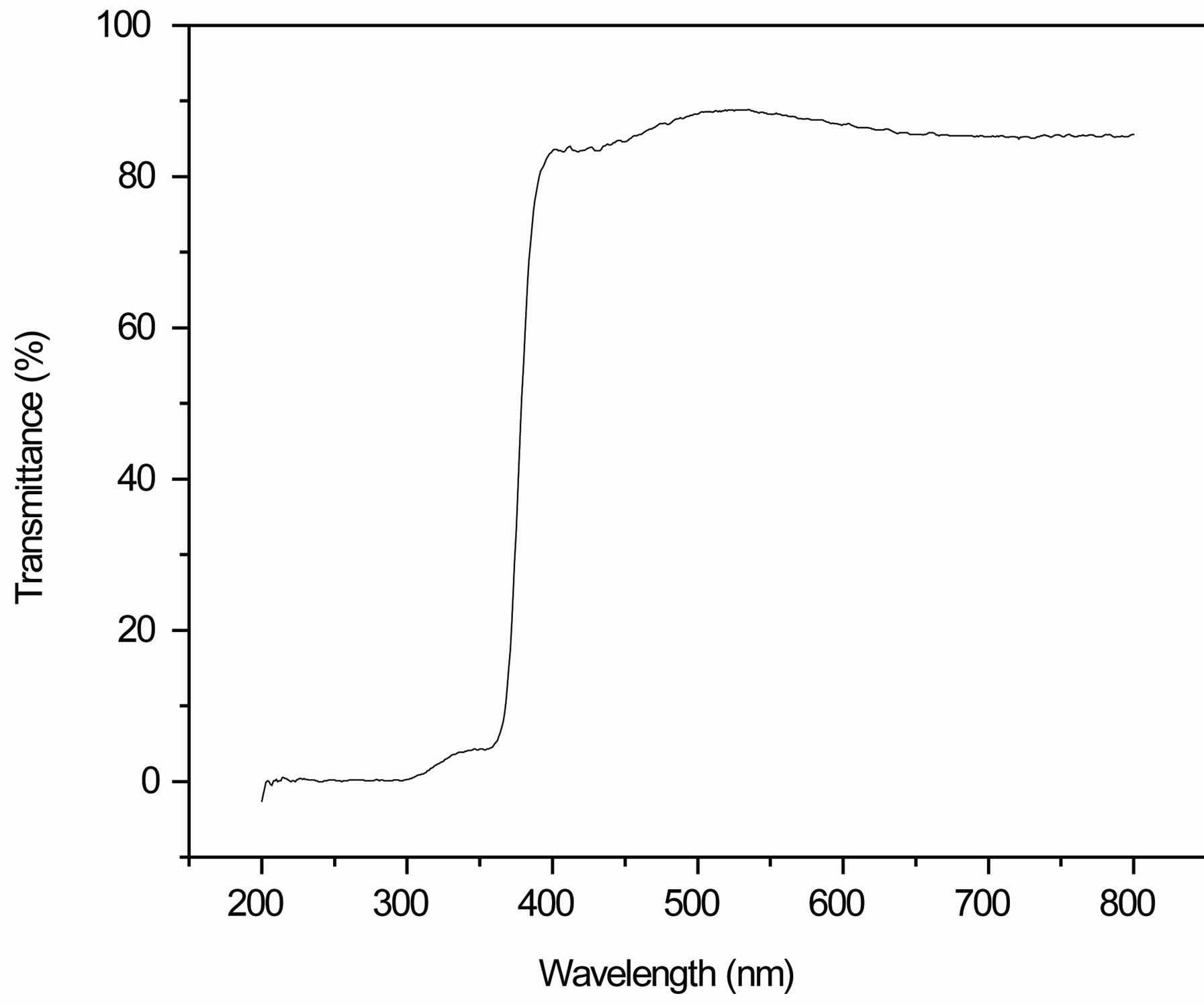
Figure 4. Transmittance spectrum of nanocrystalline ZnO thin film.

Figure 5. Plot of (αhυ)2 vs photon energy hυ of anocrystalline ZnO thin film.
eV which is slightly smaller than that of bulk ZnO (3.37 eV).
This difference is due to the fact that the values of band gap Eg depend on many factors e.g. the granular structure, the nature and concentration of precursors, the structural defects and the crystal structure of the films. Moreover, departures from stoichometry form lattice defects and impurity states. Dinghua Bao et al. [34] reported that the band gap difference between the thin film and crystal is due to the grain boundaries and imperfecttions of the polycrystalline thin films. D. L. Zhang et al. [35] reported that this band gap difference between the film and bulk ZnO is due to the grain boundary, the stress and the interaction potentials between defects and host materials in the films.
4. Conclusion
In this study, we have grown nanocrystalline ZnO thin films on glass substrate by a multi-step sol-gel technique using spin coating. The structural, morphological and optical properties were investigated. The sol-gel method is a relatively simple technique; there are many factors which affect the quality of the films. We have optimized different parameters to obtain a good crystalline structure of ZnO film with intense and sharp peak. According to XRD results, the as-deposited films exhibited a hexagonal wurtzite structure with (002) preferential orientation after annealing at 400˚C in air ambiance for 1 hour. The XRD pattern consists of a single (002) peak which occurred due to ZnO crystals and grows along the c-axis. The grain size and thickness of the films are estimated to be 16 nm and 266 nm. SEM micrograph of ZnO thin film shows that the small grains made a smooth and transparent surface. The optical transmittance is over 80% in the wave length range from 400 nm - 800 nm and the energy band gap is found to be 3.296 eV. Zinc oxide crystallites with preferential (002) orientation are desirables for applications where crystallographic anisotropy is a prerequisite e.g. UV diode lasers, piezoelectric surface acoustic wave or acousto-optic devices.
5. Acknowledgements
This work was partially sponsored by National Natural Science Foundation of China under Grant No. 50942001 and 50975301, and the Third Stage of “211” Innovative Talent Training Project (No. S-09109) of Chongqing University.
REFERENCES
- S. Chakrabarti and B. K. Dutta, “Photocatalytic Degradation of Model Textile Dyes in Wastewater Using ZnO as Semiconductor Catalyst,” Journal of Hazardous Materials, Vol. 112, No. 3, 2004, pp. 269-278.
- S. T. Shishiyanu, T. S. Shishiyanu and O. I. Lupen, “Sensing Characteristics of Tin-Doped ZnO Thin Films as NO2 Gas Sensor,” Sensors and Actuators B: Chemical, Vol. 107, No. 1, 2005, pp. 379-386. doi:10.1016/j.snb.2004.10.030
- E. Suvaci and I. O. Ozer, “Processing of Textured Zinc Oxide Varistors via Templated Grain Growth,” Journal of the European Ceramic Society, Vol. 25, No. 9, 2005, pp. 1663-1673. doi:10.1016/j.jeurceramsoc.2004.05.026
- N. Saito, H. Haneda, T. Sekiguchi, N. Ohashi, I. Sakaguchi and K. Koumoto, “Low-Temperature Fabrication of Light-Emitting Zinc Oxide Micropatterns Using Self-Assembled Monolayers,” Advanced Materials, Vol. 14, No. 6, 2002, pp. 418-421. doi:10.1002/1521-4095(20020318)14:6<418::AID-ADMA418>3.0.CO;2-K
- T. Meron and G. Markovich, “Ferromagnetism in Colloidal Mn2+-Doped ZnO Nanocrystals,” Journal of Physical Chemistry B, Vol. 109, No. 43, 2005, pp. 20232-20236. doi:10.1021/jp0539775
- M. H. Huang, S. Mao, H. Feick, H. Yan, Y. Wu, H. Kind, E. Weber, R. Russo and P. Yang, “Room-Temperature Ultraviolet Nanowire Nanolasers,” Science, Vol. 292, No. 5523, 2001, pp. 1897-1899. doi:10.1126/science.1060367
- J. B. Webb, D. F. Williams and M. Buchanan, “Transparent and Highly Conductive Films of ZnO Prepared by RF Reactive Magnetron Sputtering,” Applied Physics Letters, Vol. 39, No. 8, 1981, pp. 640-642. doi:10.1063/1.92815
- S. J. Kang, J. Y. Choi, D. H. Chang and Y. S. Yoon, “A Study on the Growth and Piezoelectric Characteristics of ZnO Thin Film Using a RF Magnetron Sputtering Method,” Journal of Korean Physics Society, Vol. 47, No. 93, 2005, pp. S589-S594.
- S. Major, S. Kumar, M. Bhatnagar and K. L. Chopra, “Effect of Hydrogen Plasma Treatment on Transparent Conducting Oxides,” Applied Physics Letters, Vol. 49, No. 7, 1986, pp. 394-396. doi:10.1063/1.97598
- N. G. Dhere, “Present Status and Future Prospects of CIGSS Thin Film Solar Cells,” Solar Energy Materials and Solar Cells, Vol. 90, No. 15, 2006, pp. 2181-2190. doi:10.1016/j.solmat.2006.02.018
- N. F. Cooray, et al., “Large Area ZnO Films Optimized for Graded Band-Gap Cu(InGa)Se2-Based Thin-Film MiniModules,” Solar Energy Materials and Solar Cells, Vol. 49, No. 1-4, 1997, pp. 291-297. doi:10.1016/S0927-0248(97)00055-X
- Y. Hagiwara, T. Nakada and A. Kunioka, “Improved Jsc in CIGS Thin Film Solar Cells Using a Transparent Conducting ZnO:B Window Layer,” Solar Energy Materials and Solar Cells, Vol. 67, No. 1-4, 2001, pp. 267- 271. doi:10.1016/S0927-0248(00)00291-9
- O. Kluth, B. Rech, L. Houben, et al. “Texture Etched ZnO:Al Coated Glass Substrates for Silicon Based Thin Film Solar Cells,” Thin Solid Films, Vol. 351, No. 1-2, 1999, pp. 247-253. doi:10.1016/S0040-6090(99)00085-1
- J. Mueller, B. Rech, J. Springer and M. Vanecek, “TCO and Light Trapping in Silicon Thin Film Solar Cells,” Solar Energy, Vol. 77, No. 6, 2004, pp. 917-930. doi:10.1016/j.solener.2004.03.015
- J. Springer, B, Rech, W, Reetz, et al. “Light Trapping and Optical Losses in Microcrystalline Silicon Pin Solar Cells Deposited on Surface-Textured Glass-ZnO Substrates,” Solar Energy Materials and Solar Cells, Vol. 85, 2001, pp. 1-11.
- P. Nunes, D. Costa, E. Furtunato and R. Martins, “Performances Presented by Zinc Oxide Thin Films Deposited by R. F. Magnetron Sputtering,” Vacuum, Vol. 64, No. 3- 4, 2002, pp. 293-297. doi:10.1016/S0042-207X(01)00323-2
- M. Krunks and E. Mellikov, “Zinc Oxide Thin Films by the Spray Pyrolysis Method,” Thin Solid Film, Vol. 270, No. 1-2, 1995, pp. 33-36. doi:10.1016/0040-6090(95)06893-7
- K. Tominaga, T. Takao, A. Fukushima, T. Moriga and I. Nakabayashi, “Amorphous ZnO-In2O3 Transparent Conductive Films by Simultaneous Sputtering Method of ZnO and In2O3 Targets,” Vacuum, Vol. 66, No. 3-4, 2002, pp. 505-509. doi:10.1016/S0042-207X(02)00123-9
- D. C. Look, D. C. Reynolds, C. W. Litton, R. L. Jones, D. B. Eason and G. Gantwell, “Characterization of Homoepitaxial p-Type ZnO Grown by Molecular Beam Epitaxy,” Applied Physics Letters, Vol. 81, No. 10, 2002, pp. 1830-1832. doi:10.1063/1.1504875
- N. Naghavi, C. Marcel, L. Dupont, A. Rougier, J. B. Leriche and C. Guery, “Structural and Physical Characterisation Oftransparent Conducting Pulsed Laser Deposited In2O3-ZnO Thin Films,” Journal of Materials Chemistry, Vol. 10, No. 10, 2000, pp. 2315-2319. doi:10.1039/b002094j
- Y. Natsume and H. Sakata, “Electrical and Optical Properties of Zinc Oxide Films Post-Annealed in H2 after Fabrication by Sol-Gel Process,” Materials Chemistry and Physics, Vol. 78, No. 1, 2002, pp. 170-176. doi:10.1016/S0254-0584(02)00314-0
- E. J. Luna-Arredondo, A. Maldonado, R. Asomoza, D. R. Acosta, M. A. Melendez-Lira and M. de la L. Olvera, “Indium-Doped ZnO Thin Films Deposited by the SolGel Technique,” Thin Solid Films, Vol. 490, No. 2, 2005, pp. 132-136. doi:10.1016/j.tsf.2005.04.043
- N. R. S. Farley, C. R. Staddon, L. X. Zhao, K. W. Edmunds, B. L. Gallagher and D. H. Gregory, “Sol-Gel Formation of Ordered Nanostructured Doped ZnO Films,” Journal of Materials Chemistry, Vol. 14, No. 7, 2004, pp. 1087-1092. doi:10.1039/b313271d
- L. J. Mandalapu, F. X. Xiu, Z. Yang, D. T. Zhao and J. L. Liu, “p-Type Behavior from Sb-Doped ZnO Heterojunction Photodiodes,” Applied Physics Letters, Vol. 88, No. 11, 2006, pp. 112108-112110. doi:10.1063/1.2186516
- N. Viart, M. Richard-Plouet, D. Muller and G. Pourroy, “Synthesis and Characterization of Co/ZnO Nanocomposites: Towards New Perspectives Offered by Metal/Piezoelectric Composite Materials,” Thin Solid Films, Vol. 437, No. 1-2, 2003, pp. 1-9. doi:10.1016/S0040-6090(02)00785-X
- M. Ohyama, H. Kozuka and T. Yoko, “Sol-Gel Preparation of ZnO Films with Extremely Preferred Orientation along (002) Plane from Zinc Acetate Solution,” Thin Solid Films, Vol. 306, No. 1, 1997, pp. 78-85. doi:10.1016/S0040-6090(97)00231-9
- E. J. Gonzalez, J. A. S. Urueta and R. S. Parra, “Optical and Electrical Characteristics of Aluminum-Doped ZnO Thin Films Prepared by Sol-Gel Technique,” Journal of Crystal Growth, Vol. 192, No. 3-4, 1998, pp. 430-438. doi:10.1016/S0022-0248(98)00422-9
- L. Spanhel and M. A. Anderson, “Research Article Semiconductor Clusters in the Sol-Gel Process: Quantized Aggregation, Gelation, and Crystal Growth in Concentrated Zinc Oxide Colloids,” Journal of the American Chemical Society, Vol. 113, No. 8, 1991, pp. 2826-2833. doi:10.1021/ja00008a004
- M. S. Tokumoto, S. H. Pulcinelli, C. V. Santilli and A. F. Craievich, “SAXS Study of the Kinetics of Formation of ZnO Colloidal Suspensions,” Journal of Non-Crystalline Solids, Vol. 247, No. 1-3, 1999, pp. 176-182. doi:10.1016/S0022-3093(99)00059-9
- S. Suwanboon, “The Properties of Nanostructured ZnO Thin Film via Sol-Gel Coating,” Naresuan University Journal, Vol. 16, No. 2, 2008, pp. 173-180.
- Z. R. Khan, M. Zulfequar and M. S. Khan, “Optical and Structural Properties of Thermally Evaporated Cadmium Sulphide Thin Films on Silicon (100) Wafers,” Materials Science and Engineering: B, Vol. 174, No. 1-3, 2010, pp. 145-149. doi:10.1016/j.mseb.2010.03.006
- V. Kumari, V. Kumar and B. P. Malik, D. Mohan and R. M. Mehra, “Laser Induced Nonlinear Optical Properties of Zinc Oxide Thin Film Prepared,” Journal of Nanoand Electronic Physics, Vol. 3, No. 1, 2011, pp. 601-609.
- M. Caglar, S. Ilican and Y. Caglar, “Influence of Dopant Concentration on the Optical Properties of ZnO: In Films by Sol-Gel Method,” Thin Solid Films, Vol. 517, No. 17, 2009, pp. 5023-5028.
- D. Bao, H. Gu and A. Kuang, “Sol-Gel Derived C-Axis Oriented ZnO Thin Films,” Thin Solid Films, Vol. 312, No. 1-2, 1998, pp. 37-39.
- D. L. Zhang, J. B. Zhang, Q. M. Wu and X. S. Miao, “Microstructure, Morphology, and Ultraviolet Emission of Zinc Oxide Nanopolycrystalline Films by the Modified Successive Ionic Layer Adsorption and Reaction Method,” Journal of the American Ceramic Society, Vol. 93, No. 10, 2010, pp. 3284-3290.
NOTES
*Corresponding author.