World Journal of Nano Science and Engineering
Vol.4 No.2(2014), Article
ID:45745,8
pages
DOI:10.4236/wjnse.2014.42007
Static Crack Propagation of Carbon Nanotube through Non-Bonded Interface of Nanocomposites
Khondaker Sakil Ahmed*, Ang Kok Keng
Department of Civil & Environmental Engineering, National University of Singapore, Singapore City, Singapore
Email: *sakil0104@gmail.com, ceeksa@nus.edu.sg
Copyright © 2014 by authors and Scientific Research Publishing Inc.
This work is licensed under the Creative Commons Attribution International License (CC BY).
http://creativecommons.org/licenses/by/4.0/


Received 22 November 2013; revised 23 January 2014; accepted 30 January 2014
ABSTRACT
This study presents an analytical shear-lag model to illustrate the interface crack propagation of carbon nanotube (CNT) reinforced polymer-matrix composites (PMCs) using representative volume element (RVE). In the model, a 3D cylindrical RVE is picked to present the nanocomposite in which CNT/polymer chemically non-bonded interface is taken into consideration. In the nonbonded interface, the stress transfer of CNT is generally considered to be controlled by the combined contribution of mechanical interlocking, thermal residual stress, Poisson’s contraction and van der Waals (vdW) interaction. Since CNT/matrix interface becomes debonded due to crack propagation, vdW interaction which is a function of relative radial displacement of the CNT/matrix interface makes the modeling of the interface tricky and challenging. In order to solve this complexity, an iterative approach is proposed to calculate the vdW interaction for debonded CNT/ matrix interface accurately. The analytical results aim to obtain the characteristics load displacement relationship in static crack propagation for CNT reinforced PMCs.
Keywords:Polymer-Matrix Composites (PMCs), Interface, Computational Modelling, Crack Propagation

1. Introduction
Carbon nanotubes have exceptional mechanical properties such as extremely high strength and stiffness and they have already been considered as superior candidate of reinforcement for mechanically high strength, lightweight and smart nanocomposite [1] -[6] . However, huge strength difference between CNT and most other potential polymers that significantly influence composite behaviour makes the CNT/matrix interface more critical [7] -[13] . The key controlling factors at the CNT/polymer non-bonded interface are identified to be mechanical interlocking (friction), thermal residual stress and non-covalent bonding like van der Waals (vdW) interactions [14] -[16] .
Evaluating the static crack propagation in nanocomposite between nanotube and matrix at nanoscale is one of many difficult tasks. Very few works have been carried out on investigating the damage behavior, interfacial sliding or crack propagation of CNT in polymer matrix. This can be attributed to the fact that experimental investigation on nanotube crack propagation is quite impossible due to the difficulties arising in gripping, manipulation and stress, strain measurement at the nanoscale. Analytical studies are used to be a shed of light on nanoscale behavior and to obtain information that may not be easily obtained from experiments.
Classical shear-lag model is widely used to obtain interface characteristics for fibre reinforced composite since 1950s. Recently, some researchers have extended the application of the shear-lag model for nanotube as well as nanorope (several CNT as bundle) reinforced composite using representative volume element (RVE) concept [14] [17] -[21] . Though there are some studies based on the interface fracture toughness to investigate interface cracking for fiber reinforced composite using shear-lag model, most of them consider the case of interface cracking of perfectly bonded interface to be debonded interface. However, perfect bonding at the interface is not always common and can be achieved only by the creation of chemical bonding at the interface. The creation of chemical bonding is sometimes not only costly but also difficult to achieve uniformly over the interface. Ang and Ahmed [22] proposed an improved shear-lag model that can be largely used to obtain stress transfer mechanism for chemically non-bonded interface. As far with the author’s knowledge, there is no study in the literature that investigates the crack propagation for the chemically non-bonded interface considering vdW interaction.
This study aims to extend their previous study [22] to investigate the interface crack propagation of CNT in polymer Nanocomposites. The key target of this study is to obtain the stress displacement relationship as static crack propagates though the chemically non-bonded CNT/matrix interface. This study can be useful to illustrate the static crack propagation of CNT that may be used as preliminary step before experimental investigation.
2. Analytical Model for Static Crack Propagation
An analytical shear-lag model is proposed to investigate the static crack propagation for non-bonded CNT/matrix interface, as shown in Figure 1. The figure includes a 3D representative volume element that comprises a CNT of length 2L and outer diameter of 2a. Generally, the maximum interfacial shear stress of CNT is observed
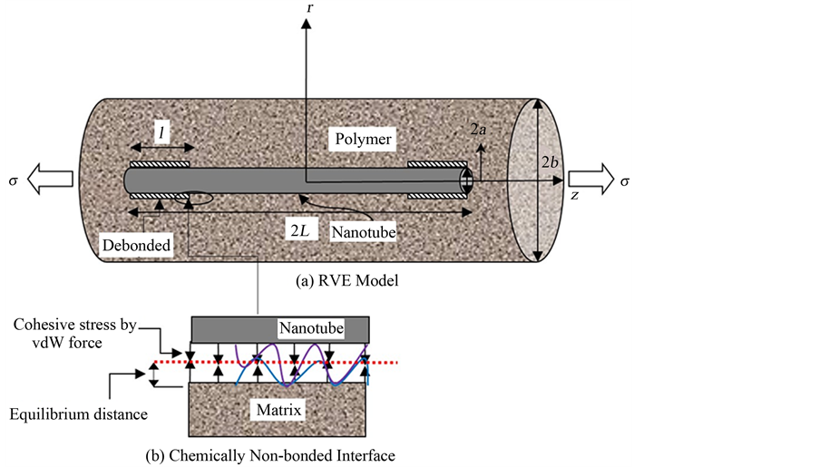
Figure 1. Model for static crack propagation of nanotube reinforced composite.
to be near at the end of the nanotube and hence it is considered that debonding starts from the end rather than the center of the RVE.
Since the model is symmetric with respect to its center, it is assumed that the crack will propagate in similar pattern with equal debonded length for both sides of the nanotube. The length of the debonded interface is denoted by l. σ is the applied stress at the remote end of the RVE. The other parameters of the nanocomposite that has been used in the shear-lag model are presented in Figure 1.
Similar to our previous study [20] , this study also considers that the stress is transferred through matrix to CNT by the combined contribution of thermal residual stress, Poisson’s contraction and vdW interactions. The interface debonding crack propagation criterion used in this study is based on fracture mechanics where the strain energy release rate against the debonded length is equated to the interface fracture toughness, Git
 (1)
(1)
Ute is the sum of the total strain energy stored in the frictionally bonded region; 0 < z < (L − l) and debonded region, (L − l) < z < L. Therefore, total strain energy may be obtained from the algebraic sum of the strain energy at the frictionally bonded interface Ufb and frictionally debonded interface Ufd,
 (2)
(2)
The length of the debonded region increases as the crack propagation proceeds. The strain energy due to frictionally bonded interface (Ufb) and debonded interface (Ufb) can be obtained by integrating over their corresponding stress components over the volume of the respective regions as given in Equation (3a) and (3b).
 (3a)
(3a)
 (3b)
(3b)
2.1. Solutions for Frictionally Bonded Interface 0 < z < (l ‒ L)
Since this study considers chemically non-bonded interface, the stress transfer of CNT through such type of interface is determined by the combined contribution of mechanical interlocking (i.e. frictionally bonded), thermal residual stress and vdW interaction. The solutions for axial stress of CNT , matrix
  and shear stress
 at any radial location of the matrix for the such type of frictionally bonded (chemically non-bonded) interface are recalled from the improved shear-lag model proposed by Ang and Ahmed (2013) [22] .
 (4)
(4)
 (5)
(5)
 (6)
(6)
where
 (7a)
(7a)
 (7b)
(7b)
 (7c)
(7c)
 (7d)
(7d)
 (7e)
(7e)
 (7f)
(7f)
 (7g)
(7g)
 (7h)
(7h)
 (7i)
(7i)
 (7j)
(7j)
By the Substitution of Equations (4)-(6) in the Equation (3a) and then double integration over the corresponding region strain energy at the frictionally bonded interface can be obtained.
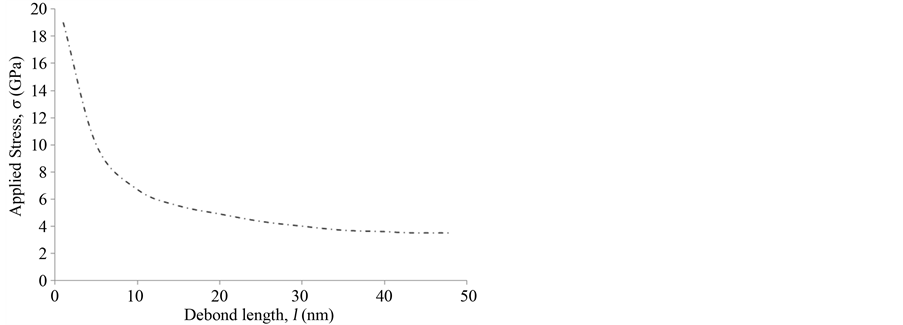
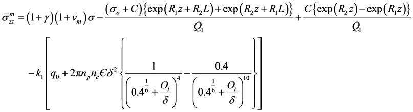
2.2. Solutions for Frictionally Debonded Interface (L ‒ l) < z The template Previously, Ahmed and Ang [23] proposed a shear-lag model for debonded interface to investigate the load transfer mechanism of CNT in polymer composite. The model is capable to provide analytical solutions for the axial stress of CNT in which Again by the Substitution of Equations (8)-(10) in the Equation (3b) and then double integration over the corresponding region strain energy at the frictionally bonded interface can be obtained. After replacing the total strain energy in Equation (1) and differentiating with respect to debonded length (l) and then after rearranging, the required stress (σ) to cause interface cracking may be derived as follows in which 3. Results & Discussions When the stress is applied to the nanocomposite and reaches beyond the allowable limit of interfacial shear stress, the interface starts to become debonded as well as the static crack propagation enhances. Based on the analytical solution stated in Equation (12), analytical result for static crack propagation in nanocomposite can be obtained. However, the solution is not straight forward because the debonded interface does not follow strain compatibility which results in relative radial displacement between the CNT and polymer matrix. The vdW interaction which is a function of initial interface displacement and relative radial displacement due to the application of load varies along the length of the debonded region of the CNT/matrix interface. In this investigation of interface crack propagation along the frictionally bonded interface, the variation of the van der Wall interaction due to the relative radial displacement is accounted in estimating the stress displacement relationship and hence an iterative approach has been used to calculate the vdW interaction for debonded CNT/matrix interface. The available experimental data that has been used in this study are presented in Table1 Since the analytical model for static crack propagation is axisymmetric, only right hand side of the crack propagation is presented. The characteristics curve for the required applied stress at the remote end of RVE corresponding to the debond length of the embedded nanotube is presented in Figure 2. It can be seen from the figure that the maximum and minimum stress required to propagate debonding are found to be approximately 19 GPa and 3.75 GPa, respectively when debonding length is nearly zero and complete debonding, respectively. The figure shows that with the increase of debond length, initially the required applied stress for interface crack propagation sharply decreases before reaching a nearly constant region. For example if the debond length is 25%, the required applied stress decreases by 70% of that required to debond a completely bonded interface. The required stress to debond the last 60% of the embedded length is only 20% of initial requirement. It is interesting to note that after complete debonding has occurred, the CNT is found to be capable of carrying further stress. This happens due to the fact that after debonding, shear stress due to thermal residual stress and van der Waal interaction will be still active at the debonded interface. In another comparison, it is observed Figure 2. Characteristics curve for interface cracking stress corresponding to debond length. Table 1. The definition and value of the parameters. that the stress carrying ability of completely debonded interface is nearly 20% of the stress required to debond the bonded interface. 4. Conclusions A shear-lag model has also been proposed for investigating the interfacial static crack propagation of CNT reinforced composite. Using the proposed model, closed form analytical solution for required cracking stress corresponding to debonded length is derived. Subsequently, analytical result is presented for static crack propagation with respect to the application of uniform stress. The stress required in causing interface cracking is found to decrease as the debonding length increases. The result also revealed that CNT fiber can take stress even after complete debonding which is mainly due to thermal residual stress and van der Waals interactions. The characteristics curve also shows that after completing debonding has occurred, the CNT is found to be capable of carrying further stress. One of the key achievements of this study is that the proposed shear-lag model is capable of incorporating the cohesive stress caused by vdW interaction together with the other components. It should be noted that the proposed model is a useful alternative to other more complicated methods such as molecular mechanics and molecular dynamics simulations, which are not only time consuming but also costly. References NOTES *Corresponding author. , matrix
  and shear stress
  of the matrix for the debonded interface as presented in Ahmed and Ang [23] . The solutions are recalled as given in Equations (8)-(10)
 (8)
(8) (9)
(9) (10)
(10) (11)
(11) (12)
(12) (13a)
(13a) (13b)
(13b) (13c)
(13c) (13d)
(13d)