World Journal of Nano Science and Engineering
Vol.3 No.4(2013), Article ID:40507,33 pages DOI:10.4236/wjnse.2013.34017
Carbonaceous Nanostructured Support Materials for Low Temperature Fuel Cell Electrocatalysts—A Review
1Department of Chemical Engineering, Engineering Faculty, Ferdowsi University of Mashhad, Mashhad, Iran
2Nanotechnology Research Institute, Noshirvani University of Technology, Babol, Iran
3Department of Chemical Engineering, Engineering Faculty, Noshirvani University of Technology, Babol, Iran
Email: *m_yaldagard@yahoo.com, *mjahan@nit.ac.ir
Copyright © 2013 Maryam Yaldagard et al. This is an open access article distributed under the Creative Commons Attribution License, which permits unrestricted use, distribution, and reproduction in any medium, provided the original work is properly cited.
Received August 5, 2013; revised September 16, 2013; accepted September 23, 2013
Keywords: Low Temperature Fuel cell; PEMFC; DMFC; Pt-based Electrocatalyst; Nanostructured-supports; Durability/Stability
ABSTRACT
Highly-dispersed platinum and platinum-based catalysts on a conductive support are commonly used as electrode materials in low-temperature fuel cells, particularly the hydrogen PEMFC and the direct methanol PEMFC. The performance and durability/stability of these catalysts strongly depend on the characteristics of the support. Catalysts supported on high surface area carbon black are widely used in low-temperature fuel cells. However, the corrosion of carbon black has been recognized as one of major causes of performance degradation and durability issues of low-temperature fuel cells under high-potential conditions. So the need for alternative supports with outstanding physical and mechanical properties to carry out the successful reaction in catalyst layer and give a longer lifetime for the electrocatalysts is inevitable. The emergence of nanotechnology and development of nanostructure materials in recent years has opened up new avenues of materials development for low-temperature fuel cells. This paper presents the performance with a variety of carbon-based nanostructured materials such as carbon nanotubes (CNT), carbon nanofibers (CNF), carbon aerogels, nanoplates of graphene, etc. So the present paper provides an overview of these nanostructured materials as low-temperature fuel cell catalyst supports. The improved characteristics of the nanostructured supports with respect to commercially used carbon black (Vulcan XC-72) and their effect on the electrochemical activity are highlighted. Additionally, it reviews the literature on the synthesis of nanostructured-supported Pt electrocatalysts for proton exchange membrane (PEM) fuel cell catalyst loading reducing through the improvement of catalyst utilization and activity. The features of each synthetic method were also discussed based on the morphology of the synthesized catalysts.
1. Introduction
In recent years, the concept of green energy has attracted considerable attention. The aim of green energy is to explore techniques and methodologies that reduce or eliminate the generation of products or byproducts that are hazardous to human health or the environment. Nowadays, green energy is becoming one of the main goals of designing new processes and reactions in the emerging areas of nanoscience and nanotechnology. Fuel cells are electrochemical conversion devices used for power generation in portable, stationary/residential and transportation applications. As a “green/clean” electric power sourcefuel cells can be used to power vehicles, back-up the power supply for electric devices, and store electricity in power stations by converting water into hydrogen and oxygen during off-peak hours. The only by-products are water and heat. Among various types of fuel cells, proton exchange membrane fuel cells (also called polymer electrolyte membrane fuel cell, PEMFCs) have been considered to be a promising energy source because they offer a highly efficient, low operation temperature (below 100˚C), higher power density, rapid start-up/shut-down, low weight, compactness, potential for low cost and volume, long stack life, suitability for discontinuous operation and environment-friendly technology for energy conversion without the Carnot limitations of combustion engines. Although great progress has been made in the last several decades in the research and development of PEM fuel cells, several technical challenges should be overcome for wide-scale commercialization of PEMFCs. These challenges include reducing the cost of component, optimizing the utilization of electrocatalyst at all current densities, improving the performance and durability/stability of the membrane electrode assembly (MEA), the crucial part of the fuel cell system. As the key component in PEMFC, the electrocatalyst layer is the place where the electrochemical reactions take place and the electrical energy is produced, exhibiting a great influence on the total performance and durability. The main processes that occur in the catalyst layer include mass transport, interfacial reactions at electrochemically active sites, proton transport in the electrolyte phase, and electron conduction in the electronic phase. The PEM fuel cell MEA utilizes precious metal catalyst (such as Pt or Pt alloy) dispersed on support. These catalysts are estimated to contribute to as much as 50% of total fuel cell cost. It was emphasized that in order to reach the DOE (department of energy) cost reduction objects, among other component cost reductions, the current state of the art platinum loading (~0.4 mg/cm2) of PEM fuel cell electrodes, the total Pt catalyst loading in a MEA must be reduced to levels lower than 0.1 mg/cm2 to come across the target for commercialization [1]. Similarly, durability targets for these applications have not been mentioned for catalysts, but MEAs are expected to endure for >40,000 and 3000 hours for stationary and portable applications respectively, with low degradation rates.
Several strategies have been explored with the purpose of reducing the cost and increase the performance of a fuel cell. These active approaches toward the reduction of Pt usage in PEMFC catalyst can generally be listed as:
1) Reducing Pt usage by alloying with other transition metals (either as bimetallic or ternary catalyst systems) and non-noble electrocatalysts.
2) Reducing the Pt loading in fuel cell electrodes by using ultra-low loading catalyst methods.
3) Reducing the electrocatalyst nanoparticle size and improving PPEMFC performance by optimization of operating parameters.
4) Improving electrocatalyst dispersion by using novel fabrication techniques (e.g. The National Research Council of Canada’s Institute for Fuel Cell Innovation (NRCIFCI), Reactive spray deposition technology (RSDT)).
5) Developing MEA fabrication methods to enable better catalyst dispersion and utilization.
6) Improving the performance of carbon-based electrocatalyst support and exploring novel non-carbonaceous electrocatalyst support materials by employing the concept of nanotechnology for increasing the surface area and other properties.
It is very difficult to keep or improve catalyst layer performance when the catalyst loading is reduced. In order to attain that, great effort must be put on Pt utilization and the enhancement of catalyst activity. Two different routes have been explored for enhancing the utilization of platinum catalyst in PEMFCs, either by reducing the particle size of catalyst or by uniforming distribution on the surface of support materials. The prominence of the support materials in fuel cell catalysis is well documented. Typically, the support provides a physical surface for dispersion of small metal particles, which is necessary for accomplishing high surface area. Carbon is commonly used for supporting nanosized electrocatalyst particles in low temperature fuel cells because of its large specific surface area, high electrical conductivity, and pore structures. In spite of the high surface area of the carbon black particle, it has two main problems. Carbon black persuades significant mass transfer limitations due to its dense structure (the pore size and pore distribution of carbon black affects the interaction between Nafion ionomer and the catalyst nanoparticles), resulting failure of launching three-phase boundaries among gas, electrolyte and electrocatalyst which lead to a very low Pt utilization. Additionally, carbon black is known to endure sever electrochemical oxidation, forming surface oxides which react finally to CO2 (C + 2H2O → CO2 + 4H+ + 4e−) at the cathode of the fuel cell. The formation of CO2 or corrosion can be accelerated at lower pH and higher potential, humidity and temperature so the life time of potential electrocatalyst can be reduced by poisoning and sintering. The standard potential for the electrochemical oxidation of carbon to carbon dioxide is 0.207 V vs. RHE at 25˚C [2]. During the start-up/shut-down cycle, the cathode potential of vehicle’s fuel cell because of slow oxygen reduction reaction (ORR) may increase to 1.2 - 1.5 V or even higher, therefore, under such PEMFC cathode operation conditions, carbon corrosion is not only thermodynamically viable due to the high potentials (>1.2 V) and high O2 concentrations, but also kinetically enhanced by the elevated temperatures (50˚C - 90˚C). As carbon black (Vulcan XC-72) corrodes, noble metal nanoparticles (e.g., Pt) on carbon black will isolate from the electrode and possibly combine to larger particles, resulting in Pt surface area loss, which subsequently lowers the durability of PEM fuel cells [3-5]. Accordingly, corrosion of the support may affect the performance of the PEMFC. Therefore, prompted by the thermodynamic instability of carbon, tremendous efforts have been made to identify and develop alternative support materials that show good stability up to voltages of 1.4 - 1.6 V and improve durability and performance.
Nanostructure materials have attracted great interest in recent years because of their exceptional characterization such as high catalytic activity, mechanical and electrical properties, all of which are obtained by obstructing their dimensions. It is well known that the physical, electrochemical, and electronic properties of nanostructured materials are not the same as those of bulk materials. In terms of nanotechnology methodologies towards improving clean energy solution, numerous innovative nanomaterials as catalyst supports for PEMFCs have been actively investigated. In this context, the role of the nanostructure in carbon supports like carbon nanotubes (CNTs), carbon nanofibers (CNFs), carbon aerogels, and nano-plates of grapheme was much highlighted. The main purposes for using nanostructure-supported Pt catalysts are to reduce Pt loading through increasing the catalyst utilization, and improving the catalyst activity and total performance. The higher catalytic activity of Pt and Pt-based catalysts supported on CNTs and CNFs than that of the same catalysts supported on carbon blacks was ascribed to their unique structure and properties such as high surface area, good electronic conductivity and chemical stability [6-10]. Tests carried out in PEM fuel cell conditions indicated that these materials can be more durable and can outlast the lifetime of most widely used Vulcan XC-72.
This review will focus on some recent developments and investigations of nanostructure materials for application as support for preparation of electrocatalyst for MEAs purpose, excluding electrolyte membrane and other parts of fuel cell. The structure, dispersity and morphology of the supported catalysts, which are closely related to utilization and performance, are strongly influenced both by the support property and the method by which Pt nanoparticles can be deposited into the support. In this study, the development of low-temperature fuel cell catalysts in recent years is reviewed, primarily focusing on the two most active areas, i.e. support materials especially supports with tailored nanostructural, surface chemical and electronic properties by employing the concept of nanotechnology and nanoscience in designs and production techniques and Pt-based material deposition approaches.
Considering the recent move of a large variety of the public converging to CNTs, CNFs, and GNFs (graphene nanoplates) related synthesis techniques (also surface modification), we did not discuss the production methods of these materials in the present study, which would have been another useful option if one considers numerous research articles about synthesis and processing techniques of the nanostructure of these materials that have been published in this 10-years span. So where necessary, the reader will be addressed to more specific recent review papers and books. After some simple background information, the structure of each of these materials, the basic deposition techniques of Pt-based metals onto the support materials along with the surface functionalization of these nanostructures, characterization and other features of resulted supported electrocatalyst such as morphology, electrochemical activity as well as electrochemical surface area will be described. Next, it will be continued by describing fabrication processes of MEA fuel cells containing nanostructures. This will be followed by investigating the improvement of utilization of electrocatalyst and performance in single cell measurements. Finally, we give a summary of the stability/durability of the nanostructure-based fuel cell electrodes. Our focus will be on low-temperature fuel cells including only hydrogen and methanol fuelled polymer electrolyte membrane fuel cells (H-PEMFCs [hydrogen fuel cell] and DMFCs) direct methanol fuel cells. The term “PEMFC” has been used often to cover the circumstances where DMFC is also applicable unless specifically mentioned separately.
2. CNT/CNF-Supported Pt Nanoparticles: Characterization and Electrochemical Activity Performance as Anode and Cathode Catalysts for PEM Fuel Cell
The potentiality of using CNT or CNF for fuel cell use, usually as supports for Pt-based particles for PEMFC testing has already been investigated [11-13]. In comparison with the conventional Vulcan XC-72R carbon support which has an electronic conductivity of 4.0 S/cm and specific surface area of 237 m2/g [14], CNT and CNF have significantly higher electronic conductivities of 104 and 103 - 104 S/cm, respectively [15,16] and extremely high specific surface areas of 200 - 900 m2/g [16]. Apart from that, Vulcan XC-72R has a large ratio of micropores which are smaller than 2 nm, while CNT and CNF have no micropores smaller than 2 nm [14]. For Vulcan XC-72R support, the Pt nanoparticles may sink into the micropores, which will reduce the number of three-phase boundary reactive sites, thus reducing the Pt utilization [17,18]. These potential benefits for fuel cell use that have been suggested include higher utilization of active metal due to the lack of smaller porosity and higher corrosion resistance due to the (theoretically) inert surfaces. The main reason for using CNTsand CNFssupported Pt catalysts is to reduce Pt loading through increasing the catalyst utilization, and improving the catalyst activity. Electrocatalysts supported on CNTs or CNFs as electrodes in either PEMFCs or direct methanol fuel cells have been examined extensively and the resulting supported catalysts gave better performance than those supported on commercial carbon black [19]. The attractive features of CNT-based CLs include improved thermal and charge transfer, and maximum exposure of the catalyst sites to the gas reactant through uniform support geometry and parallel alignment. Figure 1 shows

Figure 1. Schematic of the hydrogen fuel cell architecture using an ultra-low Pt loading thin-film Pt/MWNT catalyst layer [20].
the structure of an aligned CNT-based MEA. A mass activity of 250 A/mg Pt at 0.6 μg Pt/cm2 was obtained by Tang et al. [20]. It is well known that the activity of a catalyst depends considerably on the size of the Pt particles and their dispersion configuration over the support structures as well as the particle interactions with the support substrates. It has been found that the optimal dispersion pattern and Pt particle size can be obtained by using an appropriate preparation procedure on an ideal supporting material [21]. So far a large variety of methods like Impregnation, Electrochemical, Colloidal, Ion-exchange, Microwave Heated Polyol, Sputtering, Supercritical Fluid Method have been reported for the deposition of Pt on the surface of CNTs as a support in the literature. All these methods have been successful in yielding Pt nanoparticles but with wide particle size ranges, basically due to agglomeration or inefficient control on the growth of nuclei. However, colloidal process has been well recognized to produce uniform particles with excellent control on nuclei growth and morphology [22]. Different growth control mechanisms and strategies are used in each of the different deposition methods. For example, in the impregnation method, the size of the Pt nanoparticles is controlled by the structure of the support material which acts as the confining intermediate to restrict reaction, diffusion, and aggregation processes. In the colloidal method, the Pt size is controlled either by electrostatic interruption or the addition of a protecting agent, which will adhere onto the surface of Pt nanoparticles. For the ion-exchange method, the surface groups of the support material provide the anchorage sites for the Pt particles and control the dispersion and distribution of the Pt nanoparticles [23]. In this section, some examples of Pt deposition methods will be discussed. Since the pristine surface of CNTs is relatively inert it is impossible to have a high dispersion of Pt nanoparticles with controlled catalyst loading on the surface of support. So surface modification of carbon nanotubes commonly in order to make the surface more hydrophilic and improvement the catalyst support interaction towards an active fuel cell cathode catalyst is compulsory. Essentially, different covalent and non-covalent modification methods have been investigated to functionalize CNTs. Thus, functionalization to introduce surface oxygen groups such as hydroxyl, carboxyl carbonyl and sulfate (using either strong acids like HNO3, H2SO4 or mild acids like citric acid) and other solution like, KMnO4, K2Cr2O7, KOH and H2O2 have been performed on the surface of CNTs. It is believed that these surface functional groups function as metal-anchoring sites to facilitate metal nuclei formation and electrocatalysts deposition [24]. The surface modification of CNTs could also be performed via an electrochemical method [25,26].
Characterization methods that were employed to analyze the CNT and CNF supported Pt catalysts included X-ray diffraction (XRD) to measure average Pt particle size, transmission electron microscopy (TEM) to determine Pt particle size and size distribution, thermal gravimetric analysis (TGA) to determine Pt metal loading and cyclic voltammetry (CV) to obtain information about their electrochemical active surface area (ECSA).
2.1. Deposition Methods of Pt Nanoparticles onto CNTs and Their Morphology
2.1.1. Impregnation Method
Due to its simplicity, impregnation is one of the most commonly used techniques for depositing Pt-based metal on the carbonacouse support for the preparation of the PEM fuel cell electrode. High-surface-area carbon nanotube can be impregnated with catalyst precursors (e.g. ) by mixing the two in an aqueous solution. This is followed by a reduction step which is required to reduce the catalyst precursor to its metallic state. As reduction occurs after the impregnation step, the nature of the support plays a crucial role in controlling particle size. The reduction step can be chemical or electrochemical. Common liquid phase reducing agents are Na2S2O3, sodium borohydride (NaBH4), Na4S2O5, N2H4, and formic acid or hydrazine. H2 is the predominant gas phase reducing agent under higher temperatures. The impregnation technique is a comparatively green method to synthesize catalysts; reduction reactions occur either at low or room temperatures, minimizing energy consumption, and organic solvents are avoided by using aqueous media. Drawbacks of the impregnation technique are related to using liquid solutions as the processing medium. The easily agglomeration of particles in solution has been observed.
Matsumoto and co-workers [18] synthesized Pt nanoparticles supported on CNTs using two Pt precursors; H2PtCl6·6 (H2O) or K2PtCl4. In their research, heated CNTs stirred with Pt precursor in ethylene glycol at 40˚C for 2 h. Then this solution was added into 50 ml of 14 N HNO3 and filtered. A commercial carbon black supported Pt (Pt-CB) electrocatalyst was used as a control to compare the electrode’s performance. TEM images show 2 - 4 nm Pt nanoparticles dispersed on the CNT surfaces. Figure 2(a) shows the TEM image of the HPt-CNT. As can be seen the small dark particles assigned to Pt particles were well dispersed on the CNT surfaces in the TEM image, while Pt particles were deposited locally and agglomerated each other on the KPt-CNT in Figure 2(b).
Cui and coworkers [27] presented a simple and rapid synthesis method (denoted as modified impregnation method, MI) for PtRu/CNTs (MI) and PtRu/C (MI). In their experiments the surface-oxidized CNTs were suspended in deionized water and treated in an ultrasonic bath. Then H2PtCl6 and RuCl3 solution were added dropwise under mechanically agitated conditions for 2 h. Then 5% (v/v) NH3·H2O solution was added to adjust PH of the mixture solution to above 12, therefore  and Ru3+ were precipitated due to the formation of (NH4)2PtCl6 and Ru(OH)3 and the precipitate was adsorbed on CNTs surface. With dropwise addition of NaBH4 solution, (NH4)2PtCl6 and Ru(OH)3 were reduced to Pt and Ru nanoparticles. Consequently, the solution was filtered and washed with hot deionized water until no Cl− was perceived. Finally, the resulting catalysts were dried at 100˚C in a drying oven for 24 h and then transferred to desiccator. The PtRu catalysts supported on CNTs and carbon black were noted Pt-Ru/CNTs (MI) and Pt-Ru/C (MI), respectively. From the transmission electron microscopy (TEM) images it was shown that PtRu particles with small average size (2.7 nm) were uniformly dispersed on carbon supports. Cyclic voltammetry showed that the Pt-Ru/CNTs (MI) catalyst exhibited better methanol oxidation activities than Pt-Ru/C (MI) catalyst and commercial Pt-Ru/C (E-TEK) catalyst (Figure 3).
2.1.2. Electrochemical Method
Electrochemical deposition has been used to deposit Pt and Pt-based nanoparticles on a wide verity of substrates including carbon nanotubes [24] selectively, at desired locations in the substrate through easily controlling the nucleation and growth of the metal nanoparticles. Pulse current, direct current and cyclic voltammetry are utilized to deposit Pt nanoparticles using the electrochemical methods. There are five stages to electrochemical deposition of metals: 1) transport of metal ions in solution to the support surface, 2) electron transfer, 3) formation of metal ad-atoms via adsorption, 4) nucleation and growth, two-or three-dimensional, of metal particles, and 5) growth of the
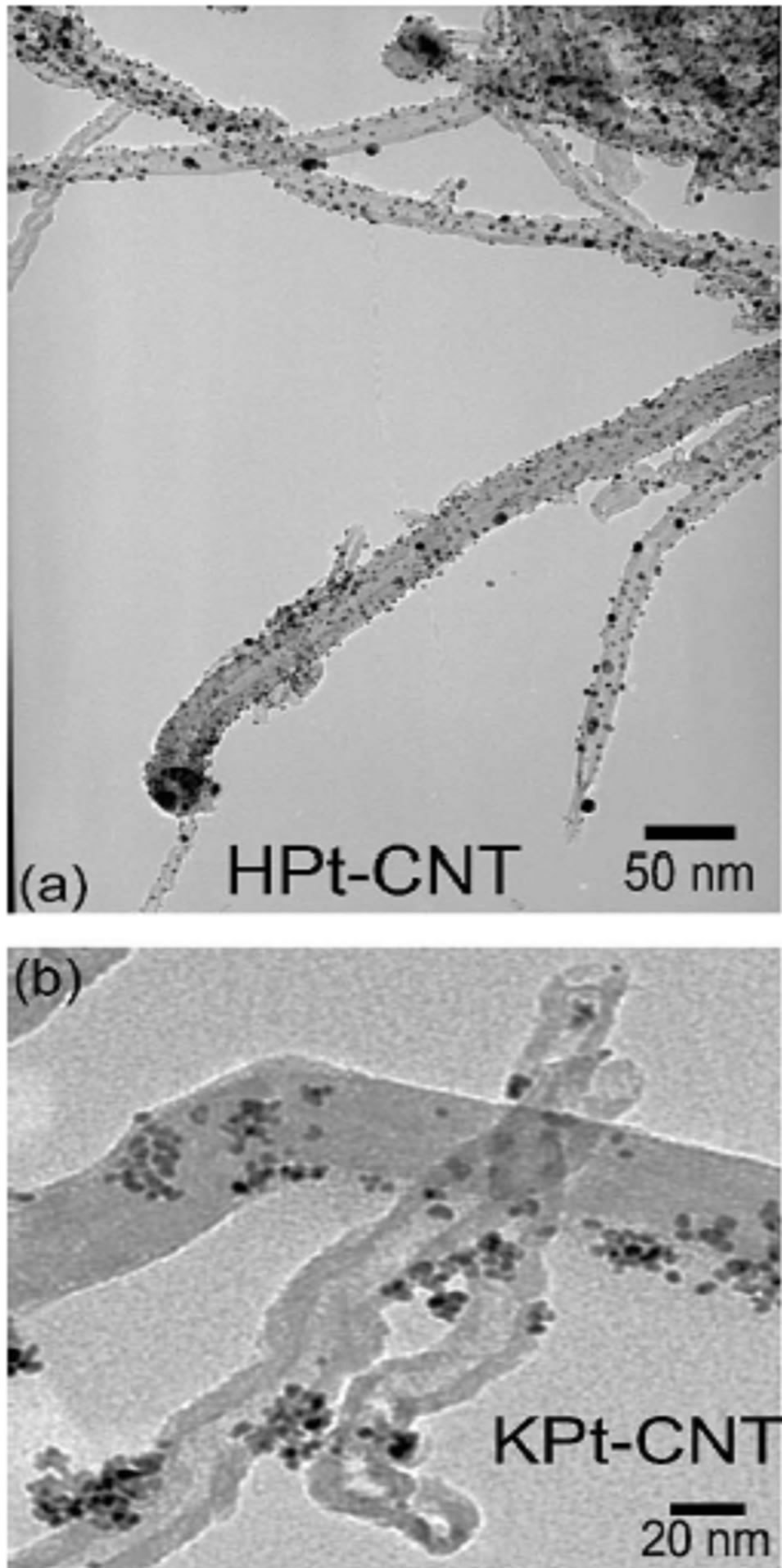
Figure 2. TEM images Pt/CNT catalysts. (a) HPt-CNT; (b) KPt-CNT [18].
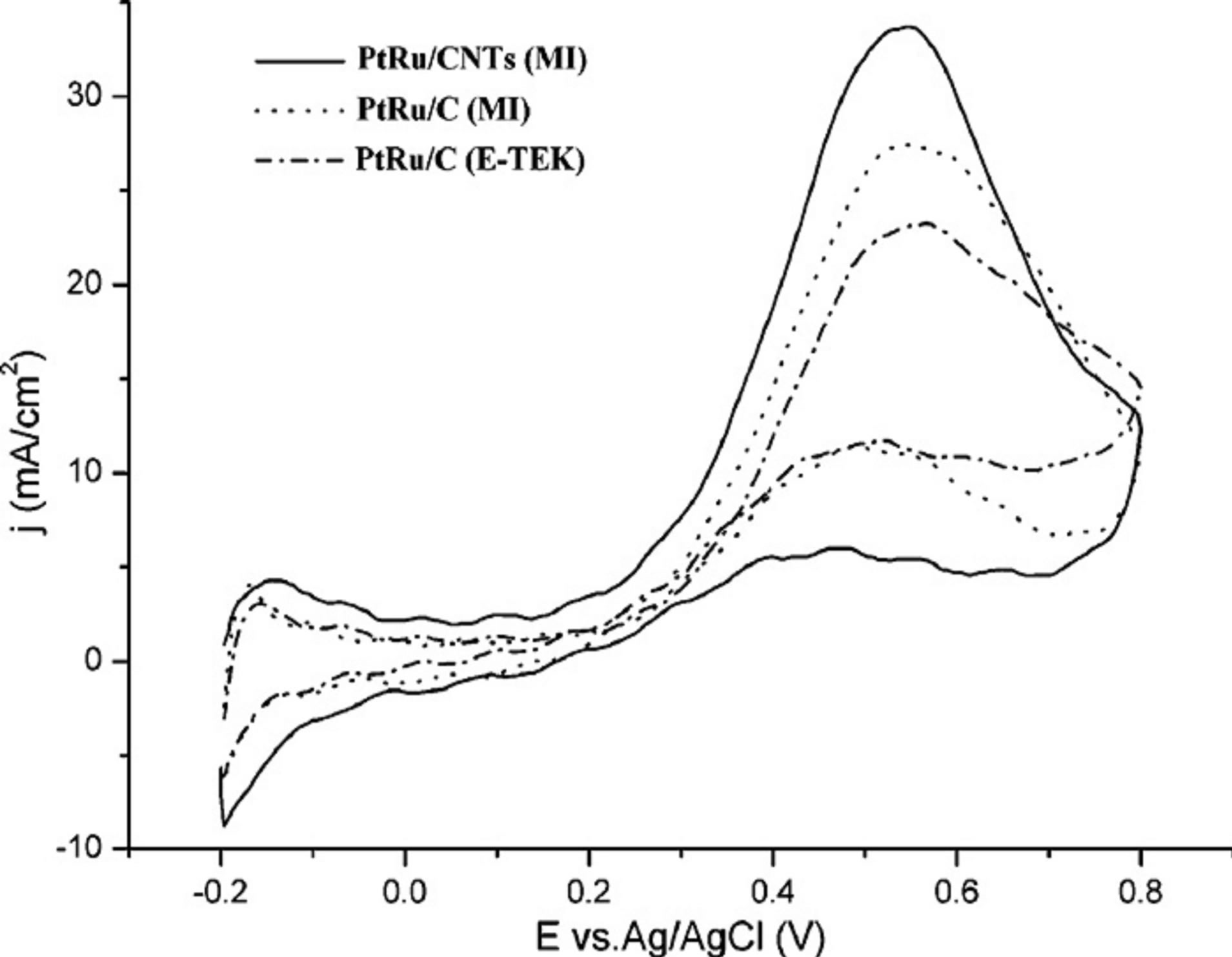
Figure 3. Cyclic voltammograms recorded at 20 mV/s in 1 M CH3OH + 0.5 M H2SO4 solutions at room temperature [27].
three dimensional bulk metal phase. With the electrochemical method, the Pt loading can be reduced ten-fold without sacrificing the cell performance in comparison to the conventional deposition technique [28]. Electrodeposition of Pt nanoparticles on CNTs has recently been reported by several groups. With the vigilant choice of substrate, deposition potential, and growth time, it is possible to deposit nanoparticle with a high degree of monodispersity and narrow particle size distribution [29-31]. Direct potential electrodeposition has been used for the formation of metal nanoparticles that are supported on CNTs. For example, Day and co-workers [32] studied the nucleation and growth mechanisms of the electrodeposition of metals such as Ag and Pt onto CNT s. In their studyPt electrodeposition was performed by stepping the potential from 0 V to −0.4 V (vs Ag/AgCl) for a period of 30 s backing to an open circuit. According the authors this procedure allows the density and size of metal nanoparticles to be controlled by cautious choice of the applied potential and deposition time.
Guo and coworkers [33] described a novel method (potential-step method) for preparation of Pt nanoparticles through molecule-level design, similar to the procedure employed to disperse Ptparticles on other carbon substrates such as highly oriented pyrolytic graphite (HOPG) in the literature [34]. Their TEM images (Figure 4) reveled that the surface of MWNTs was uniformly covered with a certain amount of platinum nanoparticles with an average size of 1 - 3 nm [33].
2.1.3. Colloidal Method
In recent years, there has been considerable interest in the development of colloidal methods to prepare Pt catalysts supported on CNTs with a narrow particle size distribution. Usually, this method comprises the preparation of a platinum metal colloid, followed by adsorption on the support, or in the formation of a Pt oxide colloid, followed by coincident reduction and adsorption, or adsorption followed by chemical reduction. In the colloidal method, the size of the Pt nanoparticles is largely controlled or stabilized by the protecting agents, such as ligands, surfactants or polymers [35]. For example, Li and co-worker [36] used surfactant 3-(N,N-dimethyldodecylammonio) propanesulfonate (SB12) as a stabilizer to prepare Pt nanoparticles supported on the functionalized CNTs by methanol reduction of H2PtCl6 [36,37]. Uniform Pt nanoparticles of an average size of 2.2 nm were dispersed on the external walls of the CNTs [36].
Though the colloidal method can provide a narrow size distribution of metal nanoparticles, the foremostproblem is the presence of a protecting agent, which can be difficult to remove once the particles are adsorbed onto the

Figure 4. Transmission electron micrograph (TEM) image of 4-aminobenzene monolayer modified MWNT (a) and PtMWNT composites (b) [33].
support and may impede the catalytic performance of the nanoparticles. One further disadvantage is that the colloidal particles are prepared at high dilution (typically milimolar concentrations-for example, 0.2 g Pt/L), which is not suitable for its scale-up. It was recently reported that the colloidal Pt nanoparticles may be protected by glycol, which works as both a solvent and the protecting agent [14,38]. For example, Kongkanand and co-workers [38] used ethylene glycol as a reducing agent to prepare welldispersed Pt catalysts supported by polymer-wrapped CNTs. They used polymers such as polystyrene sulfonate wrapping around the individual CNTs by means of a thermodynamic driving force in order to reduce the hydrophobic interface between the tubes and polar solvent (i.e. N,N-dimethylformamide). The Pt nanoparticles were dispersed on these polymer-wrapped CNTs by the colloidal method. The Pt colloidal solution was synthesized using the reduction of  by ethylene glycol at a pH of 12.5. Cyclic voltammograms measurements reveled that these polymer-wrapped CNTs with Pt nanoparticles deposited on them have very high electrochemically active surface areas as shown in Figure 5. The increase in utilization efficiencies for Pt catalysts on these CNT supports can be ascribed to the increased surface areas and also the well-dispersed nature of the carbon support and catalyst [38].
2.1.4. Ion-Exchange Method
An ion-exchange method is an operative technique for depositing Pt metal particles on the CNTs without using protective colloidal agents, reduction agents or precursor complexes which are not easy to decompose [26,39,40]. Wang and co-workers used an in situ ion-exchange method for preparing the electrode composed of Pt particles on the CNTs [40]. In their study, the CNT electrode was electrochemically functionalized to introduce the carboxyl
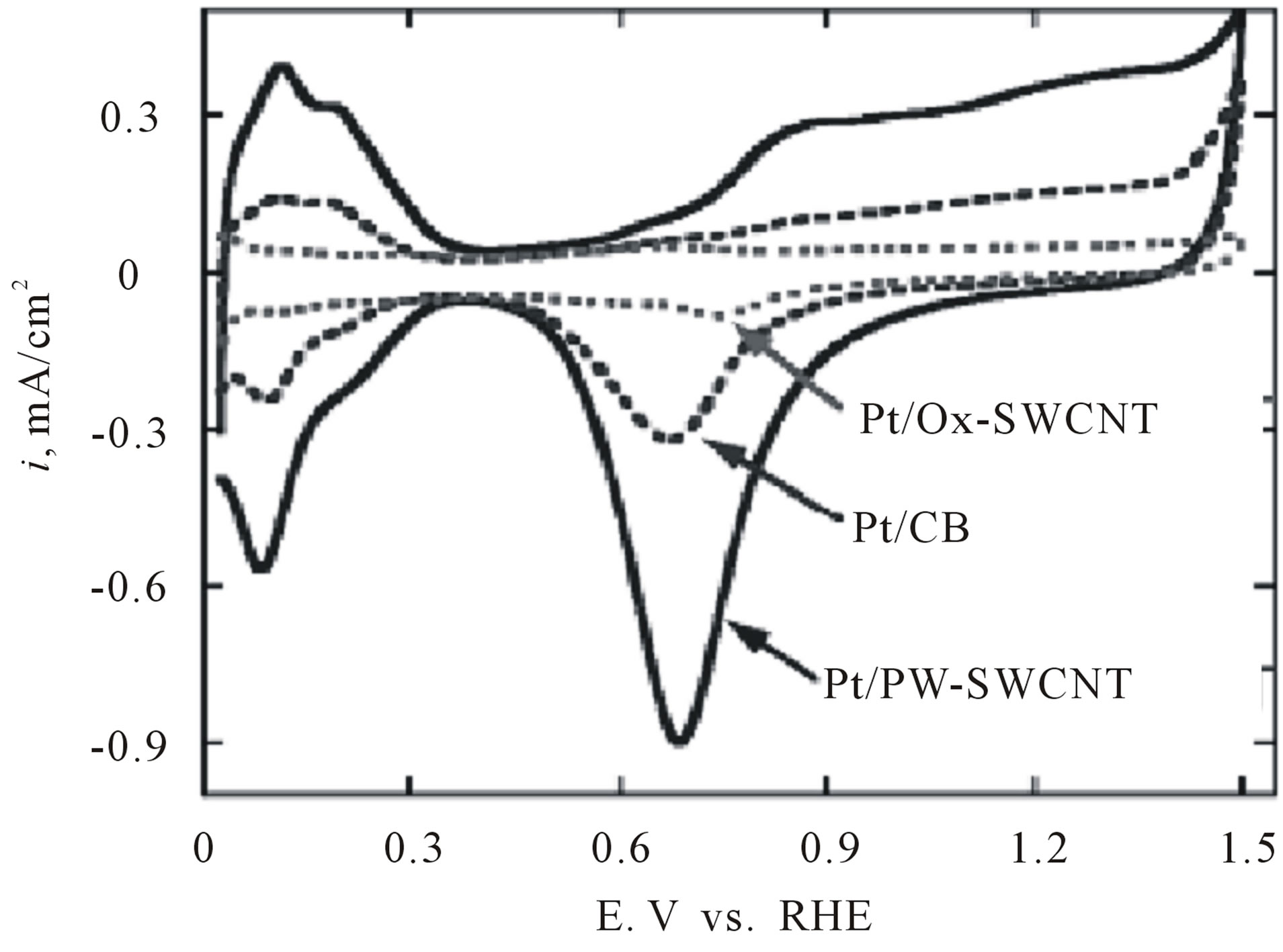
Figure 5. Cyclic voltammograms for Pt/PW-SWCNT, Pt/OxSWCNT, and Pt/CB recorded in 0.1 M HClO4 at a scan rate of 0.02 V/s. The Pt loadings were 14 µg/cm2 [38].
functional groups on the surface of CNTs. Then this electrode was immersed in a solution of the platinum cationcomplex salt for 48 h. As a result of this immersion, the hydrogen ions of the functional group on the surface of the CNT electrode undergo an ion-exchange process with the platinum cation complex. The immersed CNT electrode was then filtrated and washed sufficiently with distilled water. Reduction of the adsorbed platinum complex to its metallic state was carried out by the treatment with hydrogen gas at 190˚C. They observed the Pt nanoparticles to be highly dispersed on the CNTs and their dispersion was much superior to the catalyst prepared by the borohydride method [40].
Shao et al. [26] prepared Multi-walled carbon nanotubes based Pt electrodes (Pt/MWNTs) for oxygen reduction reaction in PEMFCsby depositing Pt nanoparticles on electrochemically functionalized MWNTs with in situ ion exchange method. Figure 6 shows representative SEM images of the MWNT electrodes before (A) and after (B) Pt loading by in situ ion exchange. It can be seen from the images Multi-walled carbon nanotubes


Figure 6. SEM images of MWNT-electrodes before (A) and after (B) Pt loading with in situ ion exchange method [26].
have around 20 nm in diameters. Pt nanoparticles are highly dispersed on carbon nanotubes. They reported that the electrochemical surface area of the ion-exchanged electrode and the conventional electrode was 688.3 and 542.6 cm2/mg Pt, respectively. Also the Pt utilization, which is the ratio of the electrochemical surface area and the chemical surface area, was greatly enhanced on the ion-exchanged electrode (98.2%), as compared with 48.4% for the conventional one. Moreover the activity of the ion-exchanged electrode to ORR was higher than the conventional one.
In other study that was carried out by the Wang and et al. [41] highly dispersed platinum supported on single-walled carbon nanotubes (SWNTs) as electocatalyst was prepared by ion exchange method. The homemade Pt/SWNTs underwent a repetition of ion exchange and reduction process in order to achieve an increase of the metal loading. For comparison, the similar loading of Pt catalyst supported on carbon nanotubes was prepared by borohydride reduction method. The particle morphology, size, and dispersion of Pt nanoparticles deposited on the carbon nanotubes were characterized by transmission electron microscopy it is reported that the particle sizes of Pt catalysts prepared by ion exchange method was remarkably uniform and the dispersions of Pt nanoparticles on the SWNT was good. The average sizes of the particles of all resulted catalysts calculated from the XRD data are consistent with the results by TEM micrographs. As can be seen from XRD (Figure 7) observations, the small platinum particles with a well-defined particle size distribution were deposited on the carbon support by ion exchange method. The formation of small size of Pt nanoparticles attributed to the “anchor effect” of the ion exchange reaction. Compared with the Pt/ SWNTs catalyst prepared by borohydride method, higher Pt utilization was attained on the SWNTs by ion exchange method. Furthermore, in comparison to the ETEK 20 wt% Pt/C catalyst with the support of carbon black, the results from electrochemical measurement (Figure 8) indicated that the Pt/SWNTs prepared by ion exchange method displayed a higher catalytic activity for methanol oxidation and higher Pt utilization, while no substantial increasing in the catalytic activity of the Pt/SWNTs catalyst obtained by borohydride method.
2.1.5. Microwave Heated Polyol Method
Microwave irradiation through dielectric heating loss is fast, simple, uniform, energy efficient and has been widely used in materials synthesis [42]. The polyol process, in which an ethylene glycol solution of the metal precursor salt is slowly heated to produce colloidal metal, has recently been extended to produce metal nanoparticles supported on various substrates. Recently there have been more reported achievements in preparing high purity
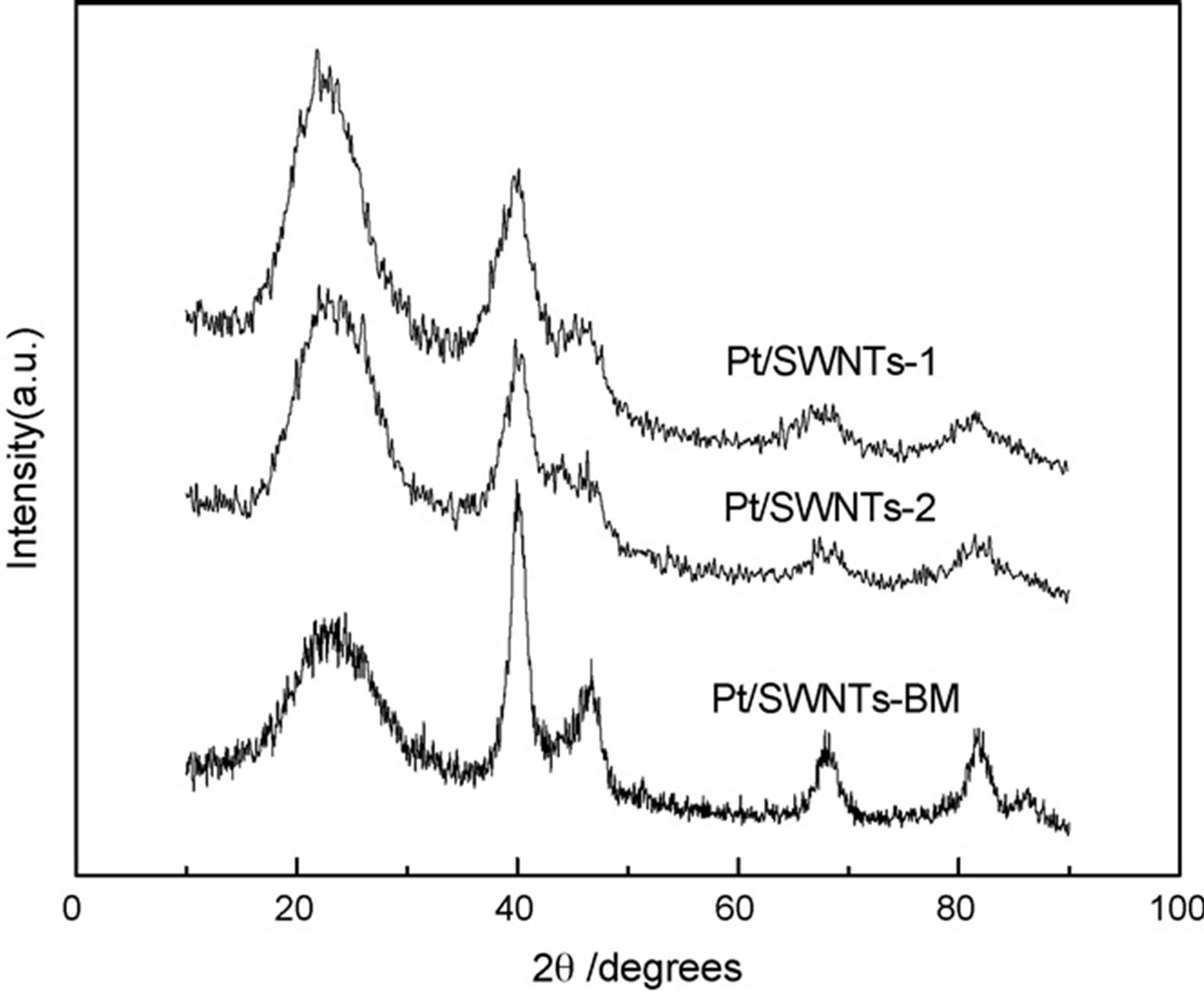
Figure 7. XRD patterns of the Pt/SWNTs catalysts prepared by different methods [41].
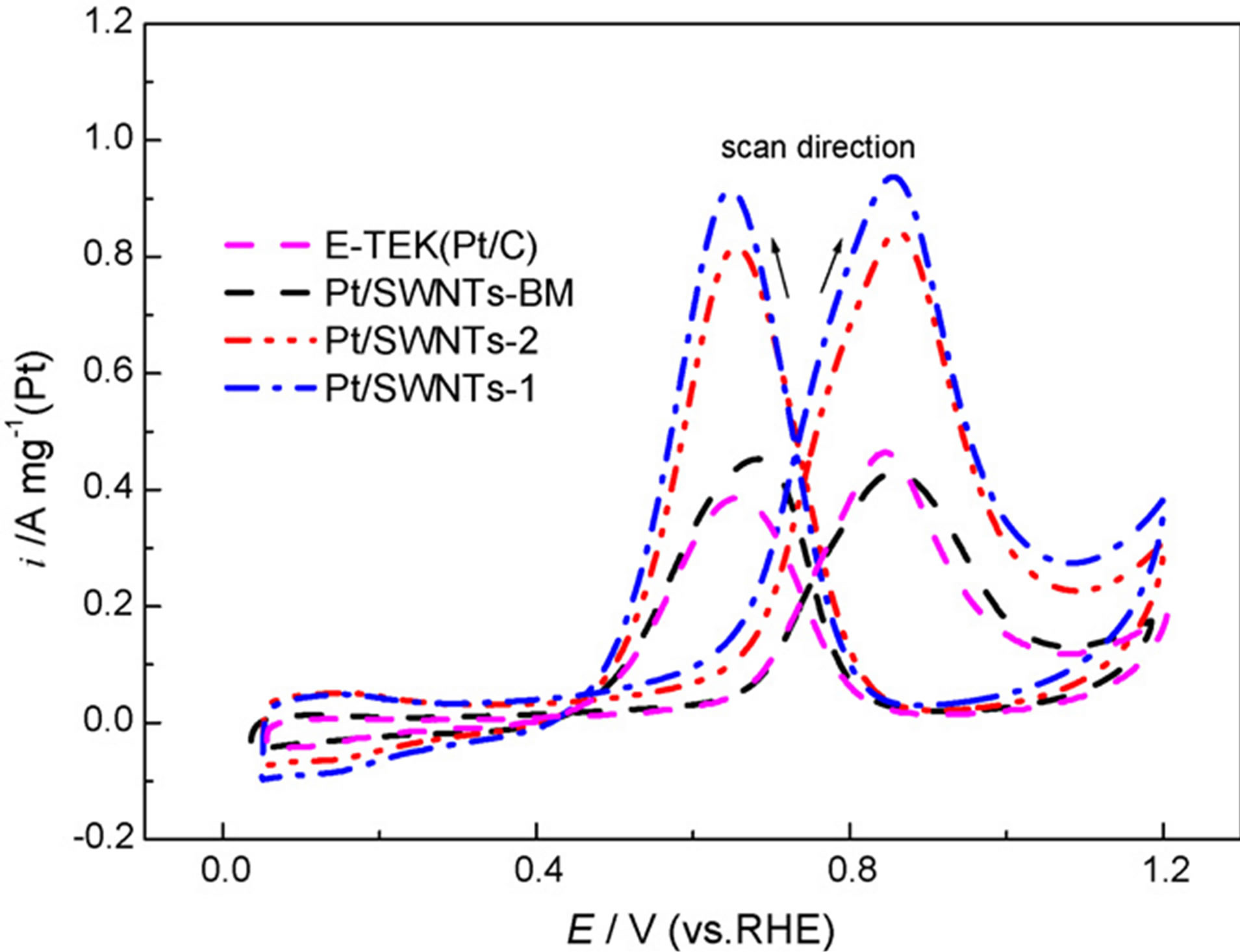
Figure 8. Cyclic voltammograms of methanol oxidation on Pt/SWNTs and Pt/C catalysts. Measurements were performed in 0.5 mol/ L H2SO4 + 0.5 mol/ L CH3OH aqueous solution saturated by Ar. Scan rate: 50 mV/s [41].
Pt or Pt-based nanoparticles supported on CNTs by a microwave-assisted polyol process in literature [43-47]. The polyol process is normally used in preparing colloidal metal particles [48]. In this process, a polyol (most commonly ethylene glycol) solution containing the metal precursor salts is refluxed at 393 - 443 K, where the polyol decomposes homogeneously to release the reducing agent for metal ion reduction [49]. A support material may be optionally present to capture the depositing metal particles [50]. For example, Lordi et al. [51] used the polyol process to prepare Pt supported on single-walled carbon nanotubes for selective hydrogenation. Li et al. [52] used an analogous technique to prepare Pt/CNTs catalyst for fuel cell applications. Conventional heating, with its intrinsic heterogeneous temperature distribution, was used to thermally activate the polyol in these instances. On the other hand, as a rapid, uniform and effective heating method, microwave heating has been used as an attractive alternative for nanosize materials synthesis. Microwave radiations can increase the reaction kinetics by one to two orders of magnitude and promote the formation of uniform metal nanoparticles.
The pH value of the Pt precursor solution is an important factor in controlling the Pt particle size and distribution by the polyol process. The effect of the pH on the Pt particles’ size and distribution were investigated by Li et al. [47]. In their experiments, the pH of the solution was adjusted to the desired value (3.4 - 9.2) by the addition of a KOH solution. Figure 9 shows TEM images of Pt/ CNTs prepared by the microwave polyol process using different values of pH. At a lower pH range (pH 3.6 - 5.8), the Pt nanoparticles are agglomerated and not as well dispersed on the CNT surfaces. In contrast in the pH range of 7.4 - 9.2 less agglomeration has been formed and the Pt nanoparticles dispersed more uniformly on the CNT surface. The direct evidence of the pH effect on the size of Pt was given by TEM images of Pt/CNTs prepared by microwavepolyol heating. As it is shown pH value in the solution plays an important role in controlling the Pt particle size and distribution.
2.1.6. Sputtering Techniques
Sputtering techniques as efficient deposition method can produce anextremely uniform particle distribution and the fabricating process is quite simple. The particle size is determined by controlling the sputtering time and current. Recently, sputtering deposition techniques were used for producing thin platinum films on the surface of CNTs. According to Chen et al. [53], the sputtering deposition method could generate highly uniformed Pt nanoparticles on CNTs compared to those produced by the impregnation deposition method. In their research, the CNTs were synthesized directly on the carbon cloth by a bias-assisted microwave plasma enhanced CVD method and the Pt nanoparticles were subsequently deposited on the CNTs. Wang et al. [54] deposited Pt-Ru electrocatalysts on the directly grown on a carbon cloth(DGCNTs) using sputtering process (Pt-Ru/DGCNT), which were acted as an anode in the DMFC. The diameters of Pt-Ru nanoparticles deposited on the DGCNTs was ca. 3.54 nm, which was the high-degree alloy by X-ray diffraction analysis. The HRSEM and TEM images of Pt-Ru/DGCNT are shown in Figures 10(a) and (b), respectively. From Figure 10(a), the Pt-Ru electrocatalysts are successively deposited on the DGCNTs. It is clear that the electrocatalysts are highly dispersed on the DGCNT, as shown in Figure 10(b). The diameter of electrocatalyst is around 3.5 nm. The electrochemical property was measured by cyclic voltammogram. Comparing of the Pt-Ru/ DGCNT and the conventional Pt/C, Pt-Ru/DGCNT shows a high-

Figure 9. TEM images of microwave-synthesized Pt/CNTs from the ethylene glycol solutions of H2PtCl6 with different pH in the presence of CNTs: (a) pH = 3.6; (b) pH = 5.8; (c) pH = 7.4 and (d) pH = 9.2 [47].

Figure 10. (a) The HRSEM image of Pt-Ru/DGCNT; (b) the TEM image of Pt-Ru/DGCNT and the corresponding SAD pattern showing in the inset [54].
er methanol-oxidation activity.
The advance variation of the sputtering deposition methods found in the literature is to deposit Pt nanoparticles on nitrogen-containing CNTs (N-CNTs) for microDMFC applications [55]. A lot of efforts have been dedicated to the NCNTs [56,57]. It has been reported that the N-CNTs have many advantages over general CNTs including the enhancement of interaction between the nanotube surface and the deposited Pt nanoparticles [58].
While the sputtering technique works well for the direct deposition method, the main drawback is the durability. In most cases the deposition has not strongly adherence to the substrate and under the variable conditions of load and temperature there is a greater probability that the deposits will sinter or dissolute. As discussed, the sputtering technique is a very useful method to achieve an ultra-low Pt loading in the catalyst layer. A unique advantage of the sputtering technique is that the catalyst utilization is extremely high. In addition, the sputtering method accelerates the preparation of a nano-scale Pt catalyst layer with a defined thickness, which could streamline fuel cell water/thermal management and eliminate mass transfer loss. Furthermore, the sputtering process allows the deposition of Pt on various substrates, such as the GDL, membrane, and other supports. However, although the sputtering CLs showed remarkably higher mass activity than the conventional layer, the validated output power density is still low. For example, Tang et al. [59] sputter deposited nanosized Pt nanodots (2 - 3 nm) as catalyst on CNT prepared in-situ on carbon paper. The system acting as a combined gas diffusion layer (GDL) and catalyst layer displayed a high maximum power density of 595 mW/ cm2 using a catalyst loading of 0.04 mg/cm2 Pt on the cathode side. This was significantly higher than the Pt/Vulcan XC 72R-based electrode (435 mW/cm2) with equal Pt loadings and that of the reference electrode with sputtered Pt on CNT/CB blend layer (530 mW/cm).
2.1.7. Supercritical Fluids
The use of supercritical fluids (SCF) as “green” solvents for the synthesis and processing of nanomaterials has gained considerable interest in recent years. Supercritical carbon dioxide (scCO2) is particularly attractive for electrocatalysts processing as it is accessible under moderate conditions (Tc =31˚C and Pc = 7.38 MPa), abundant, low-priced, non-flammable, non-toxic, and environmentally benign [60-62]. This process involves the dissolution of a metallic precursor in a supercritical fluid and the introduction of a porous support to the solution. After adsorption of the precursor on the support, the metallic precursor is converted to its metal form by chemical or thermal reduction. Using a SCF as the processing medium for synthesis of electrocatalysts has many advantages which are directly related to the special properties of the SCFs. Supercritical carbon dioxide (scCO2) allows reactive components to penetrate inside the porous materials themselves, partitioning into the inner regions of the porous supports. This promising catalyst preparation technique results in small particle sizes and homogeneous dispersions. An additional advantage of this technique is the ability to thermodynamically control the metal loading [63].
Lin et al. [64] used a supercritical fluids (SCFs) method as a rapid, direct, and clean approach to prepare Pt/CNT catalyst for DMFCs. Bimetallic platinum-based electrocatalyst nanoparticles supported on carbon nanotubes for direct methanol fuel cells have also been produced using scCO2 [65,66]. Bayrakceken et al. [67] used the scCO2 deposition method to disperse Pt-based electrocatalysts on various carbon supports such as MWCNTs, Vulcan XC 72R (VXR) and black pearl 2000 (BP2000). Commercially available Pt/C-ETEK was used for comparing the synthesized catalysts. XRD and HRTEM results demonstrated that the scCO2 deposition technique enables a high surface area metal phase to be deposited, with the size of the Pt particles ranging from 1 to 2 nm. HRTEM images obtained from the synthesized and commercial catalysts are presented in Figure 11 for Pt/ MWCNT (a), (b); Pt/VXR (c), (d); Pt/BP2000 (e), (f) and ETEK Pt/C (g)-(j).
The electrochemical surface areas (ESAs) of the prepared electrocatalysts were compared to the surface areas of commercial ETEK Pt/C (10 wt% Pt) and Tanaka Pt/C (46.5 wt% Pt) catalysts (Figure 12). The CV data indicated that the ESAs of the prepared Pt/VXR and Pt/ MWCNT catalysts was about three times larger than that of the commercial ETEK catalyst for same (10 wt% Pt) loadings. Oxygen reduction activity was investigated by hydrodynamic voltammetry. From the slope of KouteckyLevich plots, the average number of electrons transferred in the oxygen reduction reaction (ORR) was 3.5, 3.6 and 3.7 for Pt/BP2000, Pt/VXR and Pt/MWCNT, correspondingly, which indicated almost complete reduction of oxygen to water.
2.2. Fabrication and Performance of Carbon Nanotubes Based Membrane Electrode Assembly
The conventional process for constructing CNT-based catalyst layers in PEMFC is to disperse CNTs in a binder (such as Nafion) to form a slurry, and then coat on a carbon cloth (gas diffusion layer) [68]. A common problem in this process is that the addition of the binder has a tendency to isolate carbon nanotubes in the electrocatalyst layer, resulting in poor electron transport and reduces the Pt active surface. To overcome this problem, many efforts have recently been made. For instance, researchers tried to grow or filter carbon nanotubes directly onto a carbon cloth and then subsequently depositing Pt selectively on the carbon nanotubes [69-72]. In these efforts, the contact resistance between the two layers is minimized and the utilization rate of the noble metal catalyst can be increased by abolishing the separation of the carbon particles from the electrode support. A thin film of CNTs loaded with nanosized Pt prepared by filtration method was applied as a cathode catalyst layer by Haddon et al. [73], which showed high performance at ultra low Pt loading due to the efficient proton transport in a small thickness.
Li and co-workers [72] reported a simple preparation procedure (filtration method) for the fabricating MEA using CNTs films as a support for PEM fuel cells. They deposited the Pt nanoparticles on the CNTs before the film formation and then used filtration as a means to form an oriented film of Pt/CNTs on the Nafion membrane. Pt particles were dispersed on the CNT’s surface through a chemical reduction of H2PtCl6 by ethylene glycol. The Pt/CNT architecture was then filtered through 0.2-µmpore hydrophilic nylon filter paper. The dispersed film was then transferred onto a Nafion membrane by pressing the CNT-coated side of the filter onto the Nafion membrane. Finally, the oriented Pt/CNT-film-coated Nafion membrane, and a gas diffusion layer were hot pressed to obtain an MEA. A higher performance was gained with oriented Pt/CNT-based MEA than Pt/C and non-oriented Pt/CNT-based MEAs.
Recently, a new style for composite electrode fabrication involving the growth of CNTs directly on the carbon
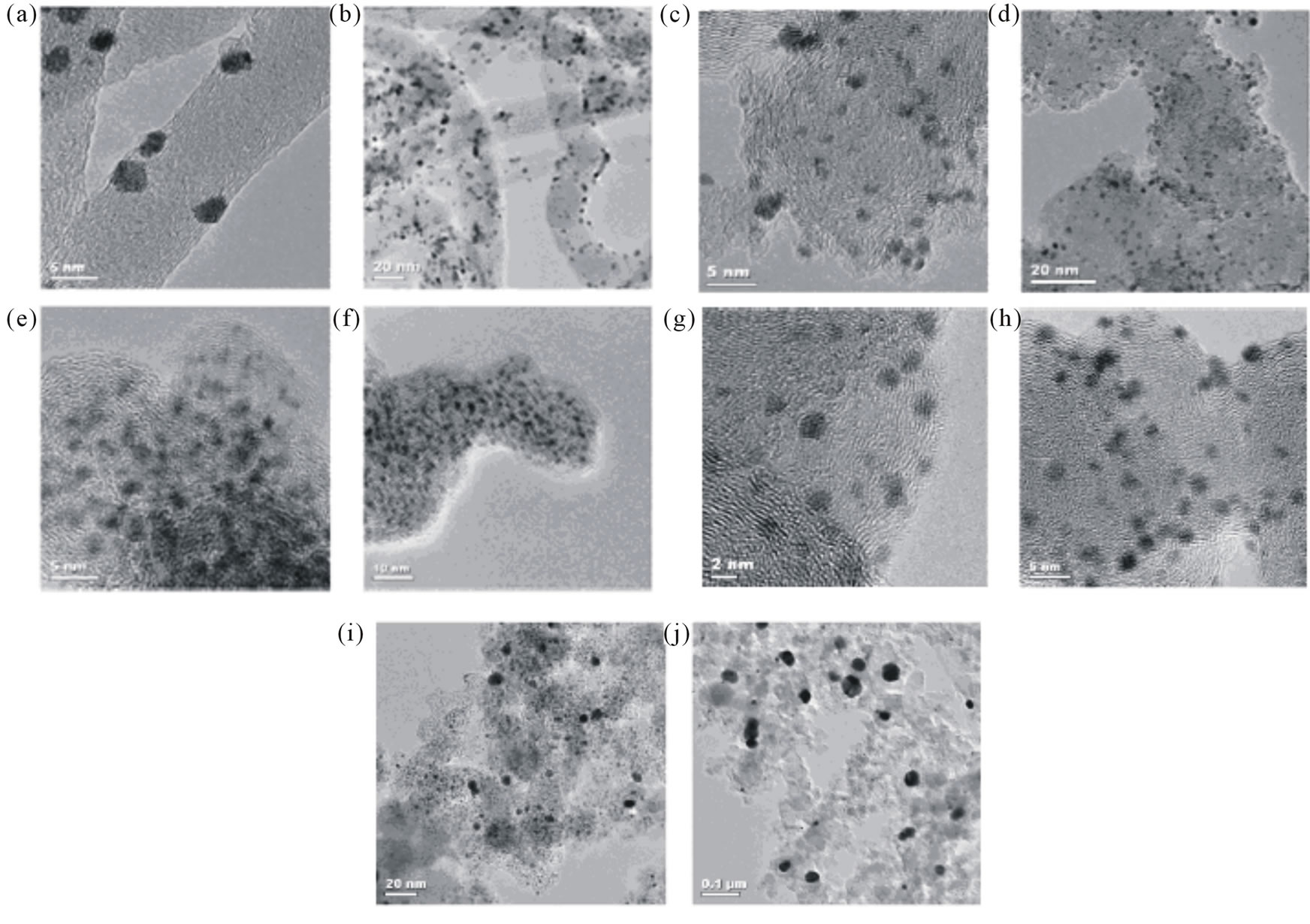
Figure 11. HRTEM images for (a), (b) Pt/MWCNT; (c), (d) Pt/VXR; (e), (f) Pt/BP2000; (g)-(j) Pt/C (ETEK) [67].
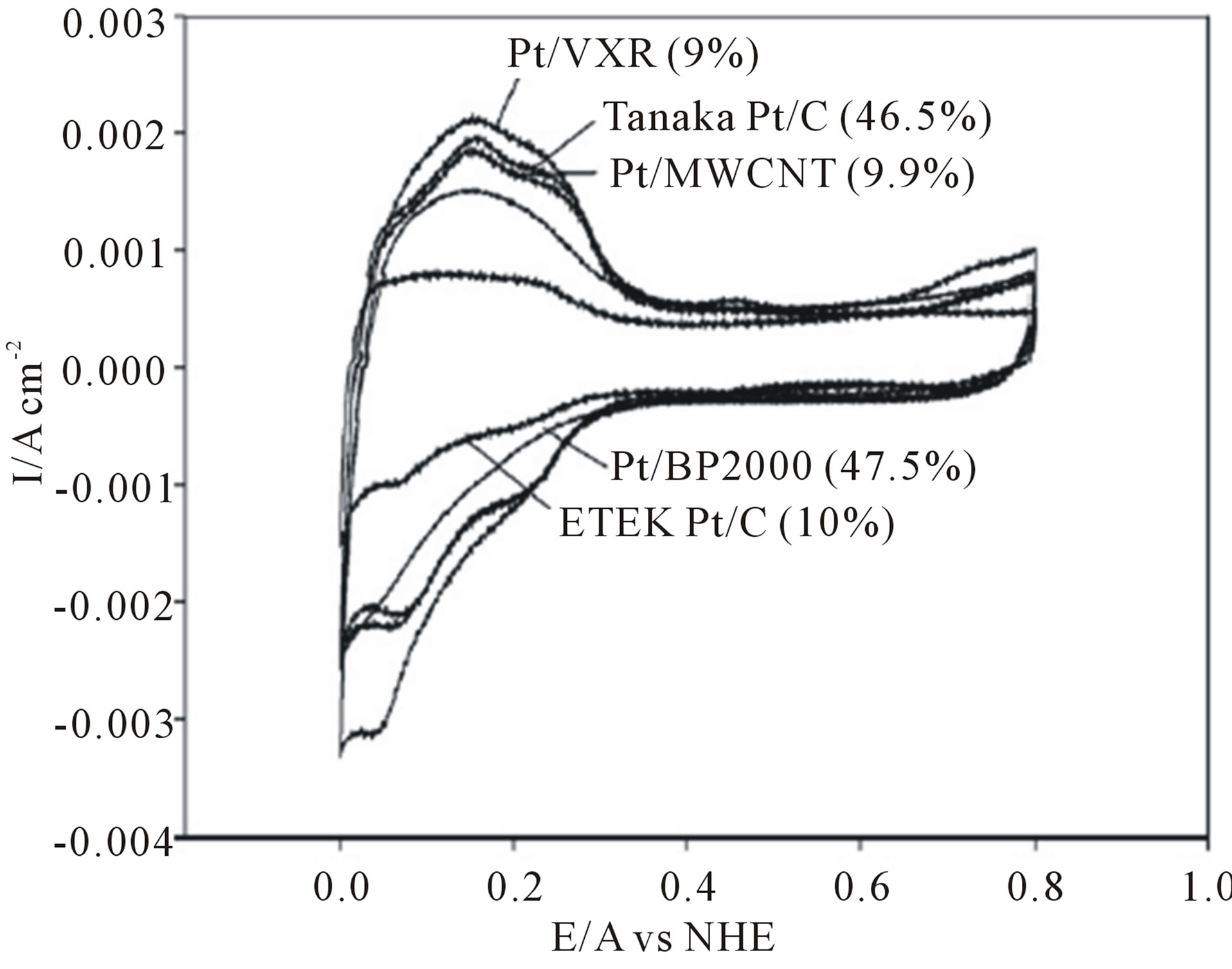
Figure 12. Cyclic voltammogram for the synthesized catalysts in 0.1 M HClO4 in H2 atmosphere at a scan rate of 50 Mv/s [67].
fibers of a fuel cell baking with subsequent deposition of Pt nanoparticles was established [69,74,75] Randomly oriented single or multiwalled carbon nanotubes can be easily converted into highly conducting thin porous networks appropriate for gas diffusion electrodes in fuel cells. High dispersion and electrocatalytic properties of Pt nanoparticles on SWNT bundles [76,77] Partially aligned MWNTs grown on commercial carbon fibres [78] combine the well known properties of conventional carbon electrodes with the high specific surface area of MWNTs (up to 1000 m2/g [79]). Totally aligned nanocarbon materials can be prepared by the vertical growth of MWNTs on thermally insulating substrates allowing well-defined three-dimensional distribution of properties. Aligned MWNTs are discussed as gas diffusion layers [80] and catalyst support by several authors [81,82].
2.3. Test in a Single Fuel Cell
From the practical point of view, the single cell test is the ultimate evaluation criterion for new electrocatalysts materials. A lot of experiments have been performed on the single cell in real fuel cell condition in order to evaluation the fuel cell performance of Pt nanoparticles supported on CNTs at the cathode of H2/O2 fuel cells or direct methanol fuel cells by many authors [14,18,52,69,72,75,83-88]. Without exceptional it has been shown that the performance of a CNT-based MEA is better than that of conventional Pt/C MEA. For example, Matsumoto and coworkers [18] conducted the fuel cell tests of the MEA with CNTs used as a support for Pt catalysts with different two Pt precursors; H2PtCl6·6(H2O) or K2PtCl4 at the cathode. The performance of the fuel cell for the KPt-CNT, HPt-CNT, and Pt-CB electrodes are shown in Figure 13. The performance of the Pt supported CNT electrodes is comparable to the Pt-CB electrodes in Figure 13(a), and

Figure 13. Current potential curves for the Pt-CB, the HPt-CNT, and the KPt-CNT electrodes. The curves below 500 mA/cm2 were enlarged in (b) [18].
the KPt-CNT electrodes showed the highest voltages below 500 mA/cm2 in Figure 13(b). They suggest that the higher voltages of the KPt-CNT related to the formation of more effective triple-phase boundaries on the KPt-CNT electrodes than the other two electrodes.
In another study Matsumoto et al. [88] found that a 12 wt% Pt deposited CNT electrode provides 10% higher voltage than 29 wt% Pt deposited on Vulcan and reduces Pt usage by 60% in PEMFCs when using hydrogen and oxygen. With respect to comparing the performance of Pt-Ru/CNTs (MI) with Pt-Ru/C (E-TEK) catalyst that were conducted by Cui and coworkers [27] the single cells with Pt-Ru/CNTs (MI) catalyst exhibited a power density of 61 mW/cm2, about 27% higher than those single cells with commercial Pt-Ru/C (E-TEK) catalyst (Figure 14).
Saha and co-workers [89] developed a synthetic method to deposit Pt nanoparticles on CNTs that were grown on commercially-used carbon paper by the reduction of the Pt precursor with glacial acetic acid. Figure 15 shows the single cell performance for the MEA made with a CNTbased electrode as the cathode and standard E-TEK electrode as the anode for H2/O2 fuel cells. Compared with the standard Pt/C electrode, the CNT-based electrode exhibited higher single-cell performance in a H2/O2fuel cell. According to Figure 16 at a constant cell voltage of 0.6 V, the current density of the Pt/CNT/carbon paper composite is 1.58 A/cm2 which is 27% higher than the standard E-TEK electrode (1.16 A/cm2). The corresponding power densities normalized on the basis of Pt loading were 2.19 W/mgPt (Pt/CNT/carbon paper composite) and 1.42 W/mgPt (standard E-TEK electrode) at 0.6 V, showing a significant increase in the power density of about 0.77 W/mgPt for the Pt/CNT/carbon paper composite. It is clearly obvious that the current density at 900 mV for the Pt/CNT/carbon paper composite is meaningfully higher than the E-TEK electrode (approximately 66%), which attributed to the better dispersion of Pt nanoparticles on the CNT’s surface and to the 3D structure of CNT-based electrodes.
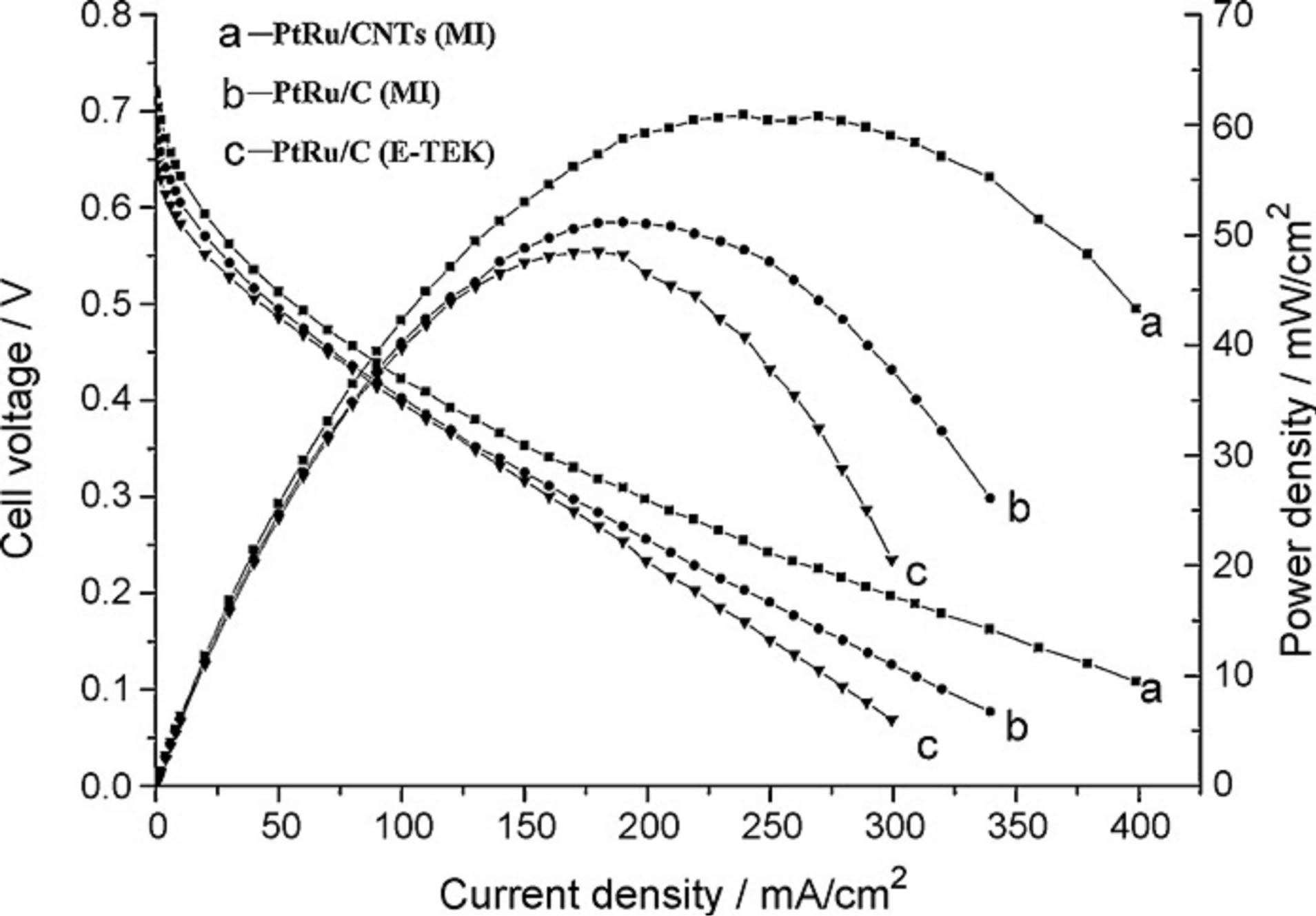
Figure 14. Single cell performance using different PtRu catalysts at the anode at 80˚C [27].
Carmo and co-workers [90] conducted polarization curve measurement with noble metal catalysts supported on carbon nanotubes (MWNT and SWNT) and also on a high surface area carbon powder Vulcan XC-72, for proton exchange membrane fuel cells fed with hydrogen contaminated with CO and also for the direct methanol fuel cell. A high performance was obtained with PtRu supported on nanotubes for H2 + 100 ppm CO, although it was analogous to that presented by PtRu on Vulcan XC-72 with an overpotential of 100 mV at 1 A/cm. Results for the DMFC showed power densities more than 100 mW/cm2 at 90˚C and 0.3 MPa and the activity of the anodes followed the sequence: PtRu/MWNT > PtRu/ Vulcan XC-72 > PtRu/SWNT.
3. Methods for Depositing Pt Catalysts on Carbon Nanofibers (Pt/CNFs) and Performance of the CNFs Supported Electrode in PEM Fuel Cell
In recent years, Carbon nanofibers (CNFs) have attracted interest as electrocatalyst support for PEM fuel cells due to their excellent mechanical, electrical and thermal properties. Within several supports, carbon nanofibers blend
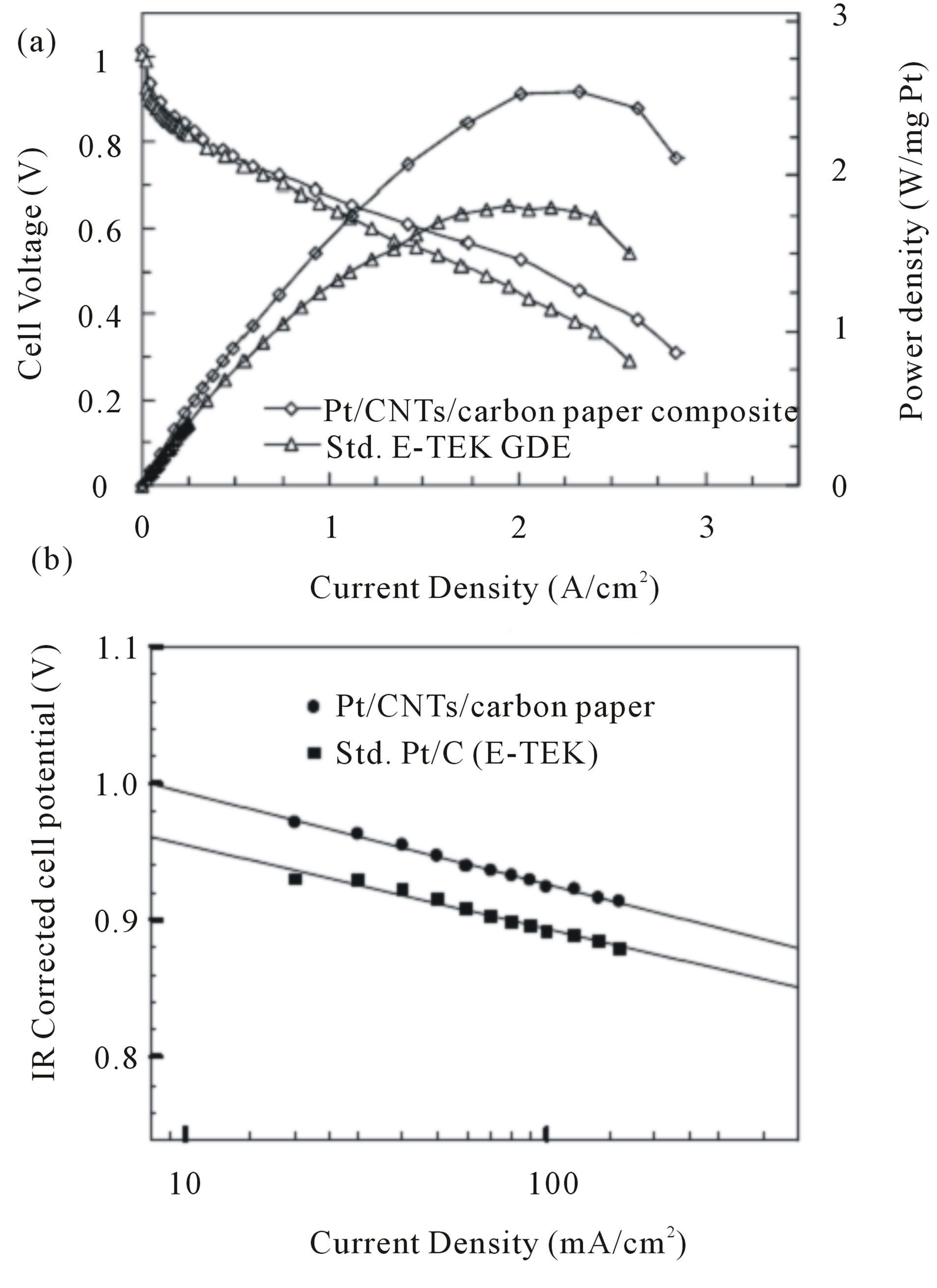
Figure 15. (a) Polarization characteristics of the MEAs fabricated with of CNTs electrode (0. 42 mgPt/cm2) and standard E-TEK electrode (LT140E-W; 0.5 mgPt/cm2) as cathode electrodes for H2/O2 at 80˚C, Nafion 112 membrane, 25/30 psig anode and cathode back pressure. Anode electrodes were E-TEK electrode with 0.5 mgPt/cm2; (b) IR corrected Tafel plots for comparison of kinetic parameters [89].
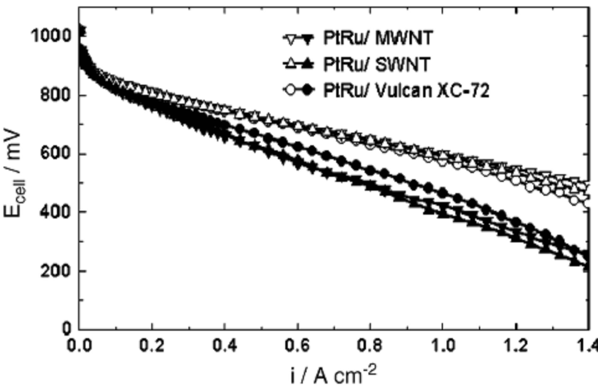
Figure 16. Potential vs. current density for PtRu/C anodes with 0.4 mg noble metal/ cm2 on different supports [90].
two properties that rarely coexist in a material: a high mesoporosity and a high electrical conductivity, due to their particular crystalline structure. Moreover, the ratio of edge atoms to basal atoms of CNFs is controllable, which provides a means to adjust the deposition of and the interaction with the metal [91-93]. Bessel et al. [94] utilized Pt/CNFs and Pt/(Vulcan XC-72) as the catalysts for methanol oxidation, and found that the platelet CNF (p-CNF) and tubular CNF (t-CNF) supports were superior to fish-bone CNF (f-CNF) or Vulcan XC-72 in terms of the activities. They also showed that 5 wt% Pt supported on p-CNT or t-CNT would be as active as 25 wt% Pt supported on f-CNF or XC-72. However, Ismagilov et al. [94] reported that the performance of the catalysts supported on p-CNF f-CNF was lower than those supported on Vulcan XC-72 and amorphous supermicroporous carbons (ASC). Tsuji and coworkers [95] deposited PtRu alloy nanoparticles supported on three types of carbon nanofibers (CNFs); platelet, herringbone, and tubular ones by using a microwave assisted-polyol method. The dependence of particles sizes and electrochemical properties on the structures of CNFs was examined. The methanol fuel cell activities of PtRu/CNFs measured at 60˚C were 1.7 - 3.0 times higher than that of a standard PtRu (29 wt%, Ru/Pt atomic ratio, 0.92) catalyst loaded on carbon black (Vulcan XC72R) support. Based on results the greatest electrocatalytic activity was obtained for the platelet CNF, which is characterized by its edge surface and high graphitization degree.
Since the publication of the works of Bessel et al. [93] and Steigerwalt et al. [96,97] several studies have shown the advantageous use of CNFs for the electrooxidation of methanol, the anodic reaction of direct methanol fuel cells (DMFCs) [98-100]. However, few works have dealt with the performance of CNF supported platinum for the oxygen reduction reaction (ORR) in a direct methanol fuel cell system. Ismagilov et al. [94] found an inferior ORR performance of platelet and parallel CNFs as support for Pt by comparison with the most used commercial carbon black, Vulcan XC-72R. Instead, Yang et al. [101] found a superior performance for the oxygen reduction when supporting Pd on CNFs. The irregularity within these results could be ascribed to the differences among the properties of different CNFs as well as the different deposition methods employed. Most of the deposition methods that were described for CNTs supported electrocatalyst previously are used for deposition of Pt and Pt-based metals on CNFs.
Sebastian and coworkers [102] prepared Pt catalyst supported on CNFs by different deposition methods and the obtained catalysts have been studied by different chemical techniques. In the first method, named sodium borohydride method (SBM), an aqueous solution of sodium borohydride (NaBH4) was used as reduction agent. Firstly the precursor solution (an aqueous solution of H2PtCl6 3.2 mmol/ L) slowly added to a dispersion of carbon in ultrapure water under sonication and then the pH of the dispersion is adjusted to 5.0. After that, the sodium borohydride aqueous solution (26.5 mmol /L) is dropwise added, keeping temperature under 18˚C and in the presence of sonication. Subsequently, the catalyst is filtered and thoroughly washed with ultrapure water, and then dried overnight at 60˚C. The second method, named formic acid method (FAM), consisted on the use of an aqueous solution of formic acid as reduction agent. Firstly, the carbon is dispersed in a 2 M formic acid aqueous solution, prepared from high purity reagents, and then heated up to 80˚C. Then an aqueous solution of H2PtCl6 4.2 mmol/L was slowly added to the dispersion under continuous stirring at 80˚C ± 1˚C. Consequently like the first method, the catalyst was filtered and carefully washed with ultrapure water, and then dried overnight at 60˚C. Platinum has then been supported on functionalized carbon nanofibers by two different procedures, obtaining Pt crystal sizes between 5.4 nm and 8.1 nm and a complete reduction of the metallic phase. Two of the catalysts obtained by SB method presented higher current densities than those obtained for commercial catalysts, ranging from 32 (CNF LT-F) to 53 mA/cm2 (CNF HT-F), whereas the Pt/Vulcan-ETEK presented 28 mA/cm2. Samples obtained by FA method show, on the other hand, stationary current densities, achieving similar values that commercial catalyst when supporting Pt on the most conductive carbon nanofibers: CNF HT-F.SB method gave the impression to be better than FA method with respect to electrochemical activity, CO tolerance and performance whereas FA method offerings better stability.
The geometric effect of graphite nanofibers (GNFs) as a support for PtRu electrocatalysts on the oxidation of methanol for direct methanol fuel cells was studied using X-ray diffraction, field emission transmission electron microscopy (FETEM) and electrochemical measurements [103]. A high loading of 60 wt% PtRu catalystwas dispersed on GNFs. Further, the shape of the supported metal particles was affected by interactions with the GNFs. Electrochemical analysis indicated that GNFsupported PtRu catalysts resulted in an increased catalytic activity of about 100% over that of Vulcan XC-72 supported catalysts. FETEM data indicate that the enhanced activities result from a geometric modification of the catalyst particles by specific interactions between the GNFs and the supported PtRu nanoparticles.
Sebastian et al. [104] also studied the influence of carbon nanofiber support properties for the oxygen reduction reaction (ORR) in proton conducting electrolytebased direct methanol fuel cells. The synthesis and deposition of platinum nanoparticles was carried out by the microemulsion method, using a commercial surfactant (Brij_30, Sigma Aldrich), n-heptane as the non-polar phase and 2-propanol as co-surfactant. Briefly, the surfactant and n-heptane were blended and agitated. The platinum precursor (H2PtCl6) dissolved in aqueous solution (0.008 M) was then dropwise added to the mixture. Subsequently, 2-propanol was added until a visually transparent mixture was observed, demonstrating the formation of the microemulsion. After 4 h of stirring, NaBH4 was gently added in 0.1 M aqueous solution to the microemulsion under continuous stirring. The suspension was stirred overnight and then it was slowly added to a suspension of carbon in ethanol under sonication and continuously stirred for 16 h. The quantities were adjusted for a Pt loading of 40 wt%. The catalyst was then carefully washed with ethanol and water and finally dried overnight at 70˚C. Half-cell studies determined that the ORR activity is enhanced when using a CNF with improved graphitization.
Knupp and coworkers [10] investigated the effects of water content, and metal loading on the average Pt particle size and electrochemically active surface area (ECSA) using conventional refluxing and microwave irradiation techniques on the deposition of CNF supported Pt. Optimization of deposition conditions leads to higher ECSA than seen in a commercially available carbon black supported catalyst.
Tang and co-workers [98] employed an electrochemical method for the deposition of Pt nanoparticles on graphitic carbon nanofibers (GCNFs). In their efforts, Pt nanoparticles were electrodeposited on a GCNF/graphite working electrode from an acidic solution of H2PtCl6 by cyclic voltammetry under the condition of a deposition potential of +0.1 - −0.25 V vs. SCE and a sweep rate of 15 mV/s. Before the Pt particle deposition, the GCNFs/ graphite electrode was pretreated in 30 wt% HNO3 aqueous solution for 40 min to remove the metallic nickel catalyst. To further increase the electrochemical activity of the surface of the GCNFs in the water solution, the GCNFs/graphite electrode was then cycled in the range of −0.15 - +1.3 V at a sweep rate of 50 mV/s in 0.5 M H2SO4 for 20 cycles. They observed that the Pt nanoparticles are uniformly dispersed on the whole surface of the GCNFs with a diameter of about 40 - 50 nm, which is about 2 times smaller than that of the Pt/graphite electrode (100 nm).
In another investigation Kim and coworkers [105] employed electrochemical deposition method on Carbon nanofibers (CNFs) web supported platinium nanoparticles at sweep times of 5, 10, 20 and 40. In their experiments the CNF webs were attached onto glassy carbon substrate with the aid of 0.1% Naflon solution. A 10 mM hexachloroplatinic acid (H2PtCl6) was dissolved in 0.5 M HCl aqueous solution. A potential was swept from −0.7 to −0.2 V (versus Ag/AgCl) with a scan rate of 20 mV/s at four mentioned sweep for the deposition of Pt nanocrystalline particles over CNF webs. Particle size and loading level (wt%) of Pt were found to increase from 10.7 to 18.6 nm and 3.3 to 7.0 6%, respectively with the increase of sweep times (Figure 17). The results of elec-
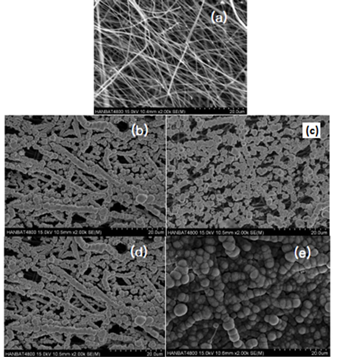
Figure 17. SEM images of (a) uncovered and Pt incorporated CNF prepared by potential sweep method as a function of sweep times of (b) 5, (c) 10 and (d) 20, (e) 40 [105].
trocatalytic activity of the nano Pt/CNF composite which was demonstrated by linear voltammetrty, cyclic voltammetry and impedance spectra showed increment in catalytic activity with the increase of sweep time.
Oh et al. [106] examined the effect of chemical oxidation of carbon nanofibers (CNFs) on the electrochemical carbon corrosion in polymer electrolyte membrane (PEM) fuel cells. In their experiments with increasing time of chemical oxidation treatment using an acidic solution, more oxygen functional groups are formed on the surface of CNF resulting in an increasingly hydrophilic carbon surface. This effect contributed to improvements in Pt loading and the distribution of Pt particles on carbon supports. However, the chemical oxidation treatment is found to accelerate electrochemical carbon corrosion. The oxygen functional group and the hydrophilic nature of CNFs after chemical oxidation treatment are believed to inspire the formation of CO2. From the observed results, the authors concluded that the chemical oxidation of CNFs is beneficial for catalyst loading and distribution. On the other hand, however, it reduces the durability of the PEM fuel cells caused by the electrochemical carbon corrosion.
Steigerwalt et al. [96] reported the preparation and characterization of a Pt-Ru/GCNF nanocomposite where the GCNF support has the “herringbone” atomic structure. Comparative testing of this nanocomposite and unsupported Pt-Ru colloid as anode catalysts in a DMFC revealed 50% higher performance for the Pt-Ru/GCNF nanocomposite. Park et al. [107] reported the novel results regarding the effects of electrospun carbon nanofibers (e-CNF) as a catalyst support by comparison with the commercial Vulcan XC-72R. The e-CNF was synthesized by stabilizing and carbonizing the electrospun PAN-based fibers. The e-CNF showed an average diameter of 250 nm with a rough surface and was partially aligned along the winding direction of the drum winder. The characteristic morphology was fundamentally dependent on the shape of the carbon materials. The average pore size of the e-CNF was 2.36 nm, while that of the XC-72R was 10.92 nm as shown in Figure 18. The morphology of e-CNF was developed by shallow pores with rough surfaces due to the effects of electrospinning and carbonization, while that of the XC-72R was largely developed by mesopores rather than micropores due to the granular shape.
Moreover for performance optimization purpose tubular carbon nanofibers with an average diameter of 150 nm was investigated as a possible material for the electrodes preparation for polymer electrolyte membrane fuel cells [108]. Well-dispersed Platinum particles with an average crystallite size of 4.6 nm are deposited on sur-
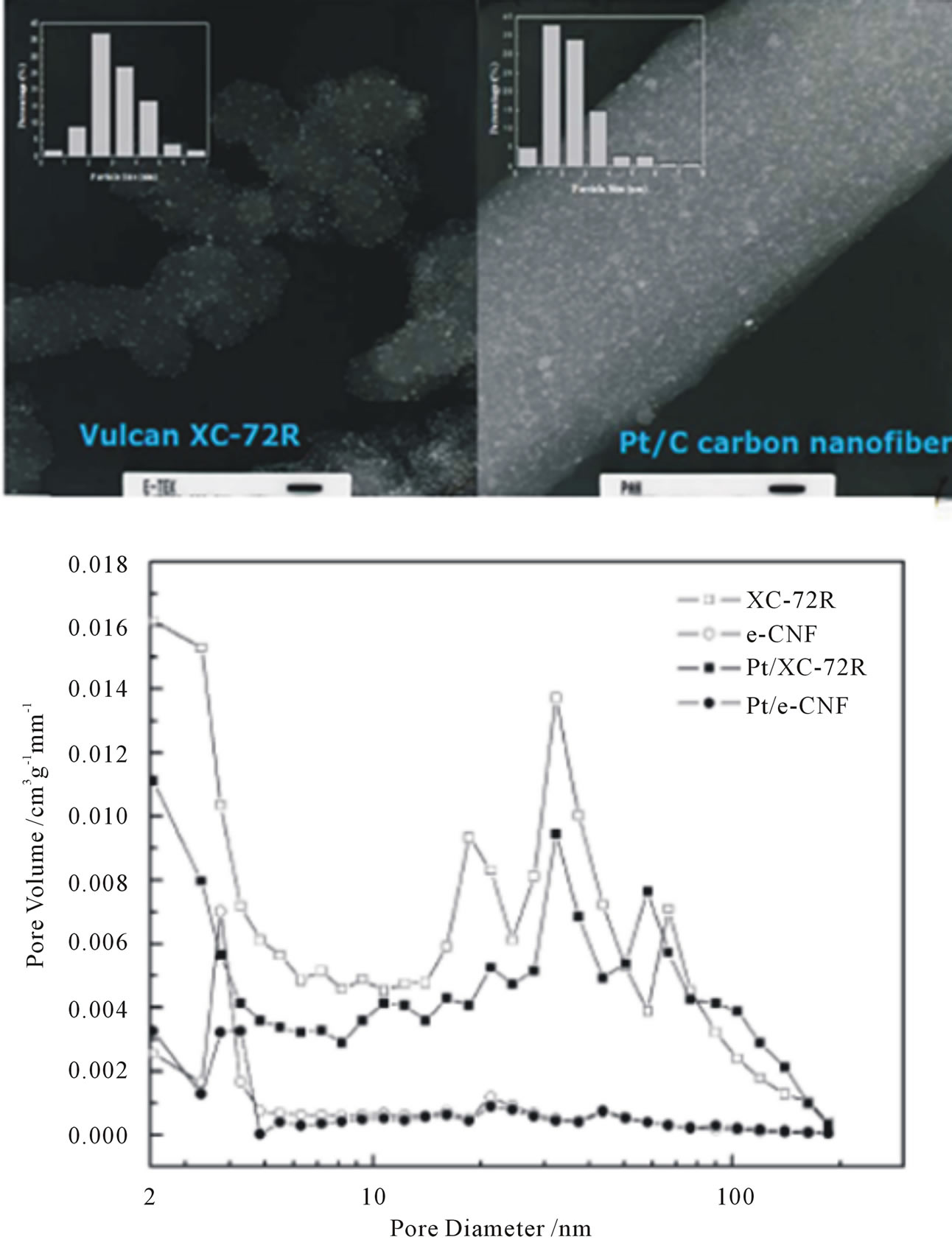
Figure 18. SEM micrographs of fine dispersed Pt coating on carbon (Vulcan XC-72) and Pt dispersed CNFs as well as their pore size distribution pattern [107].
face-oxidised fibers to be used as a catalyst support with an impragnation method. The carbon nanofiber-based electrodes are prepared by a sedimentation method without the use of organic solvents. This method allowed an exact setting of the fiber and binder content and the catalyst loading. The electrodes were optimized by varying the thickness of the gas diffusion layer and its binder content as well as the thickness of the active layer. These optimized electrodes showed a considerably better performance comparing to carbon black based electrodes with the same catalyst loading prepared by a spraying process using the same type and amount of electrolyte in the membrane electrode assembly. By reducing the Platinum content from 0.7 to 0.2 mg/cm2, catalyst utilization is considerably increased.
Figure 19 exemplifies the CVs of an MEA with CNFbased electrodes.
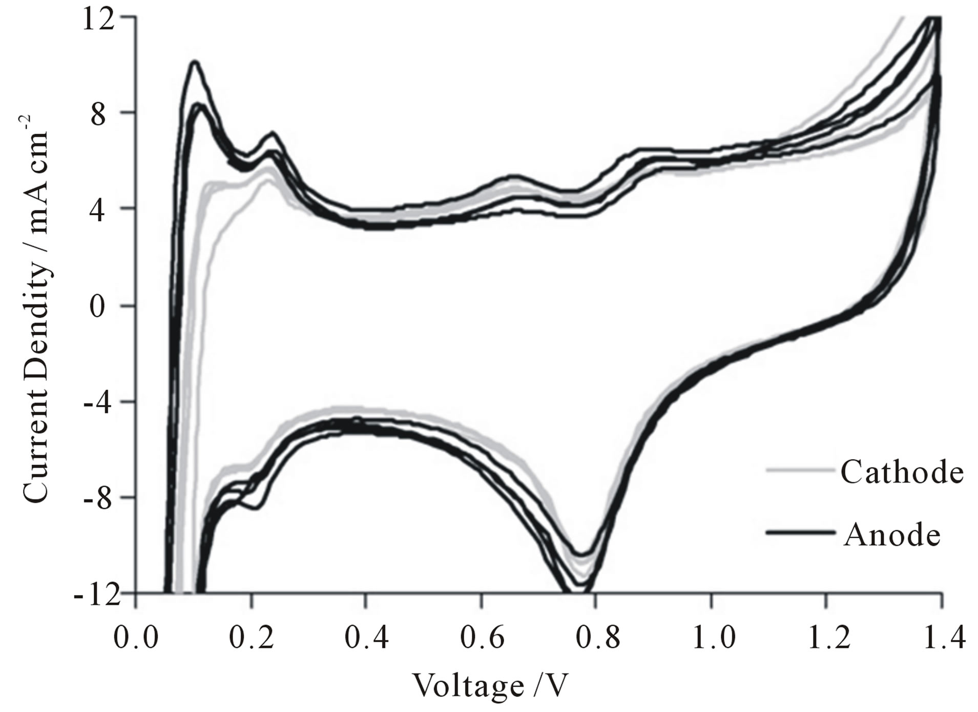
Figure 19. CVs of a CNF based MEA (GDL: 21 wt% PTFE, 6.6 mg/cm2 CNFs; AL: 2.9 mg/cm2 CNFs, 0.7 mg/cm2 platinum [108]).
MEA Fabrication and Performance Evaluation toward the Single Cell Test
Li and coworkers [109] reported a preparation procedure for the MEA using CNFsas a support for proton exchange membrane fuel cell. In their experiments inexpensive stacked-cup carbon nanofibers (SC-CNFs) supported Pt nanoparticles with a loading from 5 to 30 wt% were prepared through a modified ethylene glycol method. For preparation of the catalyst coated membrane (CCM), they modified a self-developed filtration method to make compact Pt/CNFs films onto both sides of Nafion membrane as anode and cathode catalyst layers. Pt/SC-CNFs suspension in ethanol with known catalyst quantity was drawn through a 0.2-lm-pore polycarbonated filter paper. After filtration, a 5 wt% Nafionsolution was used to spray on the surface of the filtrated Pt/ SCCNFs solid, the Nafion weight ratio was altered from 30 wt% to 50 wt% for cathode and was constant 50 wt% for anode. The filtrated Pt/SC-CNFs catalysts were transferred onto Nafion 112 membrane by hot-pressing two catalyst coated sides of the filters onto the Nafion membrane to produce a CCM. The cathode Pt loading was 0.10 mg/cm2 and 0.20 mg/cm2, while the anode catalysts loading was from 0.025 mgPt/cm2, 0.05 mgPt/cm2 to 0.20 mgPt/cm2, respectively. Nylon filter was also used to make a MEA to study the influence of filter’s surface properties on the “catalyst transfer efficiency”. Pt/C catalyst (20 wt%, BASF-Fuel Cell) with different Nafion ratio ranging from 15 wt%, 30 wt% to 50 wt% were sprayed directly on GDL to prepare conventional anode and cathode samples. The SC-CNFs based MEAs with an active electrode area of 4.4 cm2 (2.1 cm) were obtained by hot-pressing a cathode diffusion layer, a CCM and an anode diffusion layer with a pressure of 50 kg/cm2, at 135˚C for 3 min. For comparison purpose, MEAs with Pt/C catalysts with a metal loading of 0.2 mg/cm2 for both anode and cathode were also fabricated by hotpressing a conventional anode, cathode and a Nafion 112 membrane by using same hot-press conditions as described above. They measured the PEMFC performances of these MEAs using an Arbin fuel cell test stand. Figure 20 shows the PEMFC performance comparison of the MEAs with Pt/C and Pt/SC-CNFs cathode catalysts with different Nafion contents. For the SC-CNFs based MEAs, even the Nafion content was as high as 50 wt%, the PEMFC performance remained fairly high in all current density regions (the black curve in Figure 20), while for CB based MEAs, the optimized Nafion amount is around 30 wt% (the blue curve in Figure 20), more or less Nafion content in the cathode will result in low PEMFC performance.
In the experiments that were conducted by Park et al. [107] regarding the effects of electrospun carbon nanofibers (e-CNF) as a catalyst support by comparison with
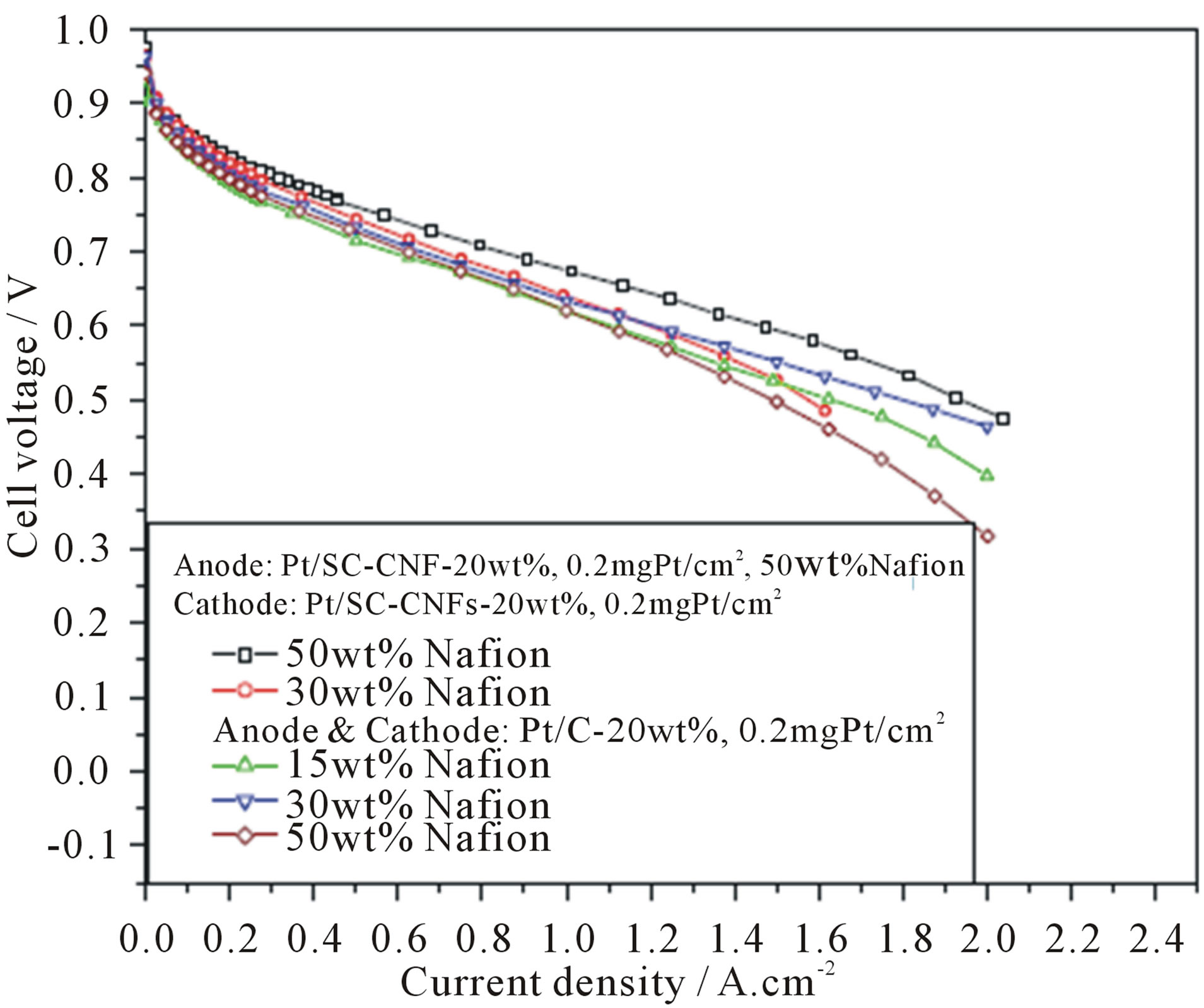
Figure 20. PEMFC polarization curves of MEAs with Pt/C (BASF-Fuel Cell, 20 wt%) or Pt/SC-CNFs (home-made, 20 wt%) with different Nafion amount in the cathode. Test conditions: cell: 70˚C, 100% relative humidity; anode/cathode: H2/O2, 200/200 mL/min, 35/35 psi [109].
the commercial Vulcan XC-72R .The achieved performance of the MEA prepared by e-CNF was excellent in comparison by XC-72R, owing to the characteristics of the morphology and the enhanced electrical conductivity. Figure 21 presents a schematic diagram of the fabrication process of the membrane electrode assembly (MEA), showing Pt penetration on XC-72R and e-CNF. The XC-72R had a morphology giving low Pt utilization as it was tough for the ionomer to form a three-phase boundary with Pt particles entering the mesopores, whereas the e-CNF had a good Pt-supported morphology by presenting a high surface area and shallow pores with enhanced roughness due to the electrospinning and carbonization. The Pt utilization of Pt/e-CNF was 69%, whilst that of Pt/XC-72R was 35% as shown in Figure 22.
More recently, selective CNF growth on one side of the carbon paper for use in proton exchange membrane fuel cells as a gas diffusion layer has been developed [75,110]. It is believed that the direct growth of CNFs on the carbon paper introduces a stronger binding with the carbon paper fibers and the CNF detachment can be avoided [98,111,112]. Particularly, the growth of CNFs directly on carbon paper as catalyst support has shown unique advantage to improve Pt utilization because of their three-dimensional (3-D) structure [74,86,113]. In addition, a better control of the gas diffusion layer structure can be gained by growing the CNFs directly on the carbon paper. In some previously reported studies, CNF growth took place throughout the carbon paper [111,112, 114]. In a wet chemical Pt deposition on CNFs, this results into a Pt deposition throughout the carbon paper, increasing the electronic path and reducing the rate

Figure 21. Schematic diagrams of the fabrication process of the membrane electrode assembly (MEA) (a) Pt/XC-72R and (b) Pt/e-CNF [107].
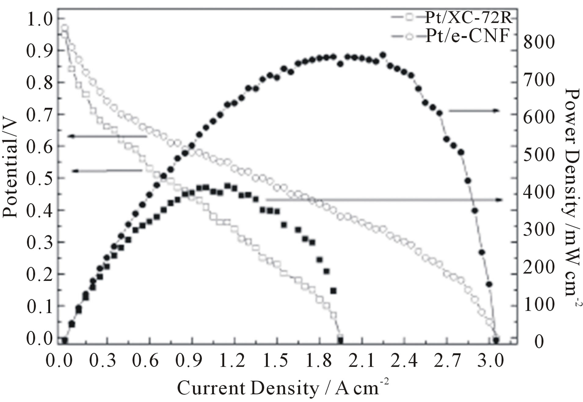
Figure 22. Polarization curves and power density of MEAs with XC-72R and e-CNF [107].
of proton access and thus the Pt utilization [115]. But selective CNF growth on one side of the carbon paper presents a more attractive alternative over the previously reported studies which broadly discussed by Celebi et al. [110].
A novel catalyst structure comprised of Pt catalyst nanoparticles deposited on a preformed 3D CNT network (buckypaper) in order to improving the performance of CNT-based electrode was reported by some researchers. Buckypapers, freestanding thin membranes formed with controlled and dispersed porous network of carbon nanotubes (CNTs), was first proposed in 1998 [116]. Buckypaper is a very useful platform to harvest the exceptional properties of nanotubes. Buckypapers are free-standing thin films consisting of single-walled carbon nanotubes (SWNTs), multi-walled carbon nanotubes (MWNTs) and/or carbon nanofibers (CNFs) held together by vander Waals forces without any chemical binders. The microstructure of buckypaper, e.g. porosity, pore size and thickness, can be tailored by using nanotubes of different diameters and lengths in order to provide sufficient gas diffusion and electron transport path. Therefore, the mass transport resistance of cathodes would be greatly improved. Zhu and coworkers [117] established Platinum catalytic electrode by using carbon nanotube films (buckypaper) as supporting medium and electrodeposition method to deposit Pt catalyst. The mixtures of single walled carbon nanotubes (SWNTs) and carbon nanofibers (CNFs) at the desired ratios (described as SF13 for weight ratio of 1:3 and SF15 for weight ratio of 1:5) were used to prepare the mixed buckypapers to realize larger pore size and porosity, compared to the pure SWNT buckypapers. Figure 23 shows SEM images of the surface morphology of the buckypapers. The permeability testing results indicated that the larger average pore size and higher porosity can result in higher gas permeability. This unique microstructure led to improve Pt catalyst accessibility and mass exchange properties. Pt particles of about 6 nm were homogeneously deposited in porous buckypapers. A promising electrochemical surface area of ~40 m2/g was obtained from these electrodes. A Pt utilization as low as 0.28 g Pt/kW was achieved for the cathode electrode at 80˚C. Figure 24 shows the electrocatalytic activity of the buckypaper-supported Pt catalyst evaluation using cyclic voltammetry in the electrolyte of 0.5 M H2SO4 and the single cell performance (I-V curve) and electrode over potential for the cells using the Pt/ SF13 (cell I) and the Pt/SF15 (cell II) as the cathode respectively.
4. Stability/Durability of CNTs and CNFs-Based Fuel Cell Electrodes
Understanding the long-term stability of the PEM fuel cell is of crucial importance as this technology approaches its commercialization platform. So far, the operational lifetime for real life applications does not satisfy the requirements for state-of-the-art technologies, e.g., 5000 h for cars, 20,000 h for buses, and 40,000 h for stationary applications [118]. Therefore, performance degradation of PEM fuel cells and the degradation of the component materials have attracted extensive attention in recent years. In the past few years, numerous papers have been published that focus on the degradation issues of PEM fuel
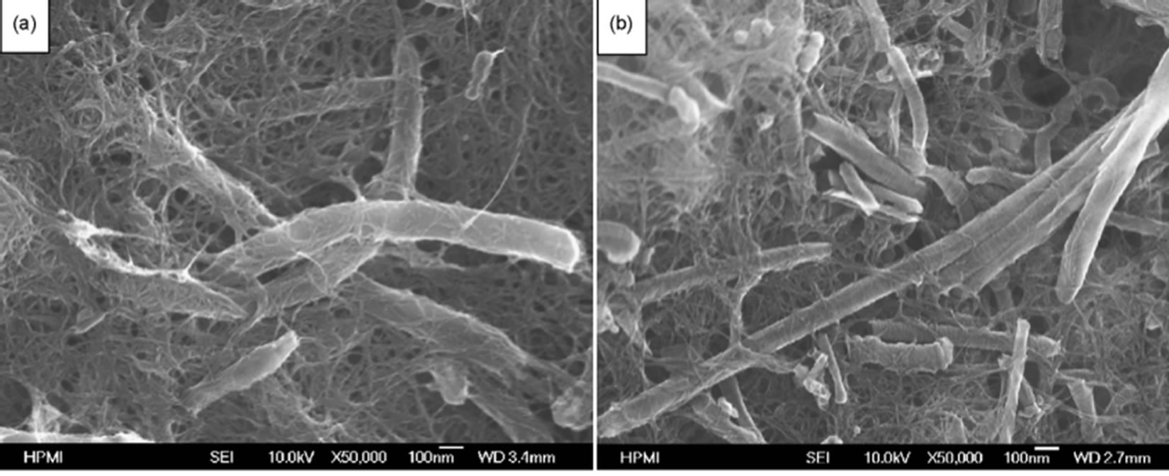
Figure 23. Surface morphology of buckypaper from (a) SF13 and (b) SF15 [117].
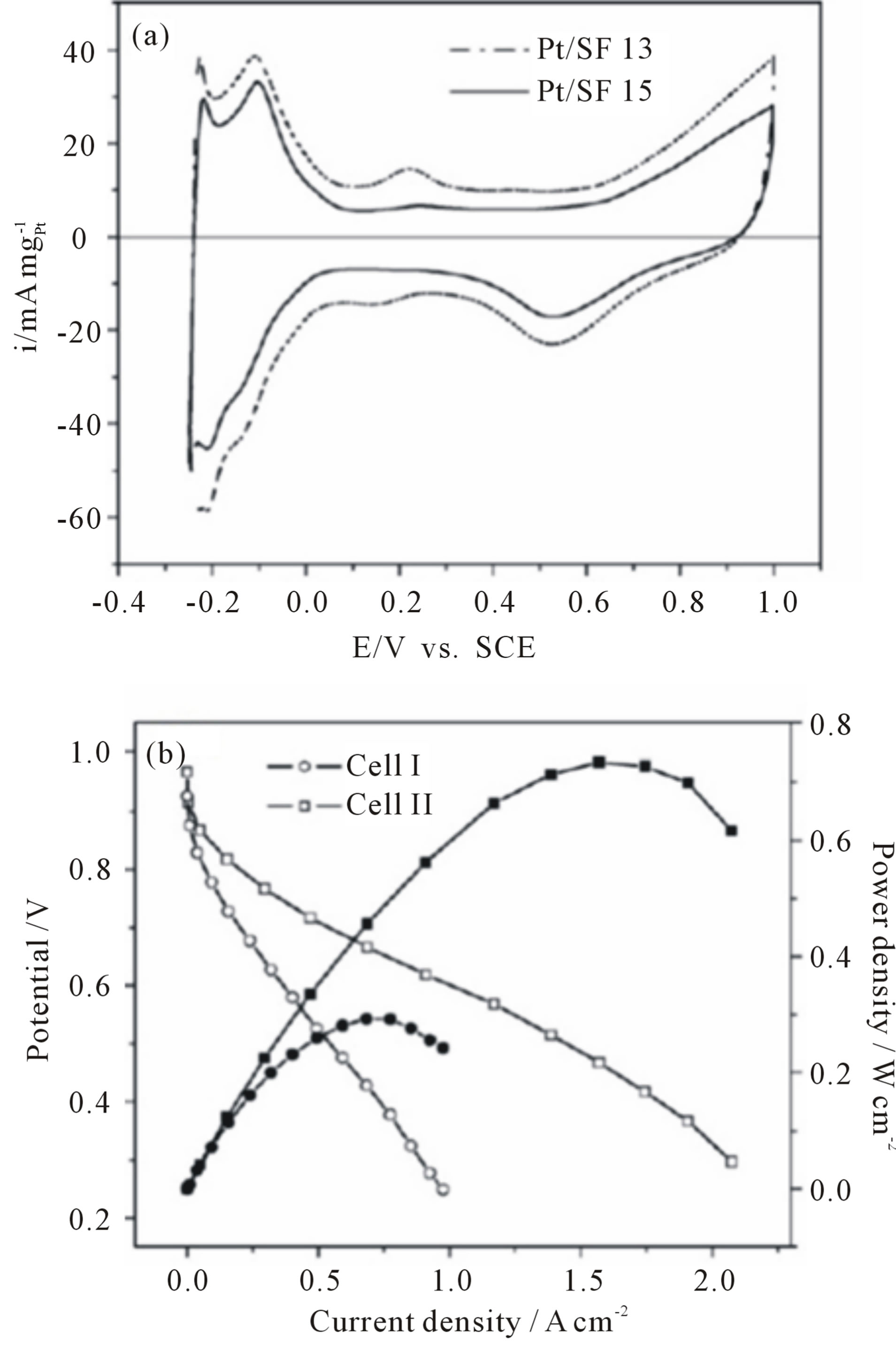
Figure 24. (a) Cyclic voltammograms of buckypaper-supported Pt catalysts in N2-saturated 0.5 M H2SO4 at a scan rate of 50 mV/s and (b) Cell polarization curves and electrode overpotential as a function of current density at 80˚C for cell I and cell II with humidified H2/O2 as the fuel/oxidant at a back pressure of 20 psi [117].
cells. These research progresses on PEM fuel cell durability and degradation have been reviewed from many different perspectives. The review of Borup et al. [119] concentrated on the fundamental aspects of PEM fuel cell degradation mechanisms. Shao et al. [5] and Zhang et al. [120] paid attention to the material challenges to developing durable high temperature PEM fuel cells, including electrocatalysts, carbon supports, membranes, polymers, and bipolar plates. While in Wu et al. review [118], the existing strategies for improving the lifetime of the fuel cell components were summarized. It has been found that the degradation of the fuel cell performance is primarily due to the decay of the membrane-electrodeassembly (MEA) [121-123]. Among the MEA components, catalyst layer or electrocatalyst degradation is one of the most critical factors and increasing catalyst layer or electrocatalyst durability is a major challenge and a growing focus of research attention in PEM fuel cell durability studies.
5. Accelerated Lifetime Tests
Until now, while extensive studies have been carried out to understand the degradation mechanisms of fuel cell components such as electrocatalysts, membranes, and other parts, only a relatively small number of studies aimed at real PEM fuel cell lifetimes have been conducted, due to the high costs and elongated testing periods mandatory. For example, more than 4.5 years of uninterrupted testing is needed to reach the 40,000 h lifetime requirement for a fuel cell system for stationary applications. For testing a fuel cell bus system (275 kW) for 20,000 h, the fuel expense alone would be approximately US $2 million (3.8 billion liters of hydrogen at US $5.3 m−3). Therefore, the so-called accelerated degradation test (ADT) is developed [124-126], in which the electrocatalysts were held at a constant potential or potential cycling for a certain time scale under a simulated PEM fuel cell condition, and then the degraded electrocatalysts were analyzed to obtain the detailed information to clarify the nature of the degradation [119,127]. Even though, to test the durability of electrocatalysts usually takes about 100 - 200 h, especially for studying the durability of catalyst support materials [118]. To date, several different accelerated parameters or a combination of these parameters have been employed in accelerated life testing. Primary 3 methods are used to age electrocatalysts and each addresses different failure modes. The first method is an ex situ thermal aging technique that measures support stability [128]. In this method, catalyst powder is weighed and placed in an oven. The weight loss of the powder is monitored over time (Figure 25(a)). This technique studies the stability of the support to platinumcatalyzed chemical combustion and is very useful for determining the relative stability of different carbon supports. The second method is an in situ technique to measure the electrochemical stability of the support at a given potential. In this test, an MEA is typically held at approximately 1.0 V under H2/N2. Periodically, the surface area is measured via cyclic voltammetry and the change in surface area over time is recorded as a measure of the catalyst stability (Figure 25(b)). The time border to observe a loss in surface area greatly depends on the carbon type and cell voltage. Typically, the higher the carbon support surface area or the higher the cell voltage, the easier to age the support and observe a change in surface area. The last method, potential cycling, is the most complex to analyze as it accelerates electrochemical degradation of the support, platinum agglomeration, and platinum dissolution. The potential cycle is typically from 0.05 to 1.0 or 1.2 V with the cell under H2/N2 gas feeds. The potential cycle causes the most damage to the catalyst because it accelerates three degradation pathways. Typically, a rapid decrease in catalyst surface area is observed (Figure 25(c)). Among the various aspects of MEA degradation, a decrease in the electrochemical surface area (ESA) of the cathode catalyst has attracted attention as a criterion for the degree of degradation [129-132].
Most of the methods relied on the traditional carbon support. Only a few publications are available regarding durability investigation of CNTs as a catalyst support for PEM fuel cells [4,77,124]. for example Wang et al. compared the electrochemical surface oxidation of carbon black Vulcan XC-72 and multiwalled carbon nanotube (MWNT) following potentiostatic treatments up to 168 h under condition simulating PEMFC cathode environment (60˚C, N2 purged 0.5 MH2SO4, and a constant potential of 0.9 V). The subsequent electrochemical characterization at different treatment time intervals suggests that MWNT is electrochemically more stable than Vulcan XC-72 with less surface oxide formation and 30% lower corrosion current under the investigated condition. As a result of high corrosion resistance, MWNT shows lower loss of Pt surface area and oxygen reduction reaction activity when used as fuel cell catalyst support [77]. Their
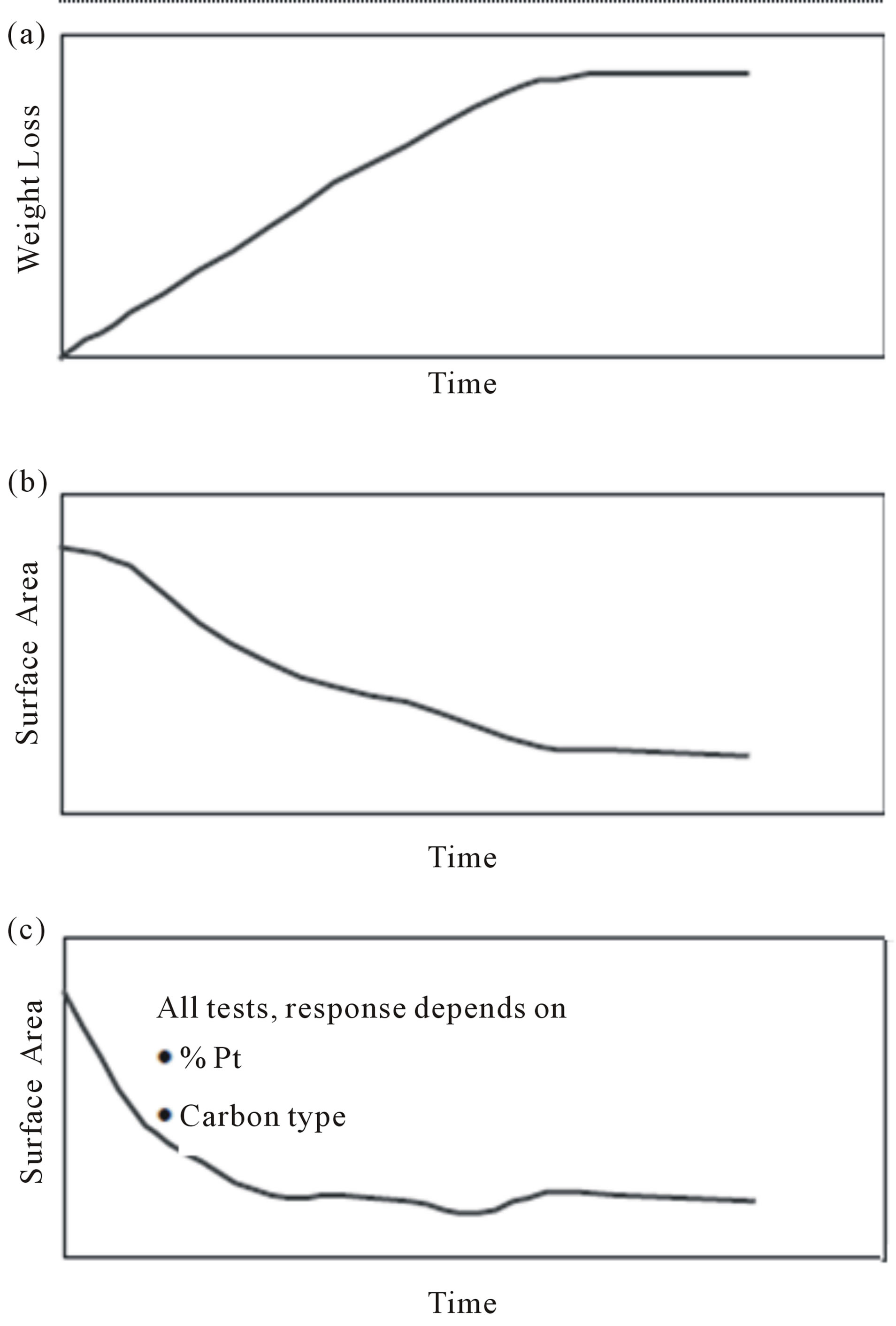
Figure 25. Examples of catalyst screening tests. Typical results from (a) thermal aging, (b) constant potential aging, and (c) potential cycling [128].
result of Pt surface area loss with experimental time is as shown in Figure 26. It can be seen that almost 80% of Pt surface area was lost for Vulcan XC-72 after 168 h oxidation treatment, while only 37% loss is observed for MWNT. Furthermore, most of the surface area loss for the case of MWNT occurs within 72 h, and after 72 h the rate for the Pt area loss is very small, indicating that MWNT could potentially provide much higher durability than Vulcan XC-72.
In respect to stability of CNFs, electrochemical surface oxidation of raw and functionalized carbon nanofibers, and carbon black for comparison, was studied following a potential step treatment at 25.0˚C in acid electrolyte by Álvarez et al. [133]. Surface oxidation was characterized using cyclic voltammetry, X-ray photoelectron spectroscopy (XPS), and contact angle measurements. The relative increase in surface oxides on carbon nanofibers during the electrochemical oxidation treatment was significantly smaller than that on carbon black. This suggested that carbon nanofibers are more resistant to the electrochemical corrosion than carbon black under the used experimental conditions. Cyclic voltammetry of studied
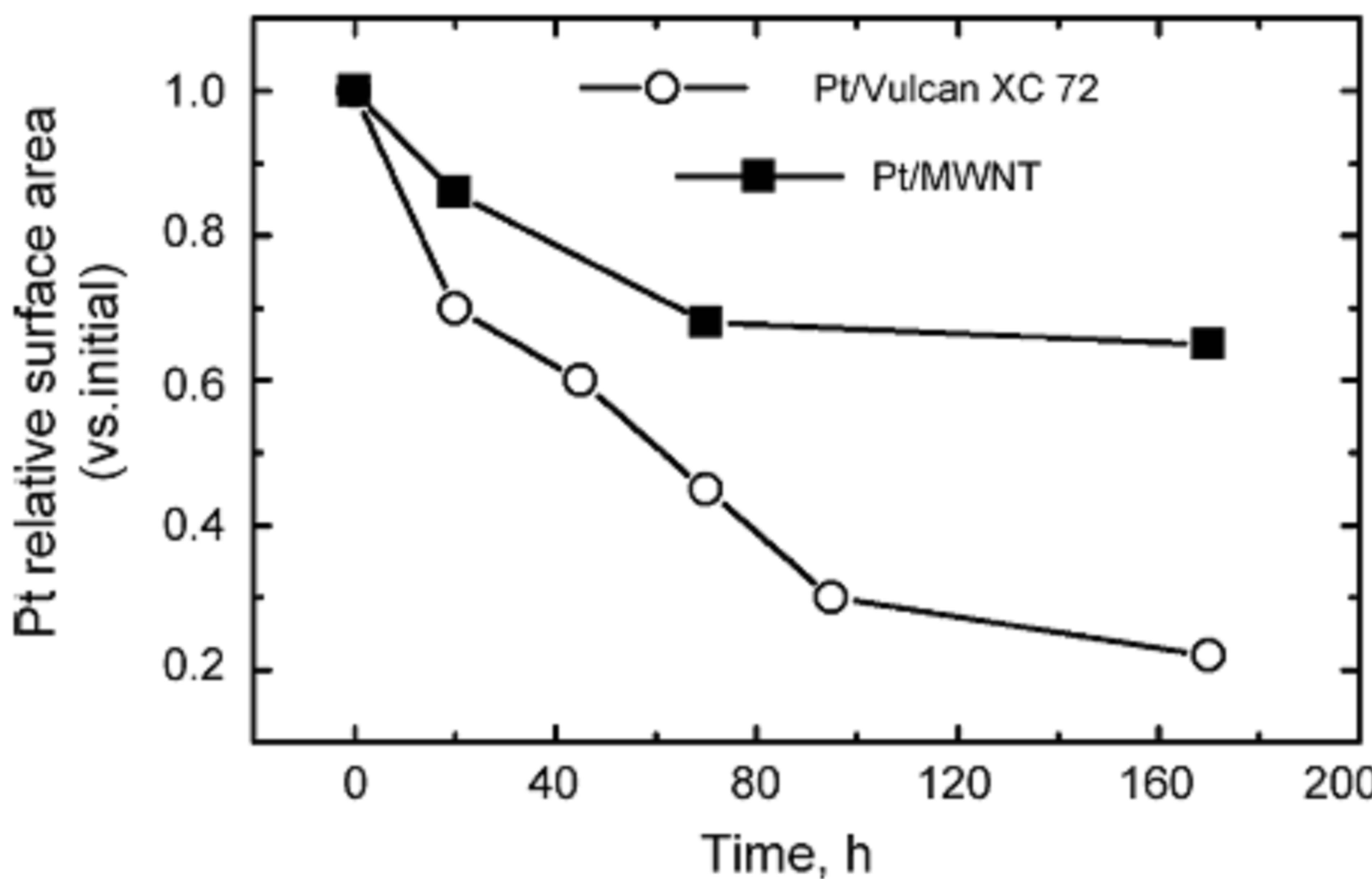
Figure 26. Comparison of Pt active surface area loss for the case of Vulcan XC-72 and MWNT at different time intervals during oxidation treatment [77].
supports at recorded after potential step cycling at different times in 0.50 mol/dm3 H2SO4 at 25.0˚C are shown in Figure 27. Based on the good results the authors concluded that carbon nanofibers possess a high potential as catalyst support to increase the durability of catalysts used in low temperature PEMFC applications.
Moreover Santasalo-Aarnio et al. [134] investigated the durability of different carbon nanomaterial supports i.e. Vulcan, graphitized carbon nanofibers (GNF) and few-walled carbon nanotubes (FWCNT) with PtRu catalyst and their performance for methanol oxidation was studied in an electrochemical cell and in a single cell DMFC. The electrochemical results indicated that with PtRu/GNF and PtRu/FWCNT higher current densities was obtained and oxidation intermediates deactivate the surface less compared to the same catalyst on Vulcan support. Conversely, PtRu/Vulcan provided the highest open circuit voltage OCV and current densities in DMFC experiments due to a well-optimized electrode layer structure in order to assessment the stability of supports 6-day-long fuel cell stability tests were carried out, showing that PtRu/Vulcan degraded significantly. This attributed to the collapse of the secondary structure of the electrode layer revealed by post characterization of the membrane electrode assembly (MEA) with SEM and TEM. PtRu/GNF exhibited slightly poorer initial performance but better stability because the structure of the anode layer was maintained. PtRu/FWCNT showed the worst initial performance and long-term stability. Figure 28 shows the chronoamperometric experiments that have been performed at 0.7 V.
6. Carbon Nanohorn-Supported Electrocatalyst for PEM Fuel Cell
The effect of nanohorn as another candidate of carbon support for fuel cell applications has only been studied to a very limited extent. Yoshitake et al. synthesized singlewall carbon nanohorns (SWNH) as the support in PEM fuel cell cathode preparation [38]. The SWHN is a kind of carbon nanotube with a horn-shaped sheath of single wall graphene sheets. The Pt catalyst was supported on the SWNHs by colloidal method. In the preparation, NaHSO3 and H2O2 were added into an H2PtCl6 solution to form Pt oxide colloids. Then the SWNH powder was added into the Pt oxide colloid solution where the Pt oxide colloid was adsorbed on the SWNH surface. After eliminating Cl, Na and S ions, the samples were submitted to drying and then reduced by H2 gas. The produced Pt/SWNH catalyst showed very homogeneous dispersion of Pt nanoparticles with an average size of 2 nm. The loading of Pt nanoparticle dispersion on the surface of SWNH was less than half of that supported on the conventional carbon black (Vulcan XC-72). The improvement of the fuel cell performance may be attributed to the homogenously dispersed small-sized Pt particle on the SWNH.
Moreover Kosaka et al. [135] reported high-power direct methanol fuel cells (DMFCs) by using single-wall carbon nanohorns (SWNHs) to support the Pt catalyst for the DMFC cathode used for mobile power applications. The unique structure of the SWNH aggregate was beneficial to support the fine Pt catalysts. To prevent the growth of Pt particles even under high-Pt-content conditions, defects were deliberately created on the surface of SWNHs by oxidizing them with H2O2. This reduced the mean diameter of the Pt particles supported on the SWNHs to 2.9 nm, which is roughly 2/3 that of the Pt particles on as grown SWNHs, for 60 wt% Pt content. They also improved the process used to make a MEA by immersing the catalyst electrodes in 50 vol% MeOH before the hot-pressing process. This increased the active surface area of the Pt catalysts to nearly 100% of the Pt surface and strengthened the joint between the electrodes and the membrane. Figure 29 a shows the Cyclic voltammograms for 50 wt% Pt on as-SWNHs catalyst electrodes that immersed in 50 vol% MeOH solution for various times. These improvements enabled them to obtain a power density of 76 mW/cm2 at 0.4 V for a passive-type DMFC operated at 40˚C. The current-voltage (I-V) characteristics at 40˚C of passive-type DMFC test cells (using 4 vol% MeOH as fuel and air as oxidant) with MEAs whose electrodes had been immersed in 50 vol% MeOH for 0 to 18 h was shown in Figure 29.
7. Carbon Nanocoils (CNCs)-Supported Pt-Based Electrocatalysts: Electrochemical Activity and Performance in Single Cell
Recently, carbon nanocoils (CNCs), a new nanostructured carbon support used as DMFC catalyst supports [136,137]. The researchers prepared Pt-Ru/CNC and
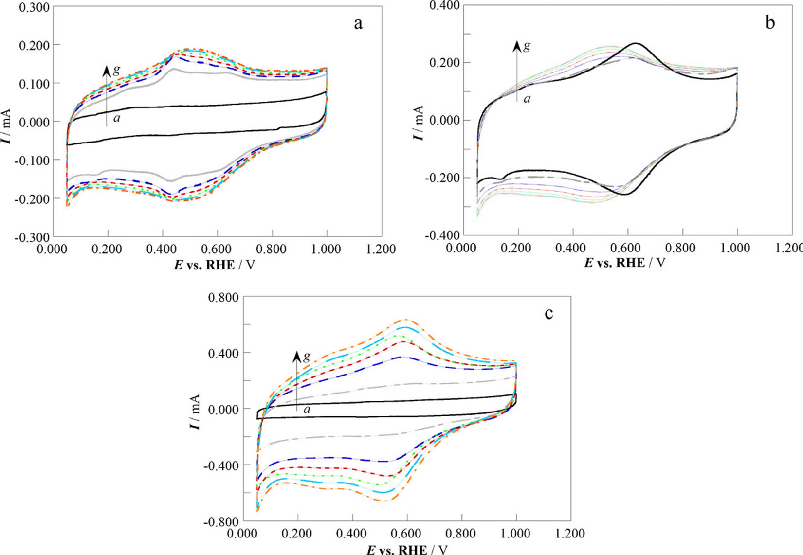
Figure 27. Cyclic voltammograms of carbon supports: (a) CNF, (b) CNF-f, and (c) CB, recorded after potential step cycling at different times in 0.50 mol dm−3 H2SO4 at 25.0˚C: (a) 0 h, (b) 1 h, (c) 5 h, (d) 10 h, (e) 15 h, (f) 20 h, and (g) 24 h [133].

Figure 28. Methanol oxidation on PtRu catalyst on different carbon supports in 0.1 M HClO4 and 1 M methanol solutions. chronoamperometric curves at 0.7 V potential. (a) PtRu/Vulcan (black line), (b) PtRu/FWCNT (red line), (c) PtRu/GNF (green line) [134].
Pt-Ru/Vulcan XC-72 catalysts with 60 wt% metal loading, and compared their performance to commercially available E-TEK Pt-Ru/C catalyst for DMFCs. They found that, under identical testing conditions, the current density at 0.6 V catalyzed by a CNC-supported catalyst was 4 and 20 times higher, and the maximum power density was 170% and 230% higher than that of Vulcan supported catalyst and the commercial catalyst, respectively (Figure 30). The excellent performance was attributed to the low electric resistance and the unique pore characteristics of CNCs, which favour the diffusion of methanol and the removal of CO2 gas. The CNC-supported catalyst exhibited a substantially higher specific oxidation current of 80 A/g at 0.4 V (versus NHE) near the kinetically controlled potential in the methanol reaction, compared to 20 A/g for the Vulcan XC-72 supported catalyst and 14 A/g for the E-TEK supported catalyst.
8. Pt and Pt-Based Materials Deposition on Graphene Nanostructure and Its Electrocatalytic Property and Morphology
The recent advent of graphene nanoelectronics has opened a new avenue for utilizing 2-dimensional carbon material as a support in PEM fuel cells. The 2-D planar structure of the carbon sheet allows both the edge planes and basal planes to interact with the catalyst nanoparticles. The rippled but planar sheet structure also provides a very high surface area for the attaching catalyst nanoparticles. One hopes to employ such 2-D sheets as conductive mats to both anchor electrocatalysts and modulate the electrochemical reactions in a controlled manner. Shao et al. [138] reported graphene nanoplatelets (GNPs), which exhibit the advantages of both single-layer graphene and highly graphitic carbon, as a durable alternative support material for Pt nanoparticles for oxygen re
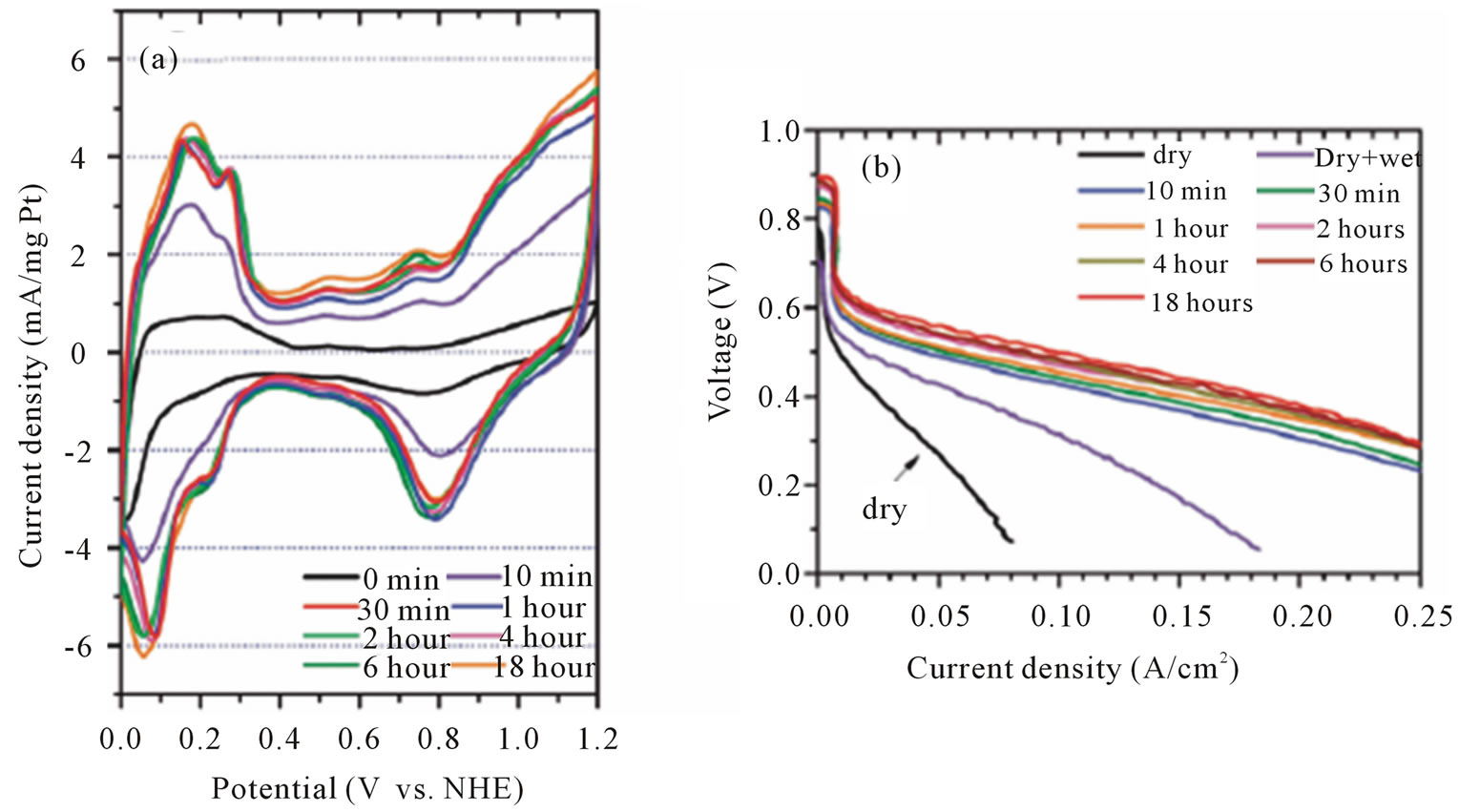
Figure 29. (a) Cyclic voltammograms for 50 wt % Pt on as-SWNHs catalyst electrode that immersed in 50 vol% MeOH solution for various times; (b) I-V characteristics of MEA whose catalyst electrodes were immersed in a 50 vol% MeOH solution for 0 to 18 h prior to the hot pressing [135].

Figure 30. (a) Specific methanol electrooxidation current (S.C.) with respect to applied potentials (versus NHE) of a Pt/Ru (1:1) alloy catalyst (60 wt%) supported on carbon nanocoils (CNC), Vulcan XC-72, and a commercial supported catalyst at 25C; (b) Polarization curves for a DMFC using a Pt-Ru catalyst (60 wt%) supported on carbon nanocoils (CNC), Vulcan XC-72 and a commercially available supported catalyst. CV, CD and PD stand for cell voltage, current density, and power density, respectively [137].
duction in fuel cells. Pt/GNP exhibited significantly enhanced electrochemical durability (2 - 3 times that of Pt/CNT and commercial Etek Pt/C). Liu et al. [139] fabricated Nanocomposite films of platinum nanoparticledeposited expandable graphene sheet (Pt/EGS) on conductive indium tin oxide glass electrodes via a “green” electrochemical synthetic route involving a series of electrochemical processes. The as-synthesized Pt/EGS nanocomposite exhibited high catalytic activity and good stability for the oxidation of methanol, which may be attributed to its excellent electrical conductivity and the high specific surface area of the graphene sheet catalyst support.
Application of graphene have been extensively investigated as catalysts carrier especially in methanol oxidation and oxygen reduction in recent years and the catalytic performance indicated the grapheme supported Pt electrocatalyst had good catalytic activity in their applications. For example Li and coworkers [140] prepared the composites of graphene nanosheets decorated by Pt nano clusters via reduction of graphite oxide and H2PtCl6 by impregnation method. To evaluate the activity of the Pt/graphene catalysts toward the methanol electrooxidation, cyclic voltammogram experiments were tested in the solution of 0.5 M CH3OH in 0.5 M H2SO4. Additionally the catalytic stability of the Pt/graphene and Pt/Vulcan were examined using chronoamperometry. The results were shown in Figure 31. As can be seen from these figures the composites have superior catalytic performance toward methanol oxidation indicating the
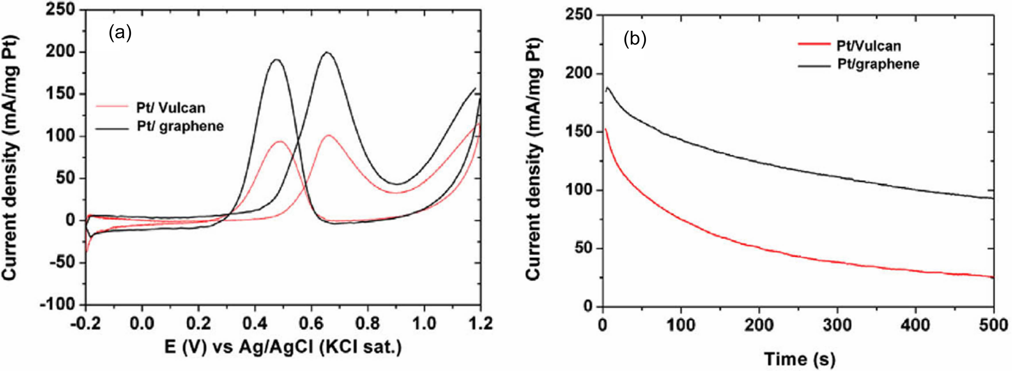
Figure 31. (a) Cyclic voltammograms of Pt/graphene and Pt/Vulcan in nitrogen saturated aqueous solution of 0.5 M H2SO4 containing 0.5 M CH3OH at a scan rate of 50 mV s/1; (b) Chronoamperometric curves for Pt/graphene and Pt/Vulcan catalysts in nitrogen saturated aqueous solution of 0.5 M H2SO4 containing 0.5 M CH3OH at a fixed potential of 0.6 V vs. Ag/AgCl (KCl sat.) [140].
graphene may have an impressive future as catalysts carrier in electrocatalysis and fuel cell.
Shao et al. [141] reported a durable electrocatalyst with graphene nanoplatelets (GNPs) as the support, which exhibits 2 - 3 times durability of commercial Etek Pt/C and Pt/CNT catalysts toward oxygen reduction reaction (ORR). In their experiments graphene nanoplatelets were synthesized by exfoliating the sulfuric acidbased intercalated graphite using a microwave oven followed by ultrasonication and milling. It created GNP of 5 - 10 nm in thickness with a specific surface of 100 m2/g. Pt/GNP electrocatalyst was prepared with ethylene glycol (EG) reduction method. Figure 32 shows the TEM images and Pt nanoparticle distribution of Pt/GNP, Pt/ CNT, and commercial Etek Pt/C. Figure 33 shows the durability of Pt/CNT, Etek Pt/C and Pt/GNP which were characterized with the retaining percentage of the ESA and ORR after the degradation test (44 h). Under the same accelerated degradation test (ADT) condition which has been shown to effectively study the catalyst durability with the emphasis on support corrosion [86], Pt/CNT and Etek Pt/C degraded by ~75% (ESA and ORR), but only ~40% (ESA) and ~20% (ORR) for Pt/GNP, i.e., the degradation rate for Pt/CNT and Etek Pt/C is 2 - 3 times that of Pt/GNP. These are attributed to the intrinsic high graphitization degree of GNP and the enhanced Pt-carbon interaction in Pt/GNP. By considering that GNP can be easily mass produced from graphite they proposed that GNP is a promising, low-cost, and durable electrocatalyst support for oxygen reduction in fuel cells.
Fabrication and Performance of Graphen-Platinium Nanocomposite Membrane Electrode Assembly
In the polarization curve measurement in a PEM fuel cell that conducted by Seger and Kamat [142] with reduced graphene-oxide-Pt catalyst the role of graphene as an effective support material in the development of an electrocatalyst has been proved. They constructed proton exchange membrane assemblies using different electrocatalysts deposited on toray paper as the cathode and Pt-dispersed on carbon black (E-Tek CB-Pt) as the anode. The performances of these assemblies in a hydrogen fuel cell are compared in Figure 34. An unsupported Pt cathode was used as a reference to compare the performance of reduced graphene oxide supported Pt electrocatalysts. According their results both catalyst assemblies produced similar open-circuit voltage but the voltage drop varied as we drew the current from the cell. The partially reduced GOPt based fuel cell delivered a maximum power of 161 mW/cm2 compared to 96 mW/cm2 for an unsupported Pt based fuel cell. The dispersion of the electrocatalyst on graphene has been found to be useful for achieving relatively better performance in fuel cells.
9. Carbon Aerogel-Supported Pt-Based Electrocatalysts: Electrochemical Activity and Performance in Single Cell
Recently, carbon aerogels have been used as catalyst supports for fuel cell applications. Carbon aerogels have fundamental properties such as high conductivity, high mesoporosity, a relatively small degree of microporosity, and high surface area that potentially make them more suitable electrocatalyst supports than carbon blacks. Pore structure in fuel cell electrodes affects mass transportation of fuel and exhaust, and then affects cell performance vitally [143]. The advantages of carbon aerogel may be attributed to the mesopore structure that can facilitate the mass transportation in the electrode.
Anderson et al. [144] developed highly active electrocatalytic nanostructured architectures constructed from carbon-silica composite aerogels in which the carbon was
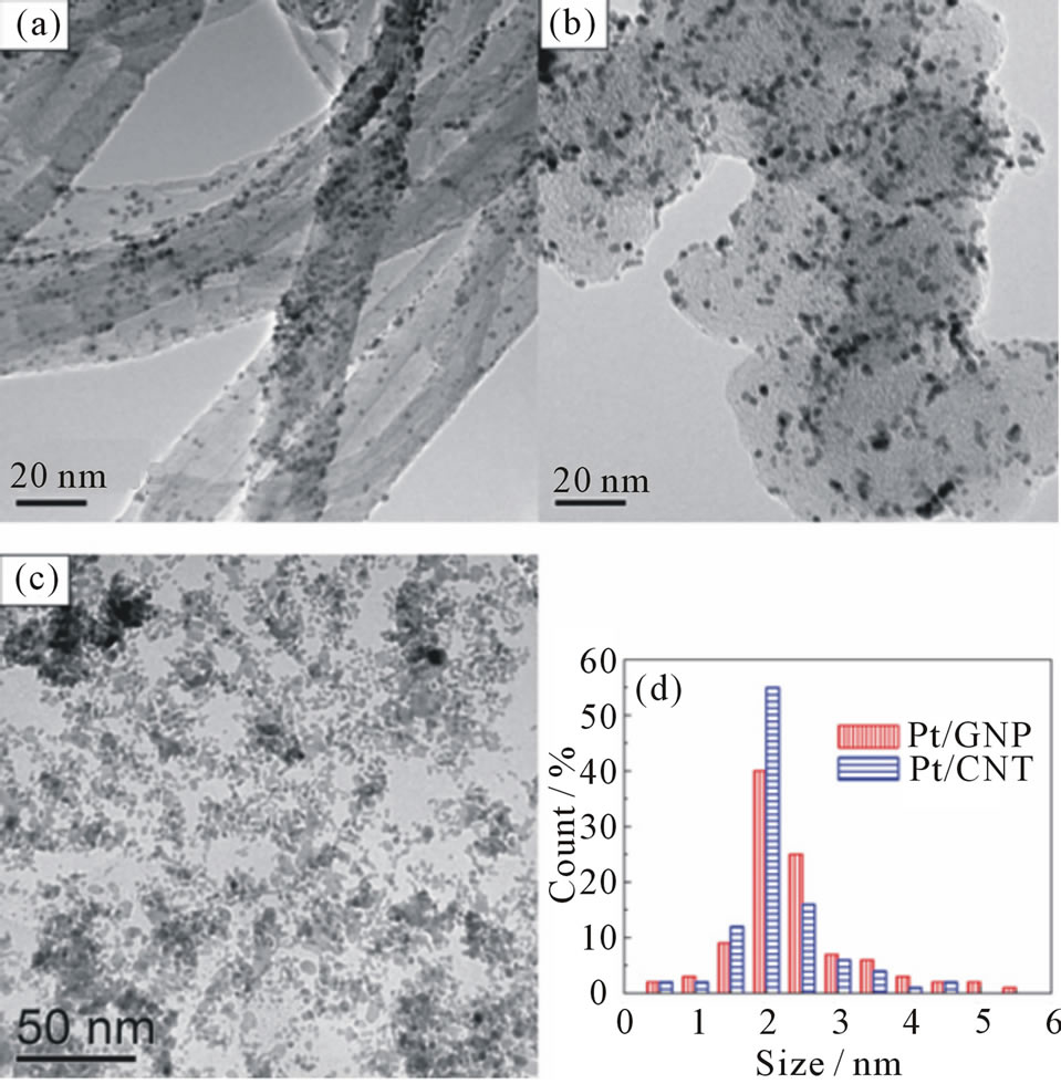
Figure 32. TEM images of Pt/CNT (a), Etek Pt/C (b) and Pt/GNP (c), and Pt nanoparticle distribution of Pt/CNT and Pt/GNP (d) [141].

Figure 33. the percentage of the retaining ESA and ORR activity on Pt/GNP, Pt/CNT, and Etek Pt/C electrodes after the degradation (44 h) [141].
modified with nanoscopic electrocatalysts. According to their paper the electrocatalytic activity for methanol oxidation at colloidal-Pt-modified carbon-silica composite aerogels increased by 4 orders of magnitude per gram of Pt over that at native Pt-modified carbon powder.
Glora et al. [145] prepared fiber reinforced carbon aerogel and integrated the function of support and diffusion layer of PEMFC. The integration reduced the internal resistance very much. However, the application of carbon aerogel in DMFCs was seldom reported. Marie et al. [146] prepared a platinum loaded carbon aerogel catalyst for PEMFC electrodes by an impregnation method. The catalyst exhibited high specific activity for oxygen
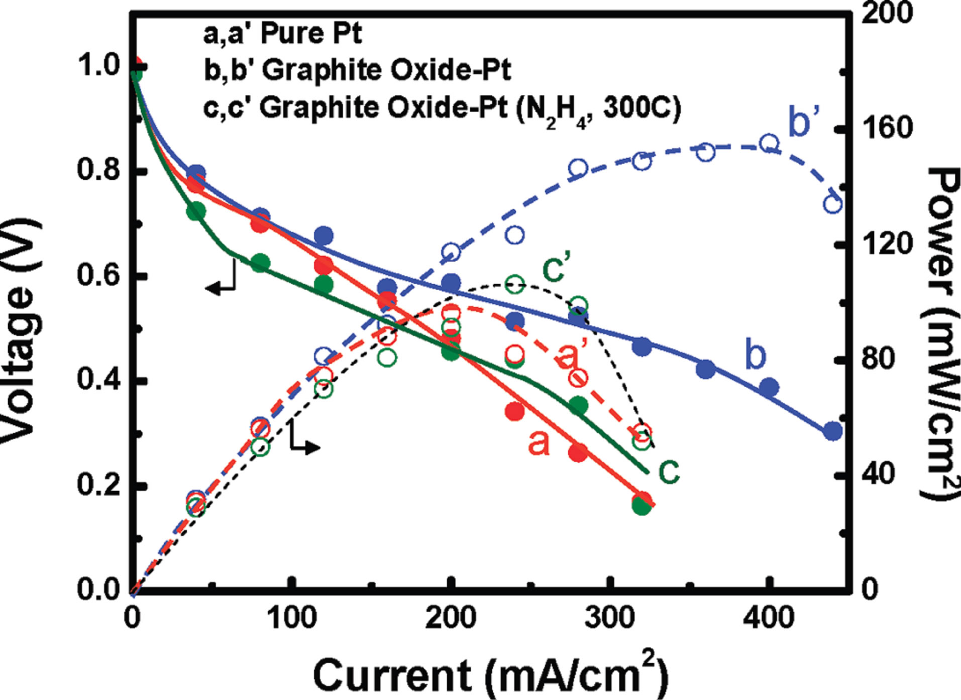
Figure 34. Galvanostatic fuel cell polarization (I-V) curves (a, b, c) and power characteristics (a', b', c') of a fuel cell at 60˚C and 1 atm of back pressure. The cathode was composed of (a, a') Pt, (b, b') 1:1 GO-Pt, and 1:1 GO-Pt (hydrazine, 300˚C treated). Electrocatalyst concentration was maintained at 0.2 mg/cm2 Pt. The anode for all experiments consisted of 0.5 mg/cm2 Pt of E-Tek CB-Pt. The anode and cathode catalyst films were heat pressed on Nafion 115 membrane [142].
reduction reaction compared with Pt-loaded carbon blacks. Smirnova et al. [147] prepared Pt/CAGs catalysts with various metal loadings and studied the electrochemical surface area and single cell performance for oxygen reduction under different operating conditions. Pt/CAGs showed a better catalytic performance and higher open circuit voltage than the commercial catalyst. Furthermore, its Tafel slope was close to the theoretical value, and the electrochemical surface area was two times that of the commercial catalyst. The catalyst supported on CAGs (pore size of 20 nm) with low Pt loading (0.1 mg/cm2) showed a maximum power density close to 0.8 mW/cm2 in air at ambient pressure. This was possibly due to the better penetration of Nafion particles into the pores of the aerogel carbon support and better coverage of the membrane surface with the lower Pt content catalyst. Kim et al. [148] synthesized platinum-carbon aerogel catalysts from the alcoholic solgel reaction of phloroglucinol with furfural using propylene oxide as a reducing agent of platinum salt, followed by supercritical drying with carbon dioxide. Subsequent carbonization of platinum-organic aerogels under a reducing gas flow produced platinum-carbon aerogels. X-ray diffraction and transmission electron microscopy analyses of the platinum-carbon aerogel catalysts indicated that the formation of welldispersed platinum nanoparticles having sizes of about 3 nm. The physical and electrochemical properties of the prepared platinum-carbon aerogel catalysts were compared with those of commercial catalysts such as E-TEK, Johnson Matthey (JM), and Tanaka catalyst.
Du and coworkers [149] performed a single cell tests by a carbon aerogel (CA) loaded with Pt-Ru bimetallic nanoparticles when used as a direct methanol fuel cell anode catalyst. They studied the single cell performance in different temperatures. The Ru content in the catalyst has a great influence on its performance. And the PtRu/ CA with 25 at% Ru achieves the best cell performance at 30˚C (Figure 35).
10. Conclusions
Fuel cells have been known for a long time and still are under development. Several challenges to widespread implementation of PEM fuel cell technology are needed, although novel inexpensive and long-term electrocatalysts materials are key factors in design and development. In all fuel cells including low temperature fuel cells, the over potential for the reduction of oxygen at operating currents is significantly high due to the slow oxygen electrochemical kinetics. As a result of this sluggish kinetics, cell voltage decreases and therefore fuel cells lose in efficiency. Therefore the high over potential for oxygen reduction is a foremost problem and, so far, research on the fundamental process of oxygen reduction and catalysis has not yielded a breakthrough by the current fuel cell cathode catalyst. Thus, new alternatives for finding materials with lower over potential are needed. Recent advances in application of nanostructured carbonaceous-based materials have suggested the possibility of using these materials as novel electrocatalysts supports. Studies have shown that Pt nanoparticles supported on nanostructured carbonaceous-based materials display remarkably higher electrocatalytic activity toward the reduction of oxygen than Pt nanoparticles supported on carbon black, which would contribute to substantial cost reduction in PEM fuel cells. The finite size of nanoscale materials positively influences the thermodynamics and kinetics of oxygen reduction due to their length scale and
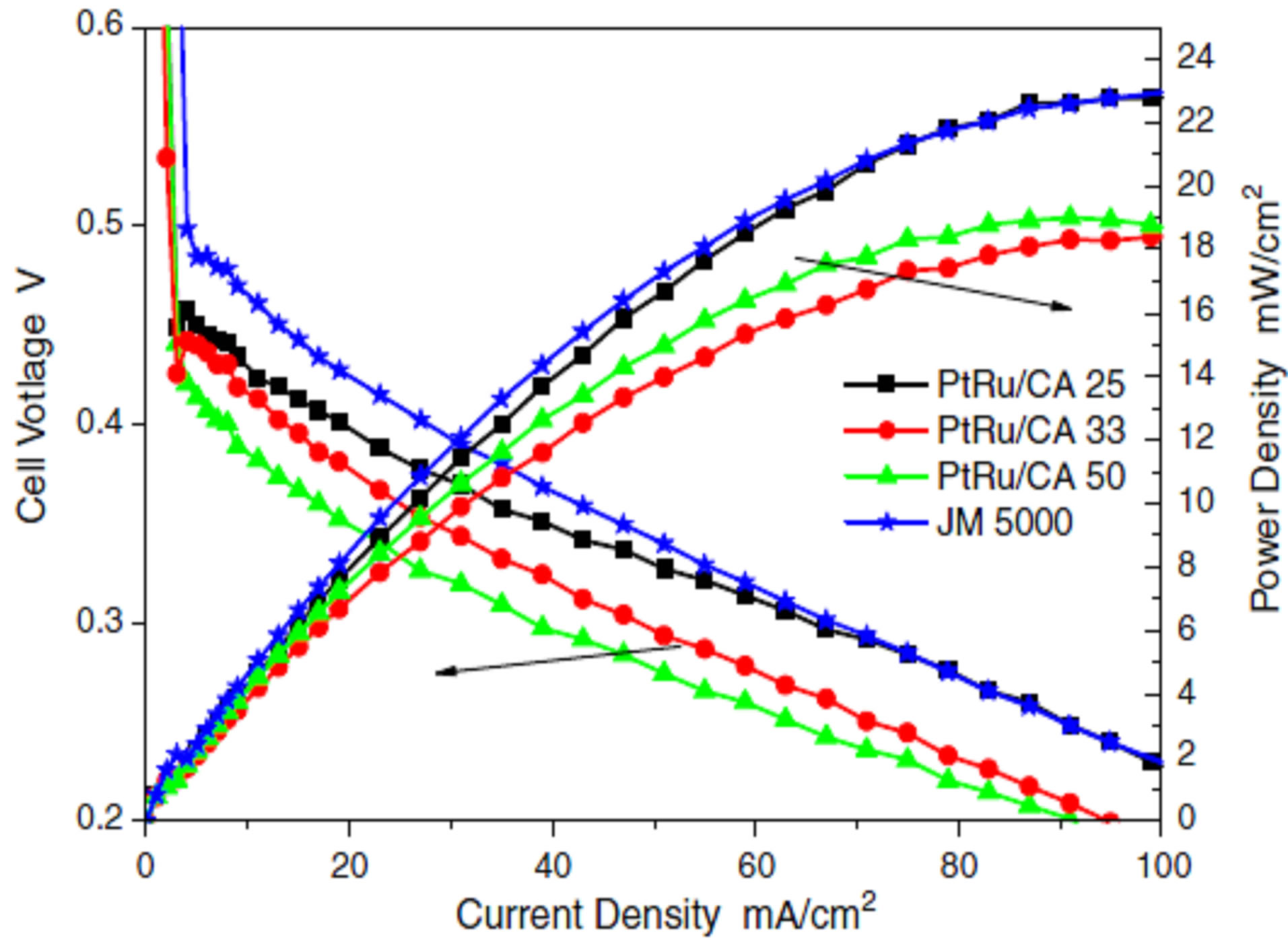
Figure 35. Polarization curves and power density curves of single cell at 30˚C. Methanol flow rate: 10 ml/min; oxygen flow rate: 500 ml/min [149].
specific properties. In general, their unique characteristics encourage the use of nanosize electrocatalysts materials instead of their bulk counterparts to enhance the oxygen electroreduction performance.
This article reviewed various nanostructured catalyst supports including nanostructured materials such as carbon nanotubes, carbon nanofibers, carbon aerogels, nanoplates of graphene, etc. as substitutes of carbon black to improve the performance and durability of electrodes through increasing electrocatalytic activity and Pt utilization. Various preparation methods for active electrocatalyst have been examined with some consideration from practical points of view associated with each preparation method. Types of catalyst supports and their structure (also properties) along with some synthetic strategies for selected support types have been also explored based on the recent literature for low temperature fuel cell application. The paper started by introducing CNT and/or CNF with unique structures and excellent mechanical, thermal and electric properties which have been explored as novel catalyst supports for PEM fuel cell catalyst. For the synthesis of CNT supported by Pt catalyst, several synthesis methods were discussed. These studies have revealed that the morphology and catalytic activity of Pt/CNT and Pt/CNF catalyst are seriously affected by their corresponding synthesis methods. These were all closely related to the utilization and performance of the catalysts in fuel cells. To effective attachment of pt nanoparticles uniformly dispersed onto CNTs or CNFs because of inertness of their surface, the surface oxidation treatment in either strong or mild acids in order to obtain reactive sites for the adhesion of Pt metal particles has been considered. We also discussed about the durability issues of PEM fuel cell by using CNT and CNF based electrode which have been considered as the major barriers to the commercialization of fuel cell. New carbon-based materials like carbon aerogel and graphene nanoplates, one type of novel carbon nanostructures, are also offering new avenues for research during the past several years. A number of research groups have investigated graphene as catalyst support and have demonstrated that the graphene can improve the electrocatalytic activity of Pt nanoparticles more effectively for methanol and ethanol oxidation than Vulcan XC-72R carbon black.
In conclusion, nanotechnology is evident in the recent developments for PEM fuel cells. Whilst much is reported on the preparation of highly-dispersed Pt and Pt-alloy catalyst, it is recognized that improvements can be made to the nanostructured electrocatalysts support. In this context, nanostructured materials such as carbon nanotubes (CNT), carbon nanofibers (CNF), carbon aerogels, nanoplates of graphene, etc. are proved to be better alternatives than the high surface area and conductive carbon black.
REFERENCES
- H. A. Gasteiger, S. S. Kocha, B. Sompalli and F. T. Wagner, “Activity Benchmarks and Requirements for Pt, Pt-Alloy, and Non-Pt Oxygen Reduction Catalysts for PEMFCs,” Applied Catalysis B: Environmental, Vol. 56, No. 1, 2005, pp. 9-35. http://dx.doi.org/10.1016/j.apcatb.2004.06.021
- M. Pourbaix, “Atlas of Electrochemical Equilibria in Aqueous Solutions,” 1974.
- J. Liu, Z. Zhou, X. Zhao, Q. Xin, G. Sun and B. Yi, “Studies on Performance Degradation of a Direct Methanol Fuel Cell (DMFC) in Life Test,” Physical Chemistry Chemical Physics, Vol. 6, No. 1, 2004, pp. 134-137. http://dx.doi.org/10.1039/b313478d
- Y. Shao, G. Yin, J. Zhang and Y. Gao, “Comparative Investigation of the Resistance to Electrochemical Oxidation of Carbon Black and Carbon Nanotubes in Aqueous Sulfuric Acid Solution,” Electrochimica Acta, Vol. 51, No. 26, 2006, pp. 5853-5857. http://dx.doi.org/10.1016/j.electacta.2006.03.021
- Y. Shao, G. Yin, Z. Wang and Y. Gao, “Proton Exchange Membrane Fuel Cell from Low Temperature to High Temperature: Material Challenges,” Journal of Power Sources, Vol. 167, No. 2, 2007, pp. 235-242. http://dx.doi.org/10.1016/j.jpowsour.2007.02.065
- E. S. Steigerwalt, G. A. Deluga, D. E. Cliffel and C. Lukehart, “A Pt-Ru/Graphitic Carbon Nanofiber Nanocomposite Exhibiting High Relative Performance as a Direct-Methanol Fuel Cell Anode Catalyst,” Journal of Physical Chemistry B, Vol. 105, No. 34, 2001, pp. 8097- 8101. http://dx.doi.org/10.1021/jp011633i
- A. Carol, K. Laubernds, N. M. Rodriguez and R. T. K. Baker, “Graphite Nanofibers as an Electrode for Fuel Cell Applications,” Journal of Physical Chemistry B, Vol. 105, No. 6, 2001, pp. 1115-1118. http://dx.doi.org/10.1021/jp003280d
- T. Maiyalagan, B. Viswanathan and U. Varadaraju, “Nitrogen Containing Carbon Nanotubes as Supports for Pt- Alternate Anodes for Fuel Cell Applications,” Electrochemistry Communications, Vol. 7, No. 9, 2005, pp. 905- 912. http://dx.doi.org/10.1016/j.elecom.2005.07.007
- W. H. Zhang, J. L. Shi, L. Z. Wang and D. S. Yan, “Preparation and Characterization of ZnO Clusters Inside Mesoporous Silica,” Chemistry of Materials, Vol. 12, No. 5, 2000, pp. 1408-1413. http://dx.doi.org/10.1021/cm990740a
- S. L. Knupp, W. Li, O. Paschos, T. M. Murray, J. Snyder and P. Haldar, “The Effect of Experimental Parameters on the Synthesis of Carbon Nanotube/Nanofiber Supported Platinum by Polyol Processing Techniques,” Carbon, Vol. 46, No. 10, 2008, pp. 1276-1284. http://dx.doi.org/10.1016/j.carbon.2008.05.007
- B. Coq, J. Marc Planeix and V. Brotons, “Fullerene-Based Materials as New Support Media in Heterogeneous Catalysis by Metals,” Applied Catalysis A: General, Vol. 173, No. 2, 1998, pp. 175-183. http://dx.doi.org/10.1016/S0926-860X(98)00177-X
- K. P. de Jong, “Synthesis of Supported Catalysts,” Current Opinion in Solid State and Materials Science, Vol. 4, No. 1, 1999, pp. 55-62. http://dx.doi.org/10.1016/S1359-0286(99)80012-6
- P. Krijn, D. Jong and W. John, “Carbon Nanofibers: Catalytic Synthesis and Applications,” Catalysis Review, Vol. 42, No. 2, 2000, pp. 481-510.
- W. Li, C. Liang, W. Zhou, J. Qiu, Z. Zhou, G. Sun and Q. Xin, “Preparation and Characterization of Multiwalled Carbon Nanotube-Supported Platinum for Cathode Catalysts of Direct Methanol Fuel Cells,” The Journal of Physical Chemistry B, Vol. 107, No. 26, 2003, pp. 6292- 6299. http://dx.doi.org/10.1021/jp022505c
- A. Thess, R. Lee, P. Nikolaev, H. Dai, P. Petit, J. Robert, C. Xu, Y. H. Lee, S. G. Kim and A. G. Rinzler, “Crystalline Ropes of Metallic Carbon Nanotubes,” Science, Vol. 273, No. 5274, 1996, pp. 483-487. http://dx.doi.org/10.1126/science.273.5274.483
- P. Serp, M. Corrias and P. Kalck, “Carbon Nanotubes and Nanofibers in Catalysis,” Applied Catalysis A: General, Vol. 253, No. 2, 2003, pp. 337-358. http://dx.doi.org/10.1016/S0926-860X(03)00549-0
- S. D. Thompson, L. R. Jordan and M. Forsyth, “Platinum Electrodeposition for Polymer Electrolyte Membrane Fuel Cells,” Electrochimica Acta, Vol. 46, No. 10, 2001, pp. 1657-1663. http://dx.doi.org/10.1016/S0013-4686(00)00767-2
- T. Matsumoto, T. Komatsu, H. Nakano, K. Arai, Y. Nagashima, E. Yoo, T. Yamazaki, M. Kijima, H. Shimizu and Y. Takasawa, “Efficient Usage of Highly Dispersed Pt on Carbon Nanotubes for Electrode Catalysts of Polymer Electrolyte Fuel Cells,” Catalysis Today, Vol. 90, No. 3-4, 2004, pp. 277-281. http://dx.doi.org/10.1016/j.cattod.2004.04.038
- W. Li, C. Liang, J. Qiu, W. Zhou, H. Han, Z. Wei, G. Sun and Q. Xin, “Carbon Nanotubes as Support for Cathode Catalyst of a Direct Methanol Fuel Cell,” Carbon, Vol. 40, No. 5, 2002, pp. 791-794. http://dx.doi.org/10.1016/S0008-6223(02)00039-8
- J. M. Tang, K. Jensen, M. Waje, W. Li, P. Larsen, K. Pauley, Z. Chen, P. Ramesh, M. E. Itkis and Y. Yan, “High Performance Hydrogen Fuel Cells with Ultralow Pt Loading Carbon Nanotube Thin Film Catalysts,” Journal of Physical Chemistry C, Vol. 111, No. 48, 2007, pp. 17901- 17904. http://dx.doi.org/10.1021/jp071469k
- W. X. Chen, J. Y. Lee and Z. Liu, “Microwave-Assisted Synthesis of Carbon Supported Pt Nanoparticles for Fuel Cell Applications,” Chemical Communications, No. 21, 2002, pp. 2588-2589.
- P. C. Hiemenz and R. Rajagopalan, “Principles of Colloid and Surface Chemistry,” 1997.
- J. Zhang, “PEM Fuel Cell Electrocatalysts and Catalyst Layers: Fundamentals and Applications,” 2008.
- Z. He, J. Chen, D. Liu, H. Tang, W. Deng and Y. Kuang, “Deposition and Electrocatalytic Properties of Platinum Nanoparticals on Carbon Nanotubes for Methanol Electrooxidation,” Materials Chemistry and Physics, Vol. 85, 2004, pp. 396-401.
- D. J. Guo and H. L. Li, “High Dispersion and Electrocatalytic Properties of Platinum on Functional MultiWalled Carbon Nanotubes,” Electroanalysis, Vol. 17, No. 10, 2005, pp. 869-872. http://dx.doi.org/10.1002/elan.200403164
- Y. Shao, G. Yin, J. Wang, Y. Gao and P. Shi, “Multi- Walled Carbon Nanotubes Based Pt Electrodes Prepared with in Situ Ion Exchange Method for Oxygen Reduction,” Journal of Power Sources, Vol. 161, No. 1, 2006, pp. 47-53. http://dx.doi.org/10.1016/j.jpowsour.2006.03.064
- Z. Cui, C. Liu, J. Liao and W. Xing, “Highly Active PtRu Catalysts Supported on Carbon Nanotubes Prepared by Modified Impregnation Method for Methanol Electro- Oxidation,” Electrochimica Acta, Vol. 53, No. 27, 2008, pp. 7807-7811. http://dx.doi.org/10.1016/j.electacta.2008.05.003
- E. Taylor, E. Anderson and N. Vilambi, “Preparation of High Platinum Utilization Gas Diffusion Electrodes for Proton Exchange Membrane Fuel Cells,” Journal of the Electrochemical Society, Vol. 139, No. 5, 1992, p. L45. http://dx.doi.org/10.1149/1.2069439
- R. M. Penner, “Mesoscopic Metal Particles and Wires by Electrodeposition,” The Journal of Physical Chemistry B, Vol. 106, No. 13, 2002, pp. 3339-3353. http://dx.doi.org/10.1021/jp013219o
- E. C. Walter, M. P. Zach, F. Favier, B. J. Murray, K. Inazu, J. C. Hemminger and R. M. Penner, “Metal Nanowire Arrays by Electrodeposition,” ChemPhysChem, Vol. 4, No. 2, 2003, pp. 131-138. http://dx.doi.org/10.1002/cphc.200390022
- F. Favier, E. C. Walter, M. P. Zach, T. Benter and R. M. Penner, “Hydrogen Sensors and Switches from Electrodeposited Palladium Mesowire Arrays,” Science, Vol. 293, No. 5538, 2001, pp. 2227-2231. http://dx.doi.org/10.1126/science.1063189
- W. Napporn, H. Laborde, J. M. Leger and C. Lamy, “Electro-Oxidation of C1 Molecules at Pt-Based Catalysts Highly Dispersed into a Polymer Matrix: Effect of the Method of Preparation,” Journal of Electroanalytical Chemistry, Vol. 404, No. 1, 1996, pp. 153-159. http://dx.doi.org/10.1016/0022-0728(95)04333-0
- D. J. Guo and H. L. Li, “High Dispersion and Electrocatalytic Properties of Platinum on Functional Multi-Walled Carbon Nanotubes,” Electroanalysis, Vol. 17, No. 10, 2005, pp. 869-872. http://dx.doi.org/10.1002/elan.200403164
- S. Liu, Z. Tang, E. Wang and S. Dong, “Electrocrystallized Platinum Nanoparticle on Carbon Substrate,” Electrochemistry Communications, Vol. 2, No. 11, 2000, pp. 800- 804. http://dx.doi.org/10.1016/S1388-2481(00)00125-9
- P. L. Kuo, C. C. Chen and M. W. Jao, “Effects of Polymer Micelles of Alkylated Polyethylenimines on Generation of Gold Nanoparticles,” The Journal of Physical Chemistry B, Vol. 109, No. 19, 2005, pp. 9445-9450. http://dx.doi.org/10.1021/jp050136p
- X. Li, S. Ge, C. Hui and I. M. Hsing, “Well-Dispersed Multiwalled Carbon Nanotubes Supported Platinum Nanocatalysts for Oxygen Reduction,” Electrochemical and Solid-State Letters, Vol. 7, No. 9, 2004, pp. A286-A289. http://dx.doi.org/10.1149/1.1783111
- X. Li and I. Hsing, “The Effect of the Pt Deposition Method and the Support on Pt Dispersion on Carbon Nanotubes,” Electrochimica Acta, Vol. 51, No. 25, 2006, pp. 5250-5258. http://dx.doi.org/10.1016/j.electacta.2006.01.046
- T. Yoshitake, Y. Shimakawa, S. Kuroshima, H. Kimura, T. Ichihashi, Y. Kubo, D. Kasuya, K. Takahashi, F. Kokai and M. Yudasaka, “Preparation of Fine Platinum Catalyst Supported on Single-Wall Carbon Nanohorns for Fuel Cell Application,” Physica B: Condensed Matter, Vol. 323, No. 1-4, 2002, pp. 124-126. http://dx.doi.org/10.1016/S0921-4526(02)00871-2
- R. Yu, L. Chen, Q. Liu, J. Lin, K. L. Tan, S. C. Ng, H. S. O. Chan, G. Q. Xu and T. S. A. Hor, “Platinum Deposition on Carbon Nanotubes via Chemical Modification,” Chemistry of Materials, Vol. 10, No. 3, 1998, pp. 718- 722. http://dx.doi.org/10.1021/cm970364z
- J. Wang, G. Yin, Y. Shao, Z. Wang and Y. Gao, “Platinum Deposition on Multiwalled Carbon Nanotubes by Ion-Exchange Method as Electrocatalysts for Oxygen Reduction,” Journal of the Electrochemical Society, Vol. 154, No. 7, 2007, pp. B687-B693. http://dx.doi.org/10.1149/1.2737343
- J. Wang, G. P. Yin, J. Zhang, Z. Wang and Y. Gao, “High Utilization Platinum Deposition on Single-Walled Carbon Nanotubes as Catalysts for Direct Methanol Fuel Cell,” Electrochimica Acta, Vol. 52, No. 24, 2007, pp. 7042- 7050. http://dx.doi.org/10.1016/j.electacta.2007.05.038
- S. A. Galema, “Microwave Chemistry,” Chemical Society Reviews, Vol. 26, No. 3, 1997, pp. 233-238. http://dx.doi.org/10.1039/cs9972600233
- Z. Liu, L. M. Gan, L. Hong, W. Chen and J. Y. Lee, “Carbon-Supported Pt Nanoparticles as Catalysts for Proton Exchange Membrane Fuel Cells,” Journal of Power Sources, Vol. 139, No. 1-2, 2005, pp. 73-78. http://dx.doi.org/10.1016/j.jpowsour.2004.07.012
- W. X. Chen, J. Y. Lee and Z. Liu, “Preparation of Pt and PtRu Nanoparticles Supported on Carbon Nanotubes by Microwave-Assisted Heating Polyol Process,” Materials Letters, Vol. 58, No. 25, 2004, pp. 3166-3169. http://dx.doi.org/10.1016/j.matlet.2004.06.008
- W. Chen, J. Zhao, J. Y. Lee and Z. Liu, “Microwave Heated Polyol Synthesis of Carbon Nanotubes Supported Pt Nanoparticles for Methanol Electrooxidation,” Materials Chemistry and Physics, Vol. 91, No. 1, 2005, pp. 124-129. http://dx.doi.org/10.1016/j.matchemphys.2004.11.003
- Z. Liu, J. Y. Lee, W. Chen, M. Han and L. M. Gan, “Physical and Electrochemical Characterizations of Microwave-Assisted Polyol Preparation of Carbon-Supported PtRu Nanoparticles,” Langmuir, Vol. 20, No. 1, 2004, pp. 181-187. http://dx.doi.org/10.1021/la035204i
- X. Li, W. X. Chen, J. Zhao, W. Xing and Z. D. Xu, “Microwave Polyol Synthesis of Pt/CNTs Catalysts: Effects of pH on Particle Size and Electrocatalytic Activity for Methanol Electrooxidization,” Carbon, Vol. 43, No. 10, 2005, pp. 2168-2174. http://dx.doi.org/10.1016/j.carbon.2005.03.030
- T. S. Ahmadi, Z. L. Wang, T. C. Green, A. Henglein and M. A. El-Sayed, “Shape-Controlled Synthesis of Colloidal Platinum Nanoparticles,” Science, Vol. 272, No. 5270, 1996, pp. 1924-1925. http://dx.doi.org/10.1126/science.272.5270.1924
- L. Kurihara, G. Chow and P. Schoen, “Nanocrystalline Metallic Powders and Films Produced by the Polyol Method,” Nanostructured Materials, Vol. 5, No. 6, 1995, pp. 607-613. http://dx.doi.org/10.1016/0965-9773(95)00275-J
- A. Miyazaki, I. Balint, K. Aika and Y. Nakano, “Preparation of Ru Nanoparticles Supported on [Gamma]-Al2O3 and Its Novel Catalytic Activity for Ammonia Synthesis,” Journal of Catalysis, Vol. 204, No. 2, 2001, pp. 364-371. http://dx.doi.org/10.1006/jcat.2001.3418
- V. Lordi, N. Yao and J. Wei, “Method for Supporting Platinum on Single-Walled Carbon Nanotubes for a Selective Hydrogenation Catalyst,” Chemistry of Materials, Vol. 13, No. 3, 2001, pp. 733-737. http://dx.doi.org/10.1021/cm000210a
- W. Li, C. Liang, J. Qiu, W. Zhou, H. Han, Z. Wei, G. Sun and Q. Xin, “Carbon Nanotubes as Support for Cathode Catalyst of a Direct Methanol Fuel Cell,” Carbon, Vol. 40, No. 5, 2002, pp. 787-790. http://dx.doi.org/10.1016/S0008-6223(02)00039-8
- C. C. Chen, C. F. Chen, C. H. Hsu and I. Li, “Growth and Characteristics of Carbon Nanotubes on Carbon Cloth as Electrodes,” Diamond and Related Materials, Vol. 14, No. 3-7, 2005, pp. 770-773. http://dx.doi.org/10.1016/j.diamond.2004.12.038
- C. H. Wang, H. Y. Du, Y. T. Tsai, H. C. Hsu, H. C. Shih, L. C. Chen and K. H. Chen, “Directly Grown Carbon Nanotubes Applied in Direct Methanol Fuel Cell,” Journal of the Chinese Institute of Chemical Engineers, Vol. 28, No. 6, 2007, pp. 571-576.
- C. L. Sun, L. C. Chen, M. C. Su, L. S. Hong, O. Chyan, C. Y. Hsu, K. H. Chen, T. F. Chang and L. Chang, “Ultrafine Platinum Nanoparticles Uniformly Dispersed on Arrayed CNx Nanotubes with High Electrochemical Activity,” Chemistry of Materials, Vol. 17, No. 14, 2005, pp. 3749-3753. http://dx.doi.org/10.1021/cm050107r
- M. He, S. Zhou, J. Zhang, Z. Liu and C. Robinson, “CVD Growth of N-Doped Carbon Nanotubes on Silicon Substrates and Its Mechanism,” Journal of Physical Chemistry B, Vol. 109, No. 19, 2005, pp. 9275-9279. http://dx.doi.org/10.1021/jp044868d
- M. Glerup, M. Castignolles, M. Holzinger, G. Hug, A. Loiseau and P. Bernier, “Synthesis of Highly Nitrogen-Doped Multi-Walled Carbon Nanotubes,” Chemical Communications, No. 20, 2003, pp. 2542-2543. http://dx.doi.org/10.1039/b303793b
- T. Maiyalagan, B. Viswanathan and U. Varadaraju, “Nitrogen Containing Carbon Nanotubes as Supports for PtAlternate Anodes for Fuel Cell Applications,” Electrochemistry Communications, Vol. 7, No. 9, 2005, pp. 905- 912. http://dx.doi.org/10.1016/j.elecom.2005.07.007
- Z. Tang, C. K. Poh, K. K. Lee, Z. Tian, D. H. C. Chua and J. Lin, “Enhanced Catalytic Properties from Platinum Nanodots Covered Carbon Nanotubes for Proton-Exchange Membrane Fuel Cells,” Journal of Power Sources, Vol. 195, No. 1, 2010, pp. 155-159. http://dx.doi.org/10.1016/j.jpowsour.2009.06.105
- Y. Hakuta, H. Hayashi and K. Arai, “Fine Particle Formation Using Supercritical Fluids,” Current Opinion in Solid State & Materials Science, Vol. 7, No. 4-5, 2003, pp. 341-351. http://dx.doi.org/10.1016/j.cossms.2003.12.005
- M. C. McLeod, W. F. Gale and C. B. Roberts “Metallic Nanoparticle Production Utilizing a Supercritical Carbon Dioxide Flow Process,” Langmuir, Vol. 20, No. 17, 2004, pp. 7078-7082. http://dx.doi.org/10.1021/la0493262
- M. Ji, X. Chen, C. M. Wai and J. L. Fulton, “Synthesizing and Dispersing Silver Nanoparticles in a Water-in-Supercritical Carbon Dioxide Microemulsion,” Journal of the American Chemical Society, Vol. 121, No. 11, 1999, pp. 2631-2632. http://dx.doi.org/10.1021/ja9840403
- C. D. Saquing, T. T. Cheng, M. Aindow and C. Erkey, “Preparation of Platinum/Carbon Aerogel Nanocomposites Using a Supercritical Depositions Method,” The Journal of Physical Chemistry B, Vol. 108, No. 23, 2004, pp. 7716-7722. http://dx.doi.org/10.1021/jp049535v
- Y. Lin, X. Cui, C. Yen and C. M. Wai, “Platinum/Carbon Nanotube Nanocomposite Synthesized in Supercritical Fluid as Electrocatalysts for Low-Temperature Fuel Cells,” The Journal of Physical Chemistry B, Vol. 109, No. 30, 2005, pp. 14410-14415. http://dx.doi.org/10.1021/jp0514675
- C. H. Yen, K. Shimizu,Y. Y. Lin, F. Bailey, I. F. Cheng and C. M. Wai, “Chemical Fluid Deposition of Pt-Based Bimetallic Nanoparticles on Multiwalled Carbon Nanotubes for Direct Methanol Fuel Cell Application,” Energy Fuels, Vol. 21, No. 4, 2007, pp. 2268-2271. http://dx.doi.org/10.1021/ef0606409
- Y. Lin, X. Cui, C. H. Yen and C. M. Wai, “PtRu/Carbon Nanotube Nanocomposite Synthesized in Supercritical Fluid: a Novel Electrocatalyst for Direct Methanol Fuel Cells,” Langmuir, Vol. 21, No. 24, 2005, pp. 11474- 11479. http://dx.doi.org/10.1021/la051272o
- A. Bayrakceken, A. Smirnova, U. Kitkamthorn, M. Aindow, L. Torker, I. Eroglu and C. Erkey, “Pt-Based Electrocatalysts for Polymer Electrolyte Membrane Fuel Cells Prepared by Supercritical Deposition Technique,” Journal of Power Sources, Vol. 179, No. 2, 2008, pp. 532-540. http://dx.doi.org/10.1016/j.jpowsour.2007.12.086
- K. Lee, J. Zhang, H. Wang and D. P. Wilkinson, “Progress in the Synthesis of Carbon Nanotubeand Nanofiber-Supported Pt Electrocatalysts for PEM Fuel Cell Catalysis,” Journal of Applied Electrochemistry, Vol. 36, No. 5, 2006, pp. 507-522. http://dx.doi.org/10.1007/s10800-006-9120-4
- D. Villers, S. Sun, A. Serventi, J. Dodelet and S. Desilets, “Characterization of Pt Nanoparticles Deposited onto Carbon Nanotubes Grown on Carbon Paper and Evaluation of this Electrode for the Reduction of Oxygen,” The Journal of Physical Chemistry B, Vol. 110, No. 51, 2006, pp. 25916-25925. http://dx.doi.org/10.1021/jp065923g
- M. M. Waje, X. Wang, W. Li and Y. Yan, “Deposition of Platinum Nanoparticles on Organic Functionalized Carbon Nanotubes Grown in Situ on Carbon Paper for Fuel Cells,” Nanotechnology, Vol. 16, No. 7, 2005, p. S395. http://dx.doi.org/10.1088/0957-4484/16/7/013
- M. C. Tsai, T. K. Yeh and C. H. Tsai, “An Improved Electrodeposition Technique for Preparing Platinum and Platinum-Ruthenium Nanoparticles on Carbon Nanotubes Directly Grown on Carbon Cloth for Methanol Oxidation,” Electrochemistry Communications, Vol. 8, No. 9, 2006, pp. 1445-1452. http://dx.doi.org/10.1016/j.elecom.2006.07.003
- W. Li, X. Wang, Z. Chen, M. Waje and Y. Yan, “Carbon nanotube Film by Filtration as Cathode Catalyst Support for Proton-Exchange Membrane Fuel Cell,” Langmuir, Vol. 21, No. 21, 2005, pp. 9386-9389. http://dx.doi.org/10.1021/la051124y
- P. Ramesh, M. E. Itkis, J. M. Tang and R. C. Haddon, “SWNT-MWNT Hybrid Architecture for Proton Exchange Membrane Fuel Cell Cathodes,” The Journal of Physical Chemistry C, Vol. 112, No. 24, 2008, pp. 9089-9094. http://dx.doi.org/10.1021/jp711280j
- X. Sun, R. Li, D. Villers, J. Dodelet and S. Desilets, “Composite Electrodes Made of Pt Nanoparticles Deposited on Carbon Nanotubes grown on Fuel Cell Backings,” Chemical Physics Letters, Vol. 379, No. 1-2, 2003, pp. 99-104. http://dx.doi.org/10.1016/j.cplett.2003.08.021
- X. Wang, M. Waje and Y. Yan, “CNT-Based Electrodes with High Efficiency for PEMFCs,” Electrochemical and Solid-State Letters, Vol. 8, No. 1, 2005, pp. A42-A44. http://dx.doi.org/10.1149/1.1830397
- D. J. Guo and H. L. Li, “High Dispersion and Electrocatalytic Properties of Pt Nanoparticles on SWNT Bundles,” Journal of Electroanalytical Chemistry, Vol. 573, No. 1, 2004, pp. 197-202. http://dx.doi.org/10.1016/S0022-0728(04)00369-9
- X. Wang, W. Li, Z. Chen, M. Waje and Y. Yan, “Durability Investigation of Carbon Nanotube as Catalyst Support for Proton Exchange Membrane Fuel Cell,” Journal of Power Sources, Vol. 158, No. 1, 2006, pp. 154-159. http://dx.doi.org/10.1016/j.jpowsour.2005.09.039
- C. H. Wang, H. Y. Du, Y. T. Tsai, C. P. Chen, C. J. Huang, L. Chen, K. Chen and H. C. Shih, “High Performance of Low Electrocatalysts Loading on CNT Directly Grown on Carbon Cloth for DMFC,” Journal of Power Sources, Vol. 171, No. 1, 2007, pp. 55-62. http://dx.doi.org/10.1016/j.jpowsour.2006.12.028
- M. Wienecke, M. C. Bunescu, M. Pietrzak, K. Deistung and P. Fedtke, “PTFE Membrane Electrodes with Increased Sensitivity for Gas Sensor Applications,” Synthetic Metals, Vol. 138, No. 1-2, 2003, pp. 165-171. http://dx.doi.org/10.1016/S0379-6779(02)01281-X
- K. K. S. Lau, J. Bico, K. B. K. Teo, M. Chhowalla, G. A. J. Amaratunga, W. I. Milne, G. H. McKinley and K. K. Gleason, “Superhydrophobic Carbon Nanotube Forests,” Nano Letters, Vol. 3, No. 12, 2003, pp. 1701-1705. http://dx.doi.org/10.1021/nl034704t
- E. Frackowiak, G. Lota, T. Cacciaguerra and F. Beguin, “Carbon Nanotubes with Pt/Ru Catalyst for Methanol Fuel Cell,” Electrochemistry Communications, Vol. 8, No. 1, 2006, pp. 129-132. http://dx.doi.org/10.1016/j.elecom.2005.10.015
- C. C. de Paula, A. Garcia Ramos, A. C. da Silva, E. Cocchieri Botelho and M. C. Rezende, “Fabrication of Glassy Carbon Spools for Utilization in Fiber Optic Gyroscopes,” Carbon, Vol. 40, No. 5, 2002, pp. 787-788. http://dx.doi.org/10.1016/S0008-6223(01)00136-1
- Z. Liu, X. Lin, J. Y. Lee, W. Zhang, M. Han and L. M. Gan, “Preparation and Characterization of Platinum-Based Electrocatalysts on Multiwalled Carbon Nanotubes for Proton Exchange Membrane Fuel Cells,” Langmuir, Vol. 18, No. 10, 2002, pp. 4054-4060. http://dx.doi.org/10.1021/la0116903
- N. Rajalakshmi, H. Ryu, M. Shaijumon and S. Ramaprabhu, “Performance of Polymer Electrolyte Membrane Fuel Cells with Carbon Nanotubes as Oxygen Reduction Catalyst Support Material,” Journal of Power Sources, Vol. 140, No. 2, 2005, pp. 250-257. http://dx.doi.org/10.1016/j.jpowsour.2004.08.042
- W. Li, C. Liang, W. Zhou, J. Qiu, H. Li, G. Sun and Q. Xin, “Homogeneous and Controllable Pt Particles Deposited on Multi-Wall Carbon Nanotubes as Cathode Catalyst for Direct Methanol Fuel Cells,” Letters to the Editor, Vol. 42, 2004, pp. 423-460.
- C. Wang, M. Waje, X. Wang, J. M. Tang, R. C. Haddon and Y. Yan, “Proton Exchange Membrane Fuel Cells with Carbon Nanotube Based Electrodes,” Nano Letters, Vol. 4, No. 2, 2004, pp. 345-348. http://dx.doi.org/10.1021/nl034952p
- F. Yuan and H. Ryu, “The Synthesis, Characterization, and Performance of Carbon Nanotubes and Carbon Nanofibres with Controlled Size and Morphology as a Catalyst Support Material for a Polymer Electrolyte Membrane Fuel Cell,” Nanotechnology, Vol. 15, No. 10, 2004, p. S596. http://dx.doi.org/10.1088/0957-4484/15/10/017
- T. Matsumoto, T. Komatsu, K. Arai, T. Yamazaki, M. Kijima, H. Shimizu, Y. Takasawa and J. Nakamura, “Reduction of Pt Usage in Fuel Cell Electrocatalysts with Carbon Nanotube Electrodes,” Chemical Communications, No. 7, 2004, pp. 840-841. http://dx.doi.org/10.1039/b400607k
- M. S. Saha, R. Li and X. Sun, “High Loading and Monodispersed Pt Nanoparticles on Multiwalled Carbon Nanotubes for High Performance Proton Exchange Membrane Fuel Cells,” Journal of Power Sources, Vol. 177, No. 2, 2008, pp. 314-322. http://dx.doi.org/10.1016/j.jpowsour.2007.11.036
- M. Carmo, V. Paganin, J. Rosolen and E. Gonzalez, “Alternative Supports for the Preparation of Catalysts for Low-Temperature Fuel Cells: The Use of Carbon Nanotubes,” Journal of Power Sources, Vol. 142, No. 1-2, 2005, pp. 169-176. http://dx.doi.org/10.1016/j.jpowsour.2004.10.023
- N. Rodriguez, “A Review of Catalytically Grown Carbon Nanofibers,” Journal of Materials Research, Vol. 8, No. 12, 1993, pp. 3233-3250. http://dx.doi.org/10.1557/JMR.1993.3233
- P. J. Britto, K. S. V. Santhanam, A. Rubio, J. A. Alonso and P. M. Ajayan, “Improved Charge Transfer at Carbon Nanotube Electrodes,” Advanced Materials, Vol. 11, No. 2, 1999, pp. 154-157. http://dx.doi.org/10.1002/(SICI)1521-4095(199902)11:2<154::AID-ADMA154>3.0.CO;2-B
- A. Carol, K. Laubernds, N. M. Rodriguez and R. T. K. Baker, “Graphite Nanofibers as an Electrode for Fuel Cell Applications,” The Journal of Physical Chemistry B, Vol. 105, No. 6, 2001, pp. 1115-1118. http://dx.doi.org/10.1021/jp003280d
- Z. Ismagilov, M. Kerzhentsev, N. Shikina, A. Lisitsyn, L. Okhlopkova, C. N. Barnakov, M. Sakashita, T. Iijima and K. Tadokoro, “Development of Active Catalysts for Low Pt Loading Cathodes of PEMFC by Surface Tailoring of Nanocarbon Materials,” Catalysis Today, Vol. 102-103, 2005, pp. 58-66. http://dx.doi.org/10.1016/j.cattod.2005.02.007
- M. Tsuji, M. Kubokawa, R. Yano, N. Miyamae, T. Tsuji, M. S. Jun, S. Hong, S. Lim, S. H. Yoon and I. Mochida, “Fast Preparation of PtRu Catalysts Supported on Carbon Nanofibers by the Microwave-Polyol Method and Their Application to Fuel Cells,” Langmuir, Vol. 23, No. 2, 2007, pp. 387-390. http://dx.doi.org/10.1021/la062223u
- E. S. Steigerwalt, G. A. Deluga, D. E. Cliffel and C. Lukehart, “A Pt-Ru/Graphitic Carbon Nanofiber Nanocomposite Exhibiting High Relative Performance as a Direct-Methanol Fuel Cell Anode Catalyst,” The Journal of Physical Chemistry B, Vol. 105, No. 34, 2001, pp. 8097-8101. http://dx.doi.org/10.1021/jp011633i
- E. S. Steigerwalt, G. A. Deluga and C. Lukehart, “Pt-Ru/ Carbon Fiber Nanocomposites: Synthesis, Characterization, and Performance as Anode Catalysts of Direct Methanol Fuel Cells. A Search for Exceptional Performance,” The Journal of Physical Chemistry B, Vol. 106, No. 4, 2002, pp. 760-766. http://dx.doi.org/10.1021/jp012707t
- H. Tang, J. Chen, L. Nie, D. Liu, W. Deng, Y. Kuang and S. Yao, “High Dispersion and Electrocatalytic Properties of Platinum Nanoparticles on Graphitic Carbon Nanofibers (GCNFs),” Journal of Colloid and Interface Science, Vol. 269, No. 1, 2004, pp. 26-31. http://dx.doi.org/10.1016/S0021-9797(03)00608-8
- J. Guo, G. Sun, Q. Wang, G. Wang, Z. Zhou, S. Tang, L. Jiang, B. Zhou and Q. Xin, “Carbon Nanofibers Supported Pt-Ru Electrocatalysts for Direct Methanol Fuel Cells,” Carbon, Vol. 44, No. 1, 2006, pp. 152-157. http://dx.doi.org/10.1016/j.carbon.2005.06.047
- S. J. Park, J. M. Park and M. K. Seo, “Electrocatalytic Properties of Graphite Nanofibers-Supported Platinum Catalysts for Direct Methanol Fuel Cells,” Journal of Colloid and Interface Science, Vol. 337, No. 1, 2009, pp. 300-303. http://dx.doi.org/10.1016/j.jcis.2009.05.028
- W. Yang, S. Yang, J. Guo, G. Sun and Q. Xin, “Comparison of CNF and XC-72 Carbon Supported Palladium Electrocatalysts for Magnesium Air Fuel Cell,” Carbon, Vol. 45, No. 2, 2007, pp. 397-401. http://dx.doi.org/10.1016/j.carbon.2006.09.003
- D. Sebastian, M. Lazaro, I. Suelves, R. Moliner, V. Baglio, A. Stassi and A. Arico, “The Influence of Carbon Nanofiber Support Properties on the Oxygen Reduction Behavior in Proton Conducting Electrolyte-Based Direct Methanol Fuel Cells,” International Journal of Hydrogen Energy, Vol. 37, No. 7, 2011, pp. 6253-6260.
- I. S. Park, K. W. Park, J. H. Choi, C. R. Park and Y. E. Sung, “Electrocatalytic Enhancement of Methanol Oxidation by Graphite Nanofibers with a High Loading of PtRu Alloy Nanoparticles,” Carbon, Vol. 45, No. 1, 2007, pp. 28-33. http://dx.doi.org/10.1016/j.carbon.2006.08.011
- D. Sebastian, J. Calderon, J. Gonzalez-Exposito, E. Pastor, M. Martinez-Huerta, I. Suelves, R. Moliner and M. Lazaro, “Influence of Carbon Nanofiber Properties as Electrocatalyst Support on the Electrochemical Performance for PEM Fuel Cells,” International Journal of Hydrogen Energy, Vol. 35, No. 18, 2010, pp. 9934-9942. http://dx.doi.org/10.1016/j.ijhydene.2009.12.004
- Y. Kim, D. Soundararajan, C. Park, S. Kim, J. Park and J. Ko, “Electrocatalytic Properties of Carbon Nanofiber Web-Supported Nanocrystalline Pt Catalyst as Applied to Direct Methanol Fuel Cell,” International Journal of Electrochemical Science, Vol. 4, No. 11, 2009, pp. 1548- 1559.
- H. S. Oh, K. Kim, Y. J. Ko and H. Kim, “Effect of Chemical Oxidation of CNFs on the Electrochemical Carbon Corrosion in Polymer Electrolyte Membrane Fuel Cells,” International Journal of Hydrogen Energy, Vol. 35, No. 2, 2010, pp. 701-708. http://dx.doi.org/10.1016/j.ijhydene.2009.10.105
- J. H. Park, Y. W. Ju, S. H. Park, H. R. Jung, K. S. Yang and W. J. Lee, “Effects of Electrospun Polyacrylonitrile-Based Carbon Nanofibers as Catalyst Support in PEMFC,” Journal of Applied Electrochemistry, Vol. 39, No. 8, 2009, pp. 1229-1236. http://dx.doi.org/10.1007/s10800-009-9787-4
- E. Wallnofer, M. Perchthaler, V. Hacker and G. Squadrito, “Optimisation of Carbon Nanofiber Based Electrodes for Polymer Electrolyte Membrane Fuel Cells Prepared by a Sedimentation Method,” Journal of Power Sources, Vol. 188, No. 1, 2009, pp. 192-198. http://dx.doi.org/10.1016/j.jpowsour.2008.11.052
- W. Li, M. Waje, Z. Chen, P. Larsen and Y. Yan, “Platinum Nanopaticles Supported on Stacked-Cup Carbon Nanofibers as Electrocatalysts for Proton Exchange Membrane Fuel Cell,” Carbon, Vol. 48, No. 4, 2010, pp. 995- 1003. http://dx.doi.org/10.1016/j.carbon.2009.11.017
- S. Celebi, T. A. Nijhuis, J. Van der Schaaf, F. A. De Bruijn and J. C. Schouten, “Carbon Nanofiber Growth on Carbon Paper for Proton Exchange Membrane Fuel Cells,” Carbon, Vol. 49, No. 2, 2011, pp. 501-507. http://dx.doi.org/10.1016/j.carbon.2010.09.048
- C. Du, B. Wang and X. Cheng, “Hierarchy Carbon Paper for the Gas Diffusion Layer of Proton Exchange Membrane Fuel Cells,” Journal of Power Sources, Vol. 187, No. 2, 2009, pp. 505-508. http://dx.doi.org/10.1016/j.jpowsour.2008.11.046
- B. Louis, R. Vieira, A. Carvalho, J. Amadou, M. Ledoux and C. Pham-Huu, “Carbon Nanofibers Grown over Graphite Supported Ni Catalyst: Relationship between Octopus-Like Growth Mechanism and Macro-Shaping,” Topics in Catalysis, Vol. 45, No. 1-4, 2007, pp. 75-80. http://dx.doi.org/10.1007/s11244-007-0243-6
- D. Villers, S. Sun, A. Serventi, J. Dodelet and S. Desilets, “Characterization of Pt Nanoparticles Deposited onto Carbon Nanotubes Grown on Carbon Paper and Evaluation of This Electrode for the Reduction of Oxygen,” The Journal of Physical Chemistry B, Vol. 110, No. 51, 2006, pp. 25916-25925. http://dx.doi.org/10.1021/jp065923g
- T. Bordjiba, M. Mohamedi and L. H. Dao, “Binderless Carbon Nanotube/Carbon Fibre Composites for Electrochemical Micropower Sources,” Nanotechnology, Vol. 18, No. 3, 2007, Article ID: 035202. http://dx.doi.org/10.1088/0957-4484/18/3/035202
- H. Inoue, H. Daiguji and E. Hihara, “The Structure of Catalyst Layers and Cell Performance in Proton Exchange Membrane Fuel Cells,” JSME International Journal Series B, Vol. 47, No. 2, 2004, pp. 228-234. http://dx.doi.org/10.1299/jsmeb.47.228
- A. Rinzler, J. Liu, H. Dai, P. Nikolaev, C. Huffman, F. Rodriguez-Macias, P. Boul, A. H. Lu, D. Heymann and D. Colbert, “Large-Scale Purification of Single-Wall Carbon Nanotubes: Process, Product, and Characterization,” Applied Physics A: Materials Science & Processing, Vol. 67, No. 1, 1998, pp. 29-37. http://dx.doi.org/10.1007/s003390050734
- W. Zhu, D. Ku, J. Zheng, Z. Liang, B. Wang, C. Zhang, S. Walsh, G. Au and E. Plichta, “Buckypaper-Based Catalytic Electrodes for Improving Platinum Utilization and PEMFC’s Performance,” Electrochimica Acta, Vol. 55, No. 7, 2010, pp. 2555-2560. http://dx.doi.org/10.1016/j.electacta.2009.12.026
- J. Wu, X. Z. Yuan, J. J. Martin, H. Wang, J. Zhang, J. Shen, S. Wu and W. Merida, “A Review of PEM Fuel Cell Durability: Degradation Mechanisms and Mitigation Strategies,” Journal of Power Sources, Vol. 184, No. 1, 2008, pp. 104-119. http://dx.doi.org/10.1016/j.jpowsour.2008.06.006
- R. Borup, J. Meyers, B. Pivovar, Y. S. Kim, R. Mukundan, N. Garland, D. Myers, M. Wilson, F. Garzon and D. Wood, “Scientific Aspects of Polymer Electrolyte Fuel Cell Durability and Degradation,” Chemical Reviews, Vol. 107, No. 10, 2007, pp. 3904-3951. http://dx.doi.org/10.1021/cr050182l
- J. Zhang, Z. Xie, Y. Tang, C. Song, T. Navessin, Z. Shi, D. Song, H. Wang and D. P. Wilkinson, “High Temperature PEM Fuel Cells,” Journal of Power Sources, Vol. 160, No. 2, 2006, pp. 872-891. http://dx.doi.org/10.1016/j.jpowsour.2006.05.034
- S. Cleghorn, D. Mayfield, D. Moore, J. Moore, G. Rusch, T. Sherman, N. Sisofo and U. Beuscher, “A Polymer Electrolyte Fuel Cell Life Test: 3 Years of Continuous Operation,” Journal of Power Sources, Vol. 158, No. 1, 2006, pp. 446-454. http://dx.doi.org/10.1016/j.jpowsour.2005.09.062
- Z. Luo, D. Li, H. Tang, M. Pan and R. Ruan, “Degradation Behavior of Membrane-Electrode-Assembly Materials in 10-Cell PEMFC Stack,” International Journal of Hydrogen Energy, Vol. 31, No. 13, 2006, pp. 1831-1837. http://dx.doi.org/10.1016/j.ijhydene.2006.02.029
- X. Cheng, L. Chen, C. Peng, Z. Chen, Y. Zhang and Q. Fan, “Catalyst Microstructure Examination of PEMFC Membrane Electrode Assemblies vs. Time,” Journal of the Electrochemical Society, Vol. 151, No. 1, 2004, pp. A48-A52. http://dx.doi.org/10.1149/1.1625944
- Y. Shao, G. Yin, Y. Gao and P. Shi, “Durability Study of Pt/ C and Pt/ CNTs Catalysts under Simulated PEM Fuel Cell Conditions,” Journal of the Electrochemical Society, Vol. 153, No. 6, 2006, pp. A1093-A1097. http://dx.doi.org/10.1149/1.2191147
- K. Teranishi, K. Kawata, S. Tsushima and S. Hirai, “Degradation Mechanism of PEMFC under Open Circuit Operation,” Electrochemical and Solid-State Letters, Vol. 9, No. 10, 2006, pp. A475-A477. http://dx.doi.org/10.1149/1.2266163
- H. R. Colon-Mercado, H. Kim and B. N. Popov, “Durability Study of Pt 3 Ni1 Catalysts as Cathode in PEM Fuel Cells,” Electrochemistry Communications, Vol. 6, No. 8, 2004, pp. 795-799. http://dx.doi.org/10.1016/j.elecom.2004.05.028
- Y. Shao, G. Yin and Y. Gao, “Understanding and Approaches for the Durability Issues of Pt-Based Catalysts for PEM Fuel Cell,” Journal of Power Sources, Vol. 171, No. 2, 2007, pp. 558-566. http://dx.doi.org/10.1016/j.jpowsour.2007.07.004
- D. Stevens, M. Hicks, G. Haugen and J. Dahn, “Ex Situ and in Situ Stability Studies of PEMFC Catalysts,” Journal of the Electrochemical Society, Vol. 152, No. 12, 2005, pp. A2309-A2315. http://dx.doi.org/10.1149/1.2097361
- M. S. Wilson, F. H. Garzon, K. E. Sickafus and S. Gottesfeld, “Surface Area Loss of Supported Platinum in Polymer Electrolyte Fuel Cells,” Journal of the Electrochemical Society, Vol. 140, No. 10, 1993, pp. 2872-2877. http://dx.doi.org/10.1149/1.2220925
- J. Xie, D. L. Wood III, K. L. More, P. Atanassov and R. L. Borup, “Microstructural Changes of Membrane Electrode Assemblies during PEFC Durability Testing at High Humidity Conditions,” Journal of the Electrochemical Society, Vol. 152, No. 5, 2005, pp. A1011-A1020. http://dx.doi.org/10.1149/1.1873492
- R. M. Darling and J. P. Meyers, “Mathematical Model of Platinum Movement in PEM Fuel Cells,” Journal of the Electrochemical Society, Vol. 152, No. 1, 2005, pp. A242-A247. http://dx.doi.org/10.1149/1.1836156
- P. Ferreira,Y. Shao-Horn, D. Morgan, R. Makharia, S. Kocha and H. Gasteiger, “Instability of Pt/ C Electrocatalysts in Proton Exchange Membrane Fuel Cells,” Journal of the Electrochemical Society, Vol. 152, No. 11, 2005, pp. A2256-A2271. http://dx.doi.org/10.1149/1.2050347
- G. Álvarez, F. Alcaide, O. Miguel, P. L. Cabot, M. Martinez-Huerta and J. Fierro, “Electrochemical Stability of Carbon Nanofibers in Proton Exchange Membrane Fuel Cells,” Electrochimica Acta, Vol. 56, No. 25, 2011, pp. 9370-9377. http://dx.doi.org/10.1016/j.electacta.2011.08.022
- A. Santasalo-Aarnio, M. Borghei, I. V. Anoshkin, A. G. Nasibulin, E. I. Kauppinen,V. Ruiz and T. Kallio, “Durability of Different Carbon Nanomaterial Supports with PtRu Catalyst in a Direct Methanol Fuel Cell,” International Journal of Hydrogen Energy, Vol. 37, No. 4, 2012, pp. 3415-3424. http://dx.doi.org/10.1016/j.ijhydene.2011.11.009
- M. Kosaka, S. Kuroshima, K. Kobayashi, S. Sekino, T. Ichihashi, S. Nakamura, T. Yoshitake and Y. Kubo, “Single-Wall Carbon Nanohorns Supporting Pt catalyst in Direct Methanol Fuel Cells,” The Journal of Physical Chemistry C, Vol. 113, No. 20, 2009, pp. 8660-8667. http://dx.doi.org/10.1021/jp8105293
- T. Hyeon, S. Han, Y. E. Sung, K. W. Park and Y. W. Kim, “High-Performance Direct Methanol Fuel Cell Electrodes Using Solid-Phase-Synthesized Carbon Nanocoils,” Angewandte Chemie, Vol. 115, No. 36, 2003, pp. 4488-4492. http://dx.doi.org/10.1002/ange.200250856
- K. W. Park, Y. E. Sung, S. Han, Y. Yun and T. Hyeon, “Origin of the Enhanced Catalytic Activity of Carbon Nanocoil-Supported PtRu Alloy Electrocatalysts,” The Journal of Physical Chemistry B, Vol. 108, No. 3, 2004, pp. 939-944. http://dx.doi.org/10.1021/jp0368031
- Y. Shao, S. Zhang, C. Wang, Z. Nie, J. Liu, Y. Wang and Y. Lin, “Highly Durable Graphene Nanoplatelets Supported Pt Nanocatalysts for Oxygen Reduction,” Journal of Power Sources, Vol. 195, No. 15, 2010, pp. 4600-4605. http://dx.doi.org/10.1016/j.jpowsour.2010.02.044
- S. Liu, J. Wang, J. Zeng, J. Ou, Z. Li, X. Liu and S. Yang, “Green Electrochemical Synthesis of Pt/graphene Sheet Nanocomposite Film and Its Electrocatalytic Property,” Journal of Power Sources, Vol. 195, No. 15, 2010, pp. 4628-4633. http://dx.doi.org/10.1016/j.jpowsour.2010.02.024
- Y. Li, L. Tang and J. Li, “Preparation and Electrochemical Performance for Methanol Oxidation of pt/Graphene Nanocomposites,” Electrochemistry Communications, Vol. 11, No. 4, 2009, pp. 846-849. http://dx.doi.org/10.1016/j.elecom.2009.02.009
- Y. Shao, R. Kou, J. Wang, V. V. Viswanathan, J. H. Kwak, J. Liu, Y. Wang and Y. Lin, “The Influence of the Electrochemical Stressing (Potential Step and PotentialStatic Holding) on the Degradation of Polymer Electrolyte Membrane Fuel Cell Electrocatalysts,” Journal of Power Sources, Vol. 185, No. 1, 2008, pp. 280-286. http://dx.doi.org/10.1016/j.jpowsour.2008.07.008
- B. Seger and P. V. Kamat, “Electrocatalytically Active Graphene-Platinum Nanocomposites. Role of 2-D Carbon Support in PEM Fuel Cells,” The Journal of Physical Chemistry C, Vol. 113, No. 19, 2009, pp. 7990-7995. http://dx.doi.org/10.1021/jp900360k
- D. R. Rolison, “Catalytic Nanoarchitectures—The Importance of Nothing and the Unimportance of Periodicity,” Science, Vol. 299, No. 5613, 2003, pp. 1698-1701. http://dx.doi.org/10.1126/science.1082332
- M. L. Anderson, R. M. Stroud and D. R. Rolison, “Enhancing the Activity of Fuel-Cell Reactions by Designing Three-Dimensional Nanostructured Architectures: Catalyst-Modified Carbon-Silica Composite Aerogels,” Nano Letters, Vol. 2, No. 3, 2002, pp. 235-240. http://dx.doi.org/10.1021/nl015707d
- M. Glora, M. Wiener, R. Petricevic, H. Probstle and J. Fricke, “Integration of Carbon Aerogels in PEM Fuel Cells,” Journal of Non-Crystalline Solids, Vol. 285, No. 1-3, 2001, pp. 283-287. http://dx.doi.org/10.1016/S0022-3093(01)00468-9
- J. Marie, S. Berthon-Fabry, P. Achard, M. Chatenet, A. Pradourat and E. Chainet, “Highly Dispersed Platinum on Carbon Aerogels as Supported Catalysts for PEM Fuel Cell-Electrodes: Comparison of Two Different Synthesis Paths,” Journal of Non-Crystalline Solids, Vol. 350, 2004, pp. 88-96. http://dx.doi.org/10.1016/j.jnoncrysol.2004.06.038
- A. Smirnova, X. Dong, H. Hara, A. Vasiliev and N. Sammes, “Novel Carbon Aerogel-Supported Catalysts for PEM Fuel Cell Application,” International Journal of Hydrogen Energy, Vol. 30, No. 2, 2005, pp. 149-158. http://dx.doi.org/10.1016/j.ijhydene.2004.04.014
- H. J. Kim,W. I. Kim, T. J. Park, H. S. Park and D. J. Suh, “Highly Dispersed Platinum/Carbon Aerogel Catalyst for Polymer Electrolyte Membrane Fuel Cells,” Carbon, Vol. 46, No. 11, 2008, pp. 1393-1400. http://dx.doi.org/10.1016/j.carbon.2008.05.022
- H. Du, B. Li, F. Kang, R. Fu and Y. Zeng, “Carbon Aerogel Supported Pt/Ru Catalysts for Using as the Anode of Direct Methanol Fuel Cells,” Carbon, Vol. 45, No. 2, 2007, pp. 429-435. http://dx.doi.org/10.1016/j.carbon.2006.08.023
NOTES
*Corresponding authors.