Journal of Sensor Technology
Vol.3 No.4(2013), Article ID:40954,5 pages DOI:10.4236/jst.2013.34017
Automated Visual Inspection System for Specifying Brick Quality
Iraq University College, Basra, Iraq
Email: *a.n.younis@live.com
Copyright © 2013 Ali F. Marhoon et al. This is an open access article distributed under the Creative Commons Attribution License, which permits unrestricted use, distribution, and reproduction in any medium, provided the original work is properly cited.
Received June 15, 2013; revised July 15, 2013; accepted July 22, 2013
Keywords: Brick Quality Requirements; Automated Visual Inspection; Fuzzy Reasoning
ABSTRACT
Automated visual inspection system has been developed to specify brick quality and the accepting of the bricks in a production line. This system is based on CMOS web-camera placed in manufacture line. Depending on diameters, area, perimeter and cracks of a brick, a strong algorithm has been developed, and this algorithm is created to befit the required for measuring bricks quality. The quality is measured by fuzzy system which can give percent accepting to a brick under the test. Fuzzy reasoning gives the system more reliability than other inspection system.
1. Introduction
Grading and sorting bricks ensure that the bricks meet defined grade and quality requirements for sellers and provide expected quality for buyers. Usually, trained human inspectors who assess the brick by seeing the brick for a particular quality attribute perform quality sorting. However, there are some disadvantages to apply human inspectors such as inconsistency, extensive time to inspect huge volumes and expensive labor costs. Computer vision may improve inspection results and take over the visually intensive inspection work from the human inspector.
Various studies related to machine vision inspection and sorting have been reported in literature. FU Cheng and Young Bin Zhang developed a system for sorting mechanical part by calculating circularity and area [1]. Akbar H and Prabuwono developed an automated visual inspection system for press parts sorting based on CMOSWeb camera in a production line simulation [2]. J. C. Noordam, G. W. Otten, A. J. M. Timmermans and B. H. van Zwol developed an automated inspection station for machine vision grading of potatoes, potatoes classified by size, weight, cross-sectional diameter, shape, and color [3]. José Blasco, Nuria Aleixos, Sergio Cubero, Florentino Juste, Juan Gómez-Sanchis, Vicente Alegre and Enrique Moltó developed an automatic inspection system of fresh and processed fruits [4]. Tadhg Brosnan and DaWen Sun developed a system for improving quality inspection of food [5].
However, the application of machine vision has increased considerably in recent years since it provides substantial information about the nature and attributes of the products, reduces costs, guarantees the maintenance of quality standards and provides useful information in real time.
All systems that have been developed don’t determine the diameters. The diameters of a brick are important parameters that affect significantly on brick quality so that none of the systems are suitable for measuring bricks quality.
To overcome this problem, automated visual inspection system for specifying the brick quality with 2 bricks/sec has been developed, in this system the fuzzy rule satisfying brick quality by determining diameters, area, perimeter and cracks. These parameters are befitted the requirements for measuring bricks quality, to meet different needs of the client. The algorithm is developed to give percent acceptance of a brick (from 0% to 100%), and the system gave the right to the client for choosing the brick quality. After choosing the quality of brick, a client need the sorting hand thrust the bricks which didn’t consent the client’s demand and sort bricks which consented the demand. Measuring diameters makes the system suitable to deal with brick and the fuzzy with percent alter gives the system more reliability than other inspection system.
2. System Hardware Structure
The automated visual inspection system divided into hardware and software subsystem. The hardware subsystem shown in Figure 1 consists of conveyer, lighting system, web camera, sorter hand, object sensor, control card, Lab Jack and personal computer. The lighting system involve a light source fixed in a closed box, because the color of the image effected significantly by light, the light system is utilized to maintain that the shed light on brick be constant.
Lab Jack is a programmable interfacing device, which could be programmed to manage the analog and digital input/output signals.
The control card is used to match the signals with Lab Jack’s requirements.
Assume that the conveyor direction from the left to the right. The conveyer carries a brick, when brick reaches to the first object sensor the camera will capture image to the brick, the captured image is sent to the computer in order to make a decision while brick accepted or rejected. If the brick was rejected, a trigger signal is generated to the sort hand in order to remove a rejected brick.
2.1. Algorithm Design
The quality of brick could be specified based on the area, perimeter, diameter and cracks. This process could be accomplished by converting the image from RGB type into binary image, in addition to remove the noise to be ready for next steps.
The area of a binary image can easily determine by the summation of all pixels that have 1’s bit in image matrix. In the perimeter calculation, the image edge is determined in the first, then a summation of the pixels of the edge is calculated which is represent the perimeter of object. Another parameter that must be calculated is the first diameter, which is equal the maximum distance between all points of the edge matrix.
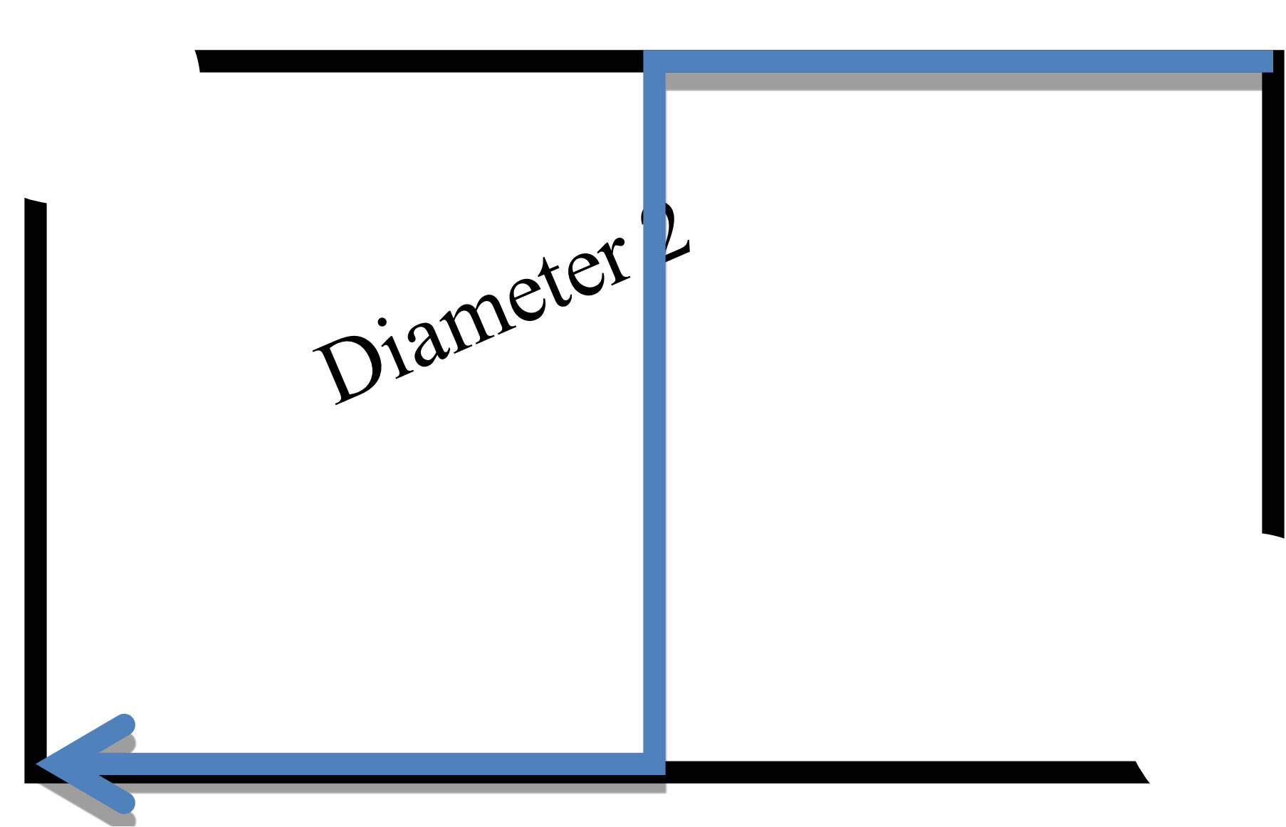
After the determination of the first diameter, a reduction of 40% from the first diameter by removing a circle
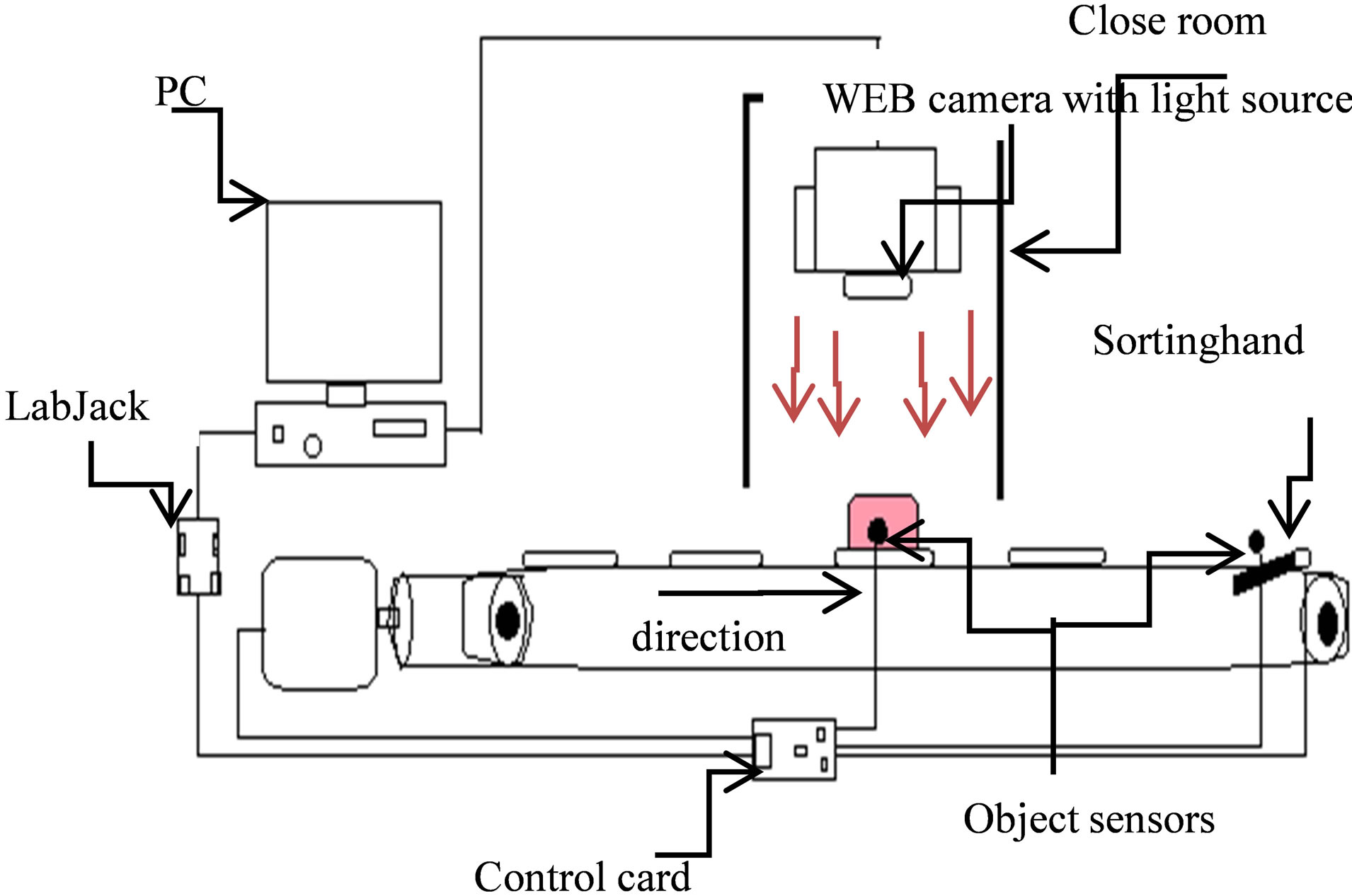
Figure 1. System hardware.
of pixels from both ends of the first diameter as shown in Figure 2. After that the previous procedure are used to calculate the second diameter.
The brick cracks could be detected by tracing the boundaries of the holes inside the brick.
2.2. Brick Recognition
The brick features, (length, width and diameter) must know before brick recognition, the ideal brick dimensions are 24 cm length, 12 cm width and 8 cm height with no crack. The top view of a brick appears as rectangular with X width, 2X length and  X as shown in Figure 3.

Area = 2X × X = 2X2
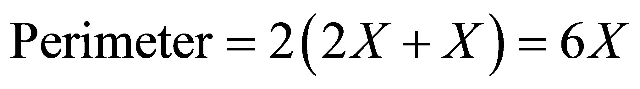
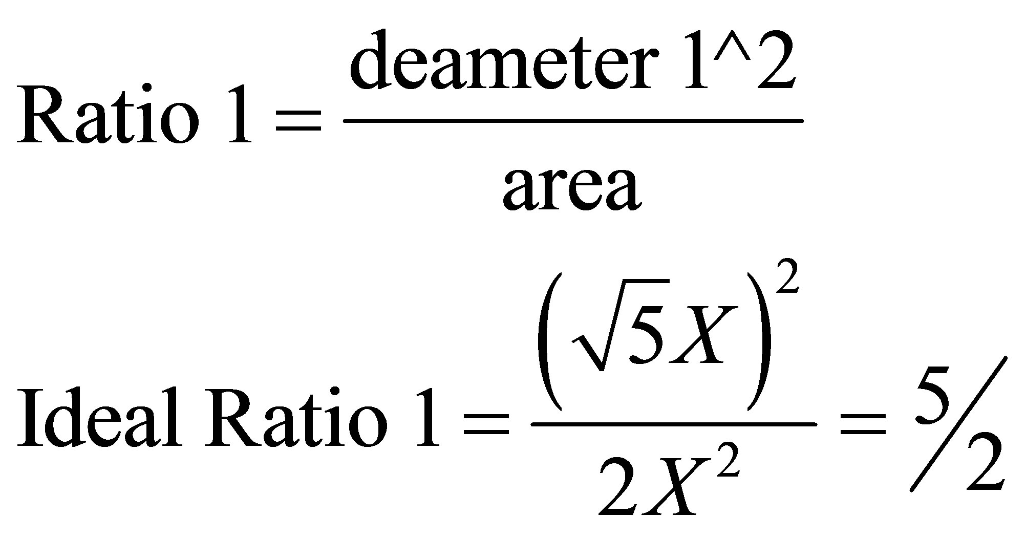
The brick can be recognition by specifying the ratios between (area, perimeter, diameter 1, and diameter 2) as well as the number of cracks.
The equations of ratio is illustrate below:
 (1)
(1)
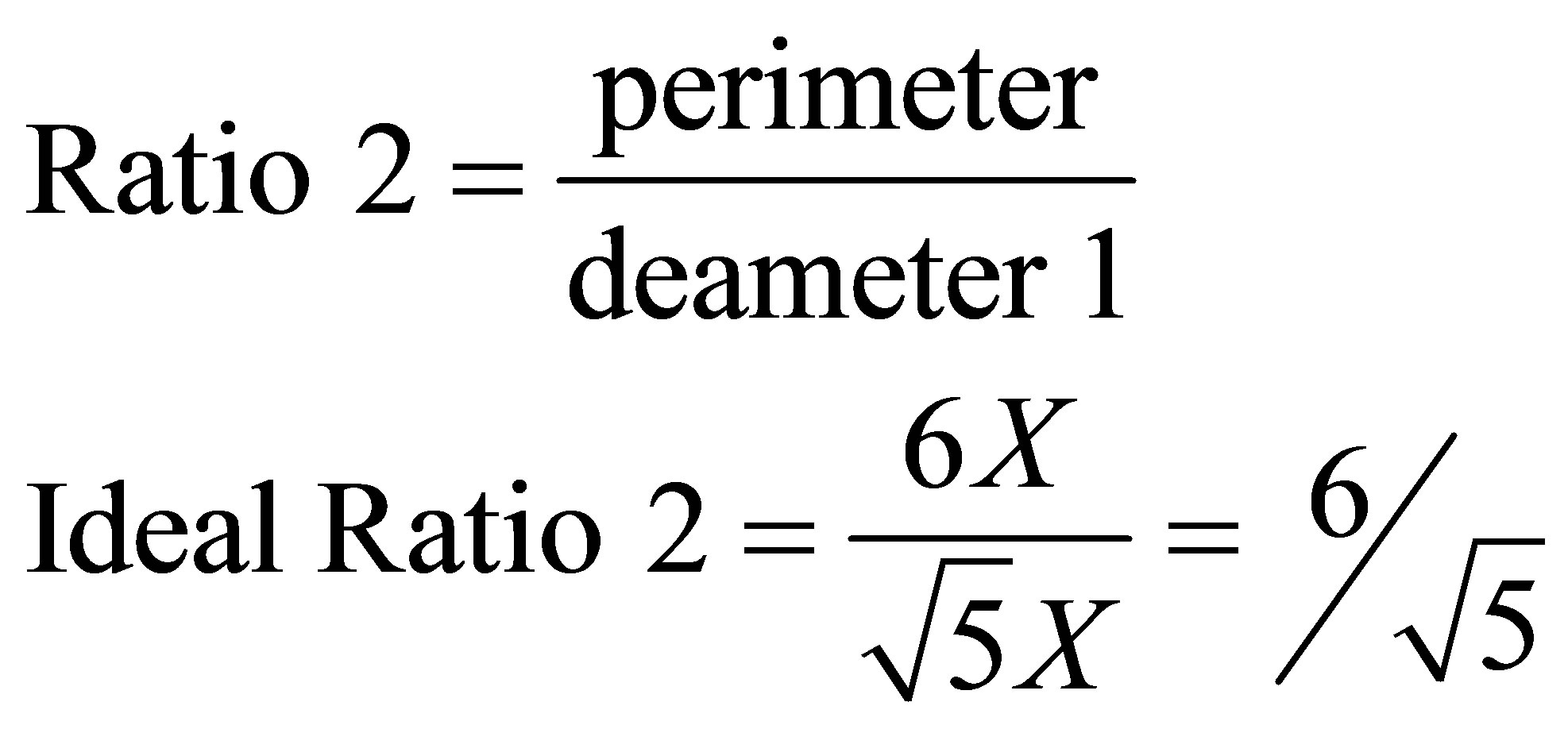 (2)
(2)
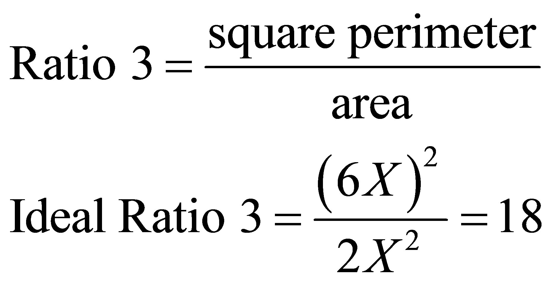 (3)
(3)
 (a)
(a)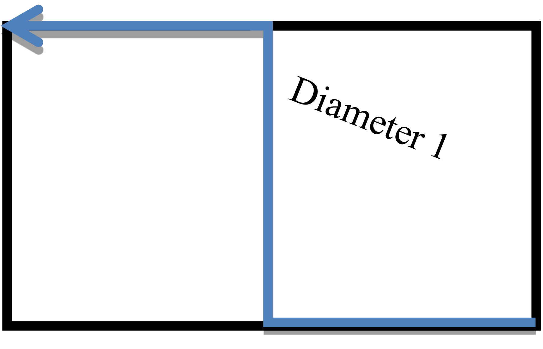 (b)
(b)
Figure 2. Measuring diameter 1 and diameter 2.
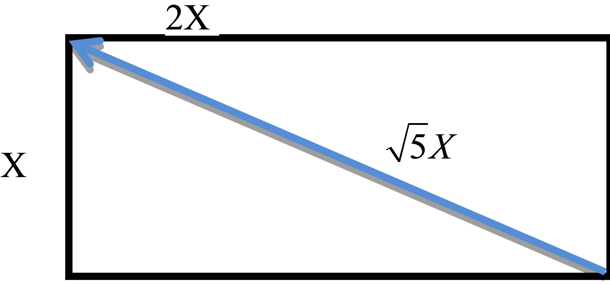
Figure 3. Dimensions of ideal brick.
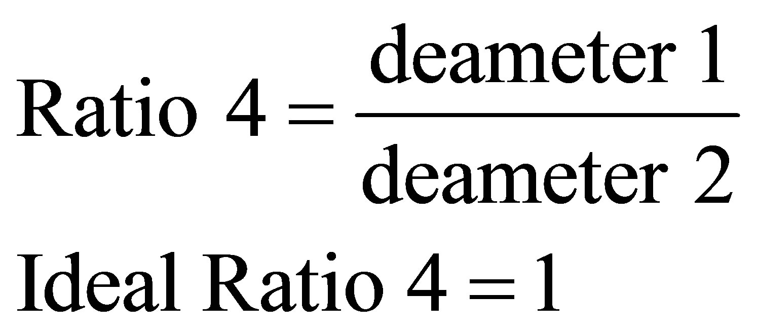 (4)
(4)
Ratio 1, Ratio 2, Ratio 3, Ratio 4 and cracks are the features that are based in recognition of bricks.
3. Quality Measurement
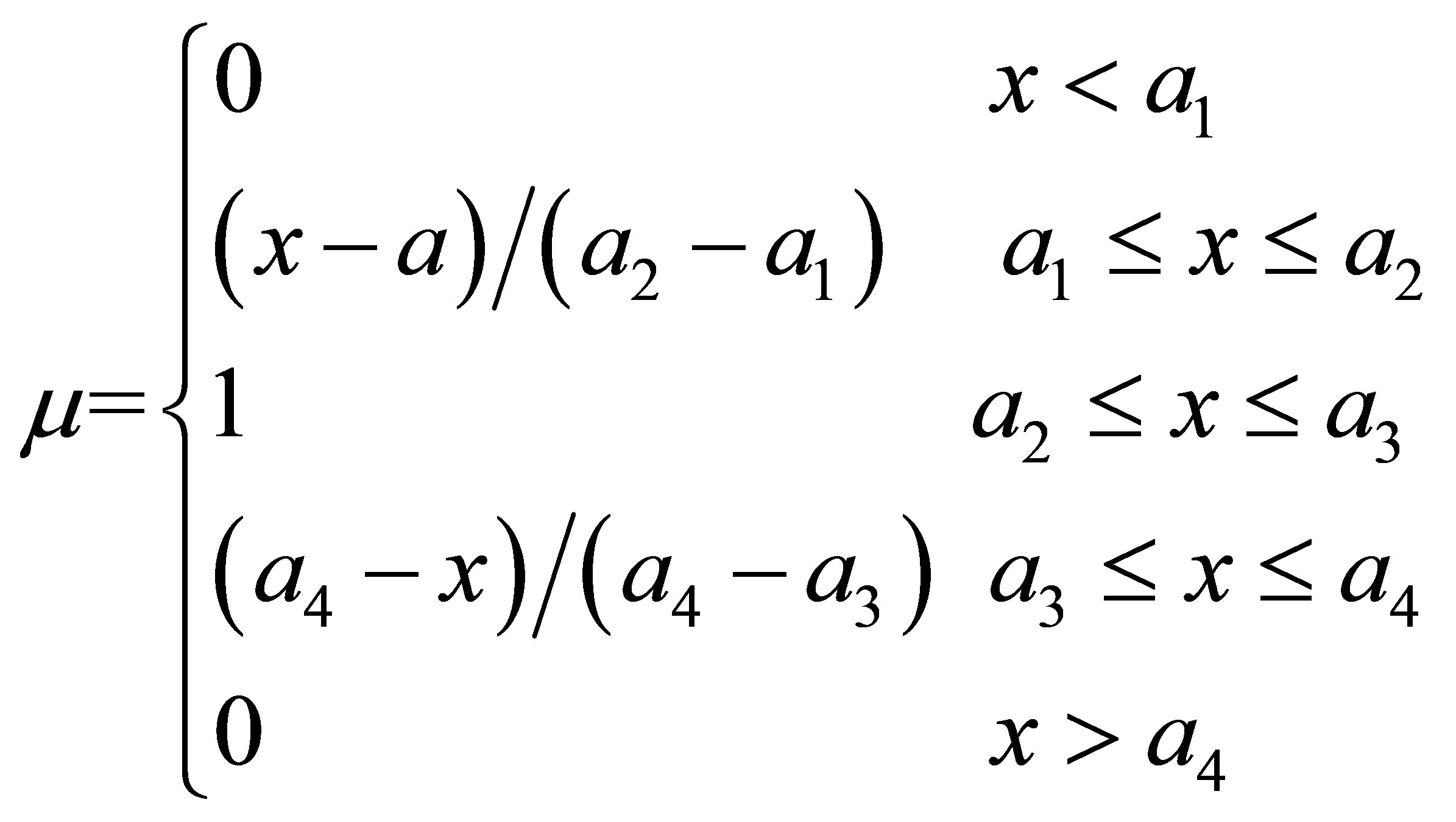
The quality measurements are accomplished using fuzzy system. Ratio 1, Ratio 2, Ratio 3, Ratio 4 and Cracks are used as a fuzzy system input reasoning to determine the brick quality. First of all, the membership of Ratio 1, Ratio 2, Ratio 3, Ratio 4 and cracks must be designed, a trapezoidal function selected to determine the membership of the ratios and the cracks. The trapezoidal function is shown in Figure 4.
The membership for trapezoidal function can be illustrated by the following:
 (5)
(5)
Trapezoidal membership function used directly after inserting the coefficients a1, a2, a3 and a4, so the coefficients of ratios and cracks must be inserted, a suitable values for these coefficients are selected by try and error which are shown in Table 1.
The procedure of quality measurement is drawn from the idea of Van Nauta Lemke [6]; the quality of brick could be calculated as follows:
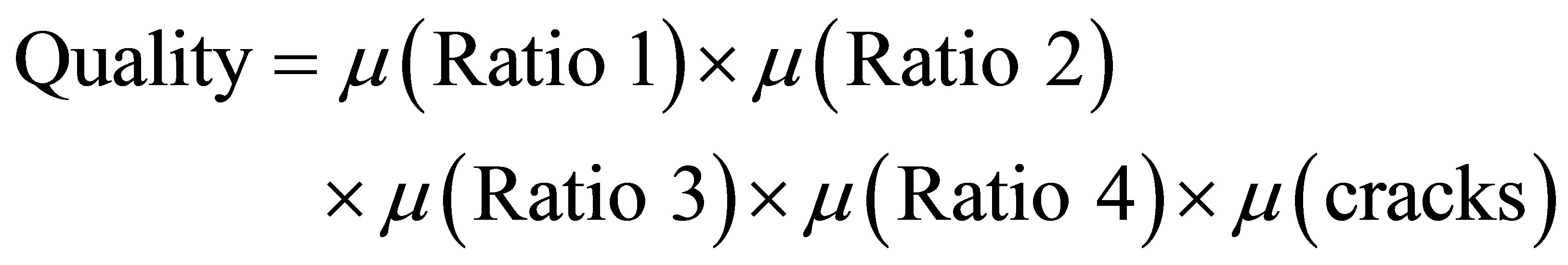 (6)
(6)
Based on the results of Equation (6), the brick either accepted or rejected according to threshold value selected by the user. The sensitivity of quality can easily improved by varying the coefficient values of the memberships function (a1, a2, a3 and a4).
System Flow Chart and Results
An algorithm software has been developed by MATLAB, the system algorithm flow chart for specify brick quality is shown in Figure 5. Four different bricks were taken as samples, Figures 6-9 show these samples, Table 2 shows the brick quality results, the results show that the most affected ratios are Ratio 2 and Ratio 4, and appear that Ratio 3 can remove from quality equations. The membership rations effected significantly on its coefficient and the quality alter depend on the ratios, Table 1 shows the most suitable value coefficient to determine bricks quality.
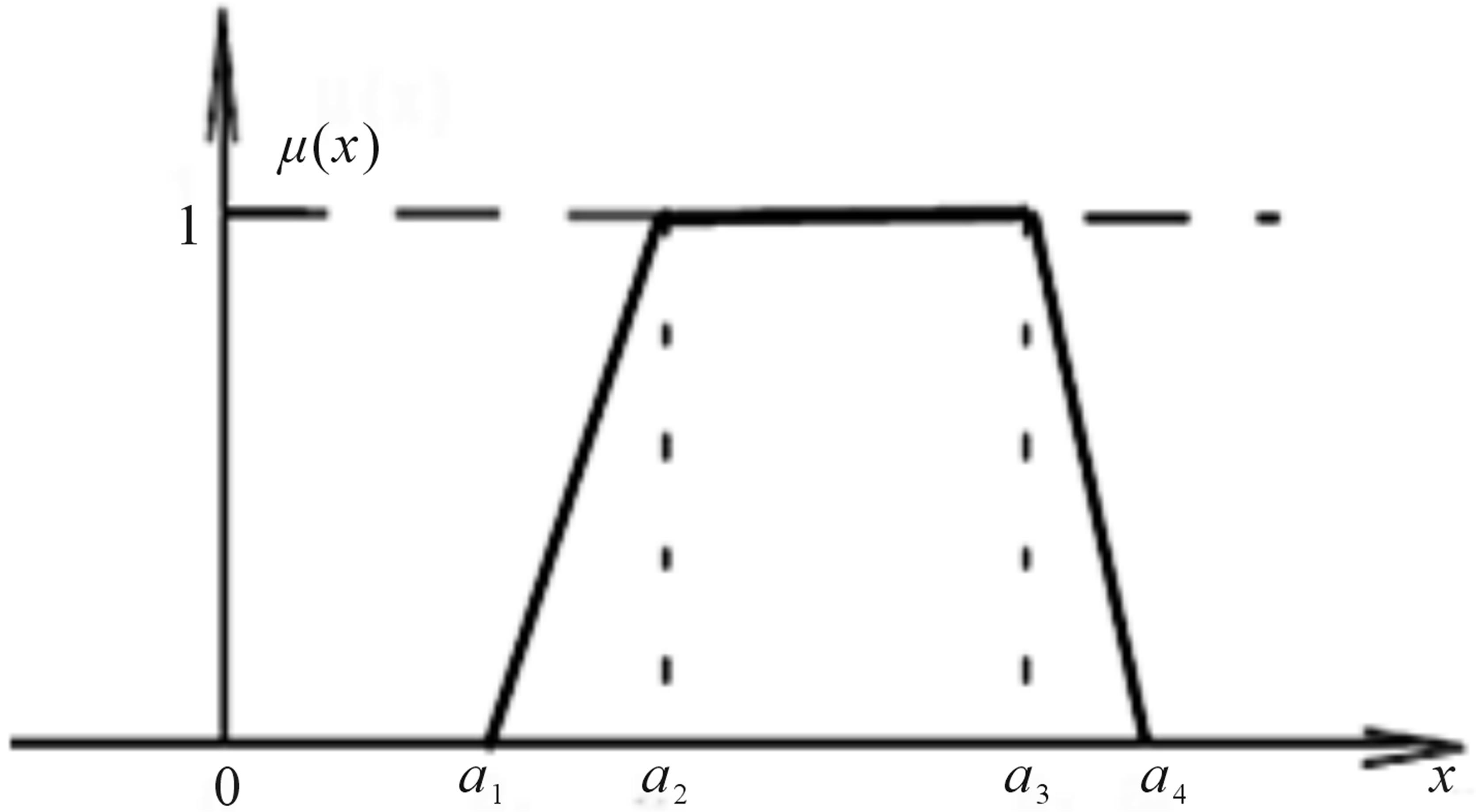
Figure 4. Trapezoidal membership function.
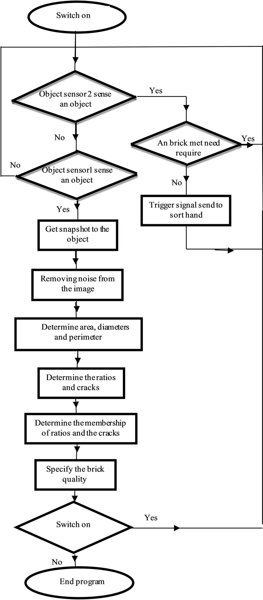
Figure 5. System flow chart.
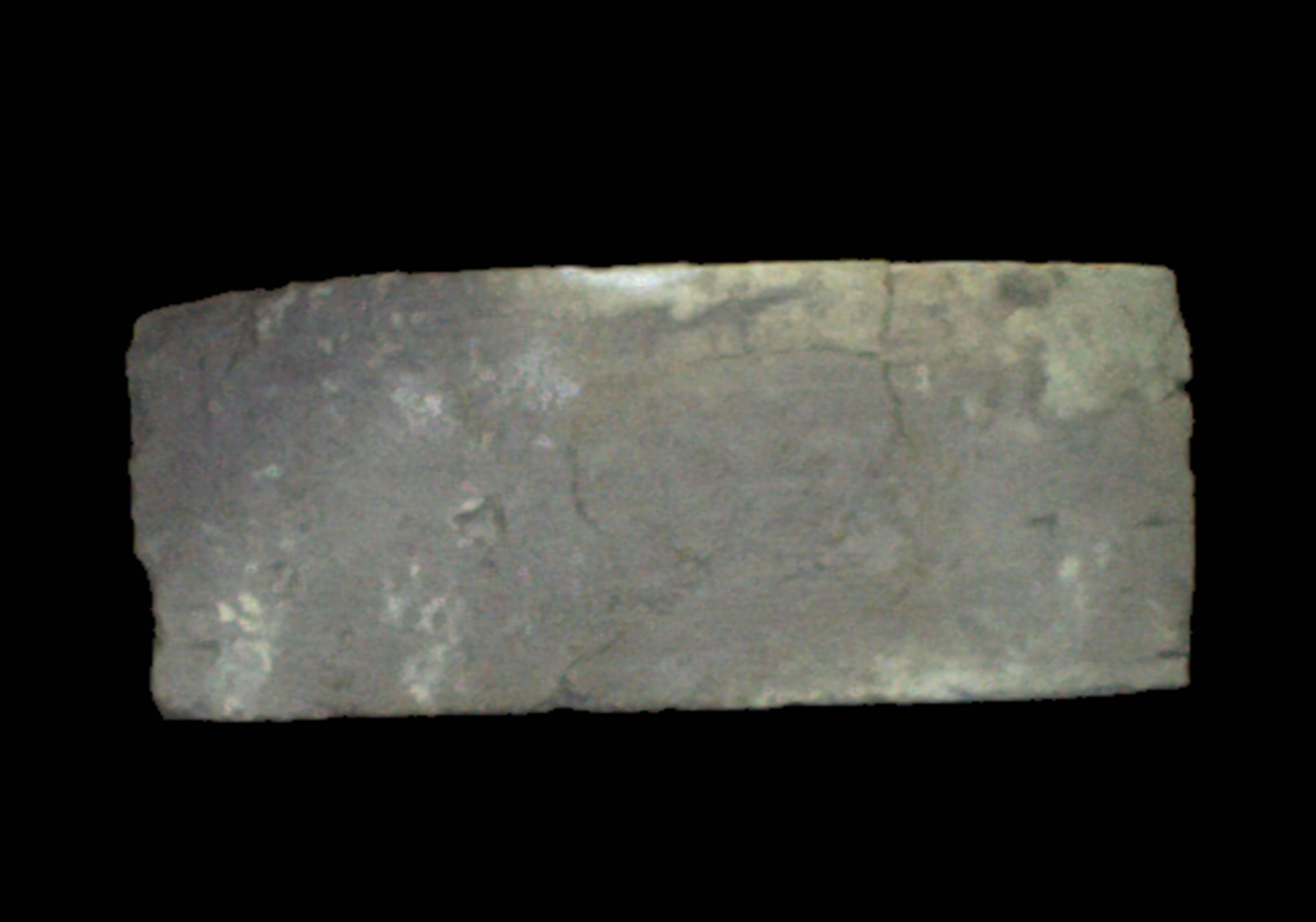
Figure 6. Sample 1.
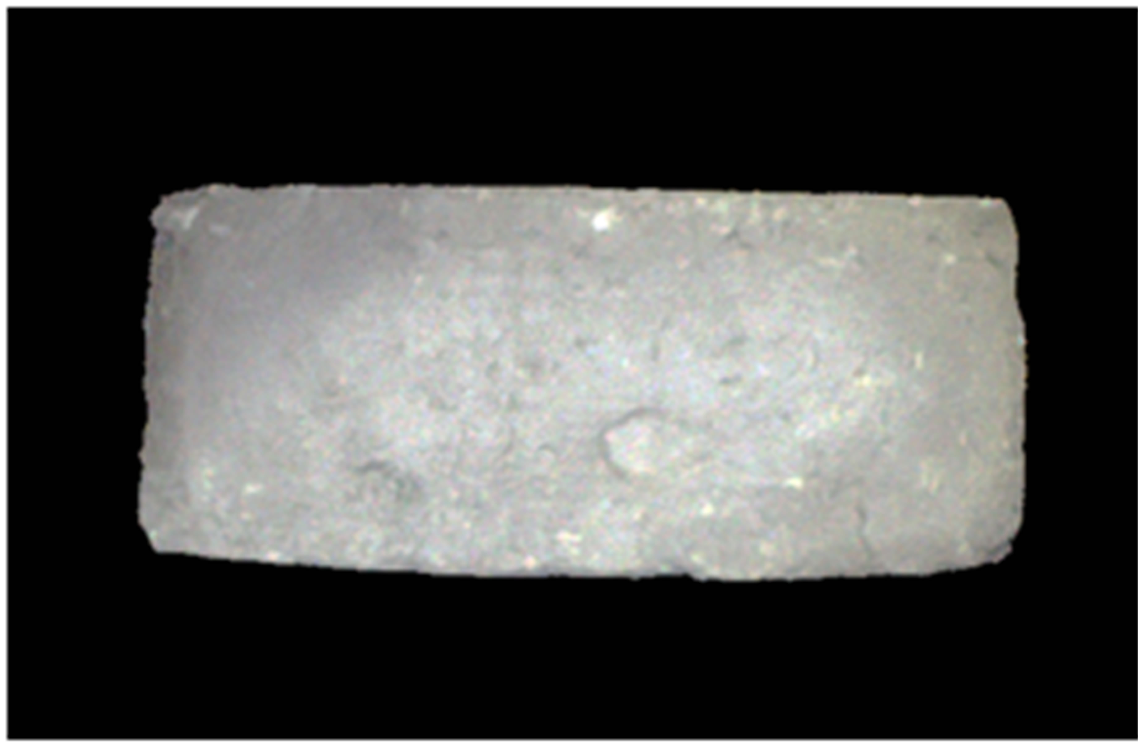
Figure 7. Sample 2.

Figure 8. Sample 3.
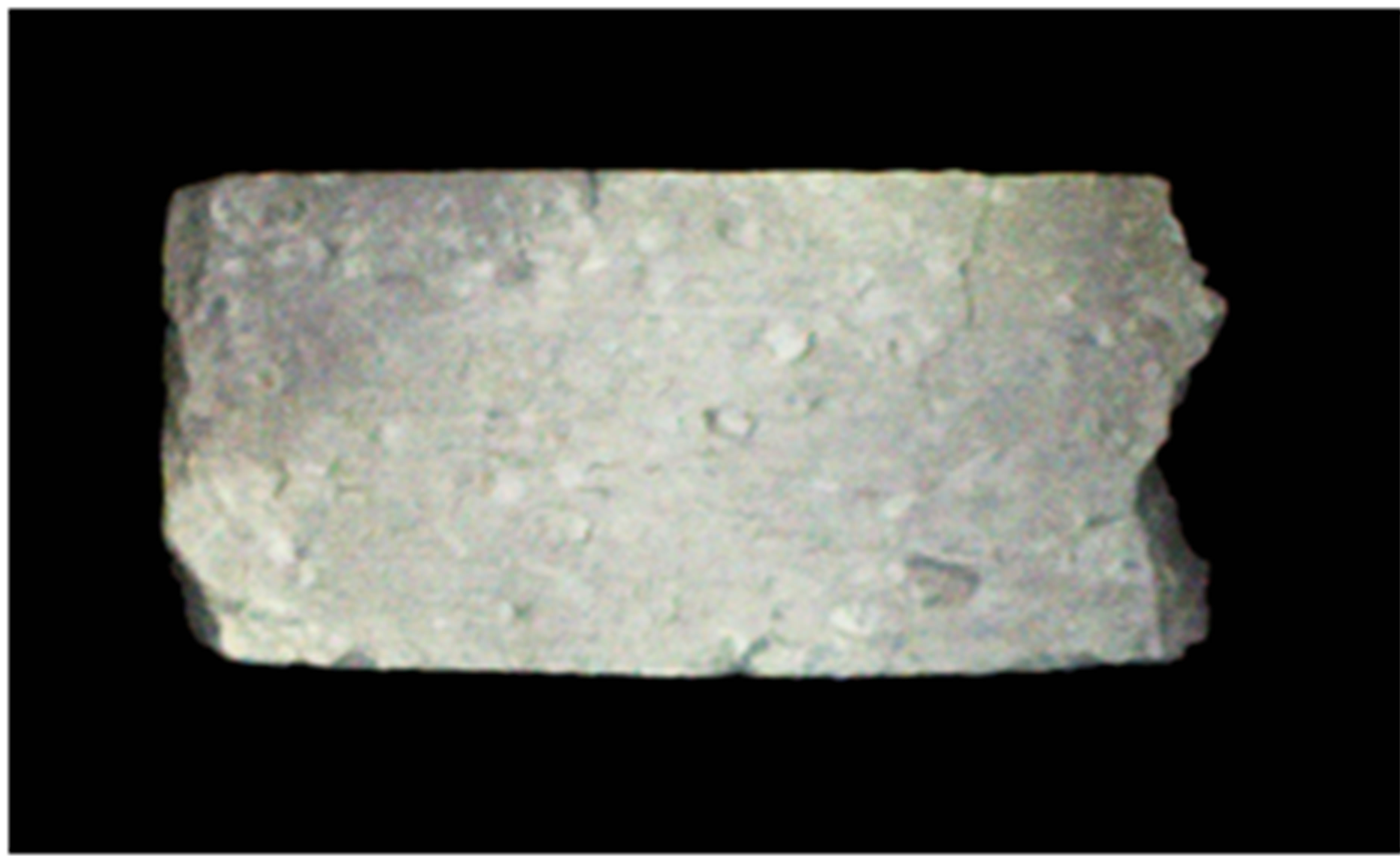
Figure 9. Sample 4.
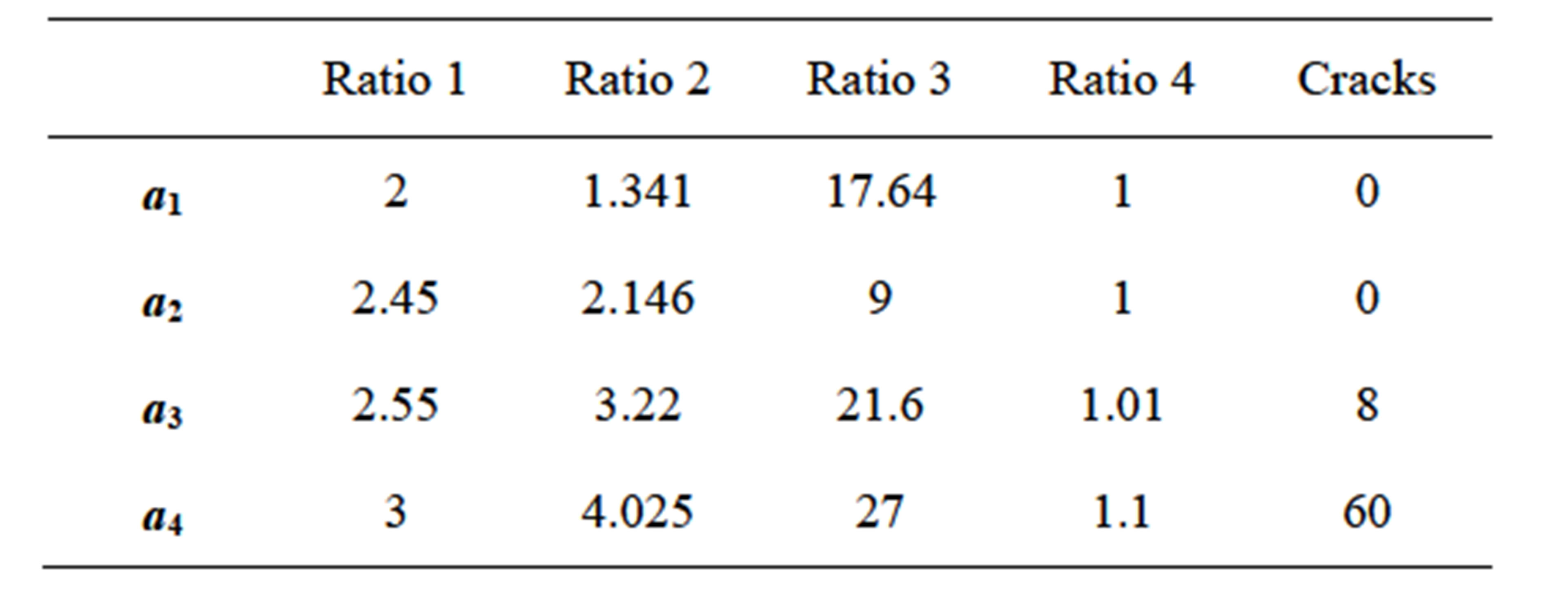
Table 1. The coefficients value.
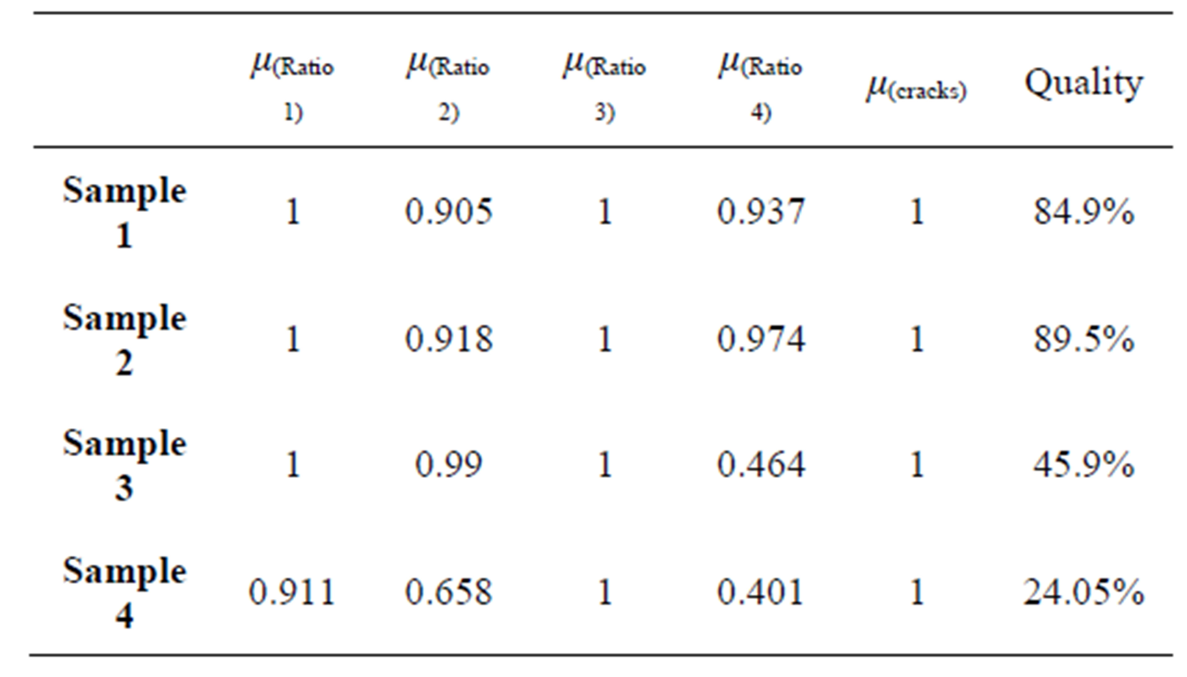
Table 2. Quality results.
4. Conclusion
An automated visual inspection system has been developed to measure bricks quality. The system has the ability to process four bricks per second, and this time is enough to deal with real time manufacture products. The real time inspection method can be expected to improve quality control in manufacturing environment. However, the implementation of computer vision in manufacturing is not simply an image processing problem. The real time visual inspection is an integration system of lighting system, image acquisition, computer, controller and handling equipment. The system solves all these problems and the results show the possibility of using the automated visual system to specify bricks quality.
REFERENCES
- F. You and Y. Zhang, “A Mechanical Part Sorting System Based on Computer Vision,” IEEE International Conference on Computer Science, 2008, pp. 860-863.
- H. Akbar and A. S. Prabuwono, “Webcam Based System for Press Part Industrial Inspection Faculty of Information and Communication Technology,” Technical University of Malaysia Melaka Locked Bag 1200, Hang Tuah Jaya, Ayer Keroh, Melaka.
- J. C. Noordam, G. W. Otten, A. J. M. Timmermans and B. H. van Zwol, “High Speed Potato Grading and Quality Inspection Based on a Color Vision System,” Department Production & Control Systems, ATO, Wageningen.
- J. Blasco, N. Aleixos, S. Cubero, F. Juste, J. Gómez-Sanchis, V. Alegre and E. Moltó, “Computer Vision Developments for the Automatic Inspection of Fresh and Processed Fruits,” Centro de Agroingeniería. Instituto Valenciano de Investigaciones Agrarias (IVIA). Ctra. Moncada-Náquera km 5, 46113 Moncada (Valencia), Spain. Instituto en Bioingeniería y Tecnología Orientada al Ser Humano (Universidad Politécnica de Valencia). Camino de Vera s/n, 46022 Valencia, Electronic Engineering Department, Universidad de Valencia, Dr. Moliner 50, Burjassot, Valencia, Bornimer Agrartechnische Berichte Heft 69, 2011.
- T. Brosnan and D.-W. Sun, “Improving Quality Inspection of Food Products by Computer Vision,” FRCFT Group, Department of Agricultural and Food Engineering, University College Dublin, National University of Ireland, Earlsfort Terrace, Dublin 2, Journal of Food Engineering, Vol. 61, 2004, pp. 3-16. http://dx.doi.org/10.1016/S0260-8774(03)00183-3
- L. Reznik, “Fuzzy Controllers,” Victoria University of Te-chnology, Melbourne, 1997.
NOTES
*Corresponding author.