Journal of Sensor Technology
Vol. 3 No. 2 (2013) , Article ID: 32993 , 5 pages DOI:10.4236/jst.2013.32005
Study of Material Evaluation Probe Using a Longitudinal Wave and a Transverse Wave
1Department of Intelligent Mechanical Engineering, Fukuoka Institute of Technology, Fukuoka, Japan
2Department of Computer Science and Electrical Engineering, Kumamoto University, Kumamoto, Japan
3Mcgill University, Montreal, Canada
Email: *murayama@fit.ac.jp
Copyright © 2013 Riichi Murayama et al. This is an open access article distributed under the Creative Commons Attribution License, which permits unrestricted use, distribution, and reproduction in any medium, provided the original work is properly cited.
Received February 20, 2013; revised March 20, 2013; accepted March 28, 2013
Keywords: Longitudinal wave; Transverse wave; Material property evaluation; High temperature measurement
ABSTRACT
Transmitting a longitudinal wave and a traverse wave into a composite material in a molten state has been studied in the online control of the composite material which cannot be evaluated by a conventional ultrasonic sensor as a final analysis, using the difference in the propagation characteristics of both modes. It is especially expected that measurement of the physical quantity which was not able to be conventionally measured can be performed by carrying out coincidence measurement of the ultrasonic wave in both modes. Therefore, in this research study, an ultrasonic probe, which can simultaneously transmit and receive a longitudinal wave and a traverse wave has been developed using an electromagnetic acoustic transducer (EMAT) because it has the advantage of measuring high temperature samples. In this study, two methods have been compared. The 1st method uses a traverse wave EMAT that travels in a vertical direction and a bar wave by which the low order mode is equivalent to longitudinal wave vibration. The other method is to carry out the mode conversion of the traverse wave by a traverse wave-EMAT. The longitudinal converted from the transverse wave are spread in the axis direction. As the experimental results of both optimizations of the drive conditions, it has been confirmed that the 2nd mode conversion method was promising. This paper reports about the trial process and the experimental results.
1. Introduction
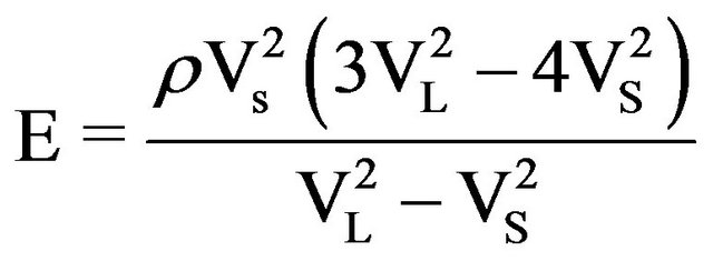
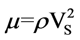
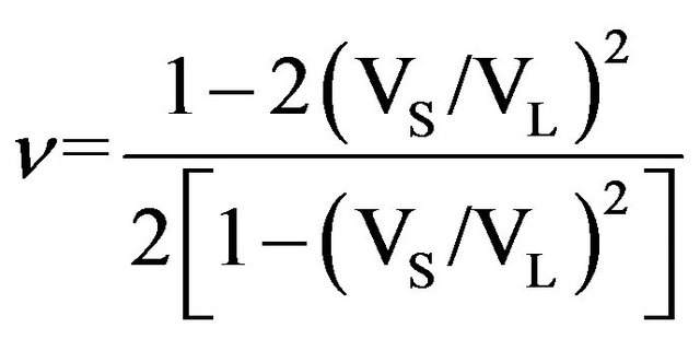
For the NDT and SHM in the composite material industry, it is crucial to know the elastic properties such as Young’s modulus, shear modulus, Poisson’s ratio anisotropy, texture or stress. Ultrasonic techniques are often used to evaluate or nondestructively characterize such properties. Since many parts or structures are subject to high temperature, it is of interest and sometimes even mandatory to characterize their properties at high temperature [1-3]. Thus ultrasonic testing at high temperature has become important. The Young’s modulus E, shear modulus μ and Poisson’s ratio v of an isotropic material can be obtained knowing the longitudinal wave velocity VL and transverse wave velocity VS. Their relations are given in Equations (1)-(3), respectively.
 (1)
(1)
 (2)
(2)
 (3)
(3)
Where E, Young’s modulus, is the ratio of the applied longitudinal stress to the longitudinal strain when a rod is subjected to a uniform stress over its end planes and its lateral surface is free to expand. Where μ, the shear modulus, is the ratio of the transverse stress to transverse strain. Where v, Poisson’s ratio, is the ratio of the lateral contraction (expansion) to the longitudinal extension (contraction) of the rod.
2. Concept of Trial Ultrasonic Probes Using a Bar Wave and a Transverse Wave
Figure 1 shows the generating principle of a bar-wave. If a biased magnetic field by a magnet and high frequency induced magnetic field by an electromagnetic-induced
 (a) (b)
Figure 1. robe using bar wave. (a): Drive principle; (b): Outline the Probe.
coil is produced in the long direction of the shaft part of a trial probe, an induce vibration by a Magnetostrictive effect on the surface is introduced. It will be converted into a bar wave, which is a kind of ultrasonic wave, if the diameter is enough small. The vibration of this bar wave serves as a compressional wave and converts into a longitudinal wave at the step part of the trial ultrasonic probe, and it crosses the probe [4]. An EMAT for the traverse wave was installed on the top surface of the trial ultrasonic probe and injects a transverse wave into the probe. It crosses the probe.
Finally, the simultaneous transmission and reception of the longitudinal wave and transverse wave is performed by combining the two kinds of generating procedures.
Figure 2 shows the generating principle of a transverse wave which crosses a specimen in the thickness direction by an electromagnetic acoustic wave transducer (EMAT). An EMAT consists of a magnet and an electromagnetic induction coil. It generates a magnetic field and high frequency electric current on the surface of the specimen. It then generates a Lorentz force in the horizontal direction on the surface which changes the direction according to the high frequency electric current in the induction coil. It converts to a transverse wave which crosses the specimen in the thickness direction [5,6].
3. Concept of Trial Ultrasonic Probes Using Ultrasonic Mode Conversion
Figure 3(a) shows the principle of the ultrasonic mode conversion according to Snell’s law. During the mode conversion process, a traverse wave converts into a longitudinal wave according to Snell’s law using equation (4). Figure 3(b) shows an outline of an ultrasonic wave using this mode conversion method [7-9]. When the sensor coil for traverse waves is installed on the side of the probe, the traverse is reflected on the opposite inclined wall and converted into a longitudinal wave on the slope. This longitudinal wave crosses in the vertical direction. When a transverse wave-EMAT was installed on the top surface of the probe, the EMAT injected a longitudinal wave into the probe. This longitudinal wave crosses the
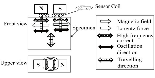
Figure 2. principle of the transverse EMAT.
 (a) (b)
Figure 3. Trial ultrasonic probe using mode transformation method. (a): Drive principle; (b): Outline the Probe.
probe and arrives at the bottom surface. Finally these two types of transmission and reception method are performed simultaneously. If we then assume the trial probe as shown in Figure 3(b), θ1 as 28.71˚, as 61.29˚ by using equation (1) if θ1 + θ2 was supposed to be 90˚. Finally, these two types of transmission and reception methods are simultaneously performed.
 (4)
(4)
θ1: Injection and feflection angle at the same mode.
θ2: Reflection angle in the different modes.
V1: Longitudinal wave velocity (m/s).
V2: Transverse wave velocity (m/s).
4. Experimental Results of a Transverse Wave-EMAT
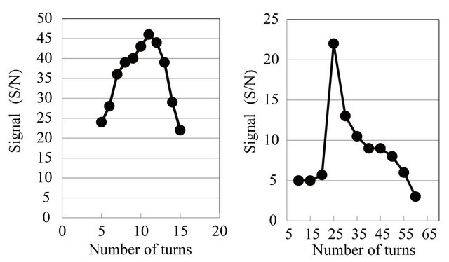
The traverse wave-EMAT was optimized because the EMAT was used by both types of ultrasonic waves, as a transverse wave sensor in the case of a bar and a transverse wave-probe, as the original ultrasonic source sensor in the case of the mode conversion probe. The pillar type neodymium magnet with 30 mm diameter was used to apply a biased magnetic field. The circular type electromagnetic induction coil was used. Figure 4(a) shows the relationship between the number of turns of the transmitter coil and the received signal intensity. Figure 4(b) shows the relationship between the number of turns
 (a) (b)
Figure 4. Relationship between the signal amplitude and the number of turns. (a):Transmitter; (b): Receiver.
of the transmitter coil and the received signal intensity. As a result, the transmitter coil with 11 turns and the receiver coil 25 turns were selected. In addition, a 2 MHz drive frequency and 10-mm diameter of the coil was selected. Figure 5 shows the received signal waveform using the best condition with a test block of 70-mm thickness. The reflected signal at the bottom surface was detected with a good S/N.
5. Ultrasonic Probe Using Bar Wave
The transverse wave-EMAT was used as a transverse wave source and the bar wave EMAT, which consists of a cylindrical-shaped magnet with 1000 number of turns, and a cylindrical-shaped electromagnetic induction coil with 10 number of turns wound around the step part were used as a longitudinal wave source. The trial probes with 10 mm, 12 mm, 14 mm, 18 mm, 22 mm, 26 mm diameters at the step part were fabricated. The height and the maximum diameter of the trial probe were 140 mm and 30 mm. Figure 6 shows the experimental results. As the shaft part diameter increased, the detected transverse wave signal was improved, but the longitudinal wave signal became poor. As a conclusion, this trial method was not fit for simultaneously transmitting and receiving a transverse wave and a longitudinal wave.
6. Ultrasonic Probes Using Ultrasonic Mode Conversion
The probe for the mode conversion with a 58-mm height and 40 mm length is shown in Photo 1. The electromagnetic induction coils with the same specification were installed on the top surface of the probe and on the other side surface at an slope of 28.7˚. The schematic diagram is shown in the Figure 7. The pulsar was used to drive the electromagnetic induction coil. The amplifier was used to amplify the signal by 40 dB. An Nd permanent magnet was used to apply the static magnetic field on the surface of the probe. Figure 8 shows the received signal
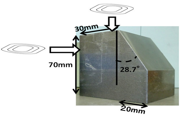
Photo 1. Overlook of the trial probe.
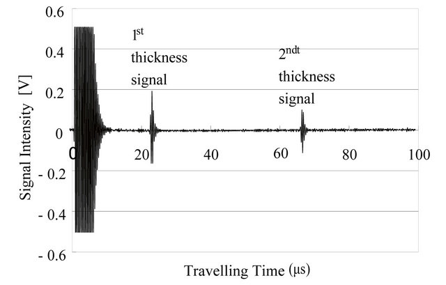
Figure 5. Received signal waveform.
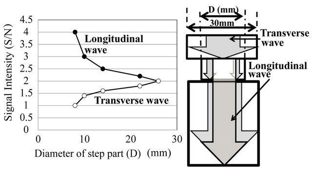
Figure 6. Shaft part-diameter and signal amplitude.
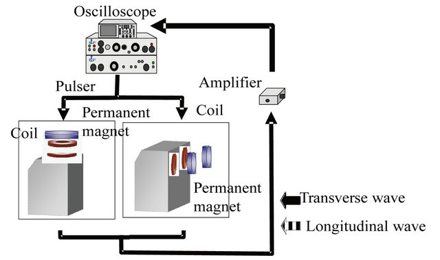
Figure 7. Schematic diagram.
 (a) (b)
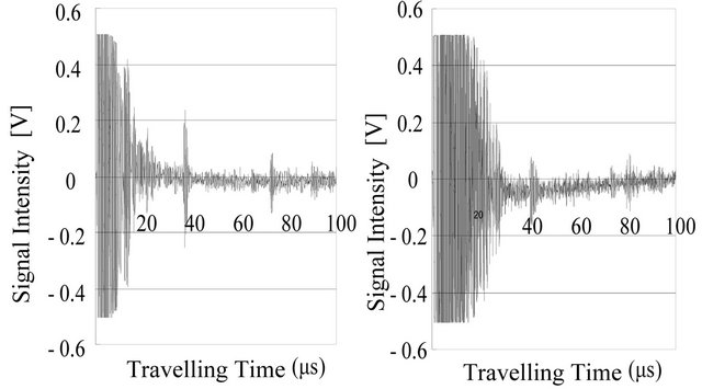
Figure 8. Detected signal waveform. (a): Longitudinal wave; (b): Transverse wave.
waveform. Both the transverse wave and the longitudinal wave signal with a good S/N, which were reflected by the bottom surface of the probe, were detected as shown in Figure 8.
7. High Temperature Experiment
The trial probe simultaneously driving longitudinal wave and traverse wave was heated from 20˚C to 180˚C in 20˚C steps. Figure 9 shows the relationship between the temperature of the probe and both velocities. Figure 10 shows the relation between the temperature of the probe and the signal intensity. While the probe was heating, the longitudinal wave velocity changed from 5865 [m/s] to 5783 [m/s], and the traverse wave velocity changed from 3115 [m/s] to 3017 [m/s]. This means that the change ratio was 1.3% in the longitudinal wave and 3.1% in the transverse wave. As for the signal intensity, the longitudinal wave intensity dramatically decreased as the temperature increased, but the transverse wave intensity did not significantly change.
8. Conclusions
An ultrasonic probe, which can simultaneously transmit and receive the traverse wave and the longitudinal wave by the EMAT, was developed. The ultrasonic probe using the bar wave could not detect the received signal with a good S/N. Although a small diameter at the step part of the ultrasonic probe was needed to generate the bar wave with good intensity, it meant that the transvers wave coming through from the upper side of the shaft part was blocked at the shaft part. That is why the development of this type of ultrasonic probe was stopped.
The ultrasonic probe using the mode conversion method could detect the transverse wave and the longitudinal wave. However, the longitudinal wave intensity was smaller than the transverse wave.
It is necessary to improve this method such that improvement in the conversion rate at the time of changing into a longitudinal wave from a traverse wave from now
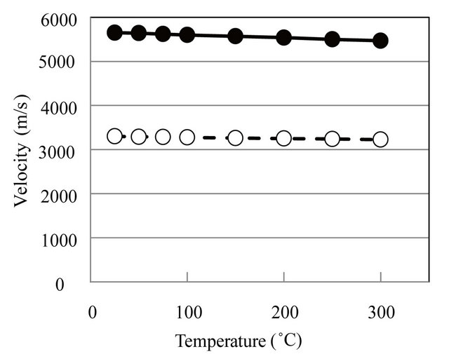
Figure 9. Temperature and the velocity.

Figure 10. Temperature and the signal intensity.
on and the high temperature of 200˚C or more can also be borne.
REFERENCES
- L. Beloqui, J. Krautkrämer and H. H. Krautkrämer, “Ultrasonic Testing of Materials,” 4th Edition, Springer, Berlin, 1990, pp. 528-550.
- B. A. Auld, “Acoustic Fields and Waves in Solids,” New York, Vol. 2, 1973, pp. 30-38.
- R. Kazys, A. Voleisis, R. Sliteris, L. Mazeika, R. V. Nieuwenhove, P. Kupschus and H. A. Abderrahim, “High Temperature Ultrasonic Transducers for Imaging and Measurements in a Liquid Pb/Bi Eutectic Alloy,” IEEE Transactions on Ultrasonics, Ferroelectrics and Frequency Control, Vol. 52, No. 4, 2005, pp. 525-537. doi:10.1109/TUFFC.2005.1428033
- T. Arakawa, K. Yoshikawa, S. Chiba, K. Muto and Y. Atsuta, “Applications of Brazed-Type Ultrasonic Probes for High and Low Temperature Uses 2,” Nondestructive Testing and Evaluation, Vol. 7, No. 1-6, 1992, pp. 263-272. doi:10.1080/10589759208953005
- R. B. Thompson, “A Model for the Eletromagnetic Generation and Detection of Rayleigh and Lamb Wave,” IEEE Transaction on Sonics and Ultrasonics, Vol. 20, No. 4, 1973, pp. 340-346. doi:10.1109/T-SU.1973.29770
- M. Hirao and H. Ogi, “EMATS for Science and Industry,” Kluwer Academic Publishers, 2003. doi:10.1007/978-1-4757-3743-1
- Y. Ono, C.-K. Jen and M. Kobayashi, “High Temperature Integrated Ultrasonic Shear and Longitudinal Wave Probes,” Review of Scientific Instruments, Vol. 78, No. 2, 2007, pp. 1-5. doi:10.1063/1.2669719
- C.-K. Jen, Y. Ono and M. Kobayashi, “High Temperature Integrated Ultrasonic Shear Wave Probes,” Applied Physics Letters, Vol. 89, No. 18, 2006, pp. 1-4. doi:10.1063/1.2372767
- M. O. Si-Chaib, H. Djelouah and M. Bocquet, “Applications of Ultrasonic Reflection Ode Conversion Transducers in NDE,” NDT & E International, Vol. 33, No. 2, 2000, pp. 91-99. doi:10.1016/S0963-8695(99)00027-4
NOTES
*Corresponding author.