Journal of Sensor Technology
Vol.2 No.2(2012), Article ID:19675,8 pages DOI:10.4236/jst.2012.22009
Noncontact Driving System Using Induction-Based Method and Integrated Piezoelectric Ultrasonic Transducers
1Fukuoka Institute of Technology, Fukuoka, Japan
2Kumamoto University, Kumamoto, Japan
3National Research Counsil of Canada, Ottawa, Canada
4Mcgill University, Montreal, Canada
Email: *murayama@fit.ac.jp
Received April 26, 2012; revised May 20, 2012; accepted May 28, 2012
Keywords: Ultrasonic Wave; Noncontact Sensing; Integrated Ultrasonic Transducer; Electromagnetic Induction Law
ABSTRACT
Integrated Ultrasonic Transducers (IUTs) have been developed for high-temperature nondestructive evaluation applications. In many field, it would be helpful if a pipe covered by a protective layer of about 10 cm thickness, which is under operation at several hundred Celsius, could be inspected from above the protective layer by an IUT. As a first step toward achieving the inspection of such a pipeline, an induction-based method using coils is presented together with IUTs. This study focuses on the effects of the separation distance (liftoff) between the coils on the ultrasonic signal strength and bandwidth of the IUTs. Ultrasonic signals were generated and received by the IUTs on a steel plate with a sufficient strength for thickness measurements when the liftoff was 20 cm. It was also shown that a ferrite disc together with the coils enhanced the received signal strength even when the liftoff was over 10 cm.
1. Introduction
Ultrasonic methods employing piezoelectric Ultrasonic Transducers (UTs) are widely used for the real-time, in situ, or off-line nondestructive evaluation (NDE) of large metallic and polymeric composite structures including airplanes, automobiles, ships, pressure vessels, and pipelines. Their merits are subsurface and inner inspection capability, high inspection speed, simplicity, and costeffectiveness [1,2]. Common limitations of current UTs are the requirement of a couplant and their difficulty of use at High Temperatures (HTs) and with curved surfaces. However, in the in-line monitoring of industrial processes and NDE of the structures mentioned above, UTs are often required to operate at HTs [3-8]. To meet these requirements, integrated ultrasonic transducers (IUTs) have been developed for HT NDE applications [9-12]. In particular, the pipeline near the reactor of a nuclear plant which operates at several hundred Celsius is often covered with a protective layer of about 10 cm thickness. It would be very useful in ensuring the safe operation of nuclear plants if NDE could be performed from above the protection layer without peeling off the protection layer. Next, it would require many IUTs to be placed on the structure and connections between IUTs and drive instruments using many cables to inspect large areas of HT structures. These cables might not be able to endure a high temperature for a long time. In addition, connecting the IUTs may be laborious. If a technique can be developed to drive IUTs on a material at a distance exceeding 10 cm, it would make it possible to inspect pipelines automatically.
Here an induction-based evaluation method [13,14] using coils is presented together with IUTs using PZT powders that can operate at temperature of up to 200˚C as a first step. This investigation focuses on the effects of the separation (liftoff) distance between the coils and the coil diameter on the ultrasonic signal strength and bandwidth of the IUTs.
2. Ultrasonic Transducers
A steel plate with a thickness of 12.7 mm was used as the substrate for the IUTs as shown in Figure 1 [11,12]. A Lead-Zirconate-Titanate (PZT) composite (PZT-c) slurry consisting of PZT powder with a submicron average particle size and a PZT sol-gel was directly sprayed onto the steel plate. After spraying each PZT-c slurry coating, thermal treatment was carried out to form a solid PZT-c film. Multiple layers were formed until the desired film thickness was reached, leading to IUTs with suitable ultrasonic operating frequencies. Then, electrical poling was used to induce the piezoelectricity of the thick PZT-c (>60 mm) film. Finally, a top electrode pattern, which defined the active element size of the IUT was painted using silver paste. In this study, PZT-IUT that could operate up to about 200˚C and had a center frequency of ~10 MHz, which was frequency allowing the easiest fabrication, was prepared. As a next step, another type of IUT that can operate up to about 600˚C and has a center frequency of ~5 MHz, the frequency usually used in NDE, will be fabricated.
In this study, an induction-based evaluation method [13,14] was used. First, flat circular coils made of thin copper wires with lacquer coatings served as the main component for induction coupling. The two ends of one coil, denoted as Coil-1, were connected to the top electrode of the IUT and the steel substrate serving as the bottom electrode of the IUT. Another coil, denoted as Coil-2, was connected to the pulser/receiver. A schematic diagram of this inductive noncontact ultrasonic measurement configuration is given in Figure 2. Electromagnetic (EM) waves generated by Coil-2 induce electric current into Coil-1, which activate the IUT. The activated IUT generates and receives longitudinal ultrasonic waves that traverse back and forth within the thickness of the steel plate. The IUT also induces an electric current and activates Coil-1. Coil-2 is then activated by the EM waves generated by Coil-1 and generates an electric current as a signal that is fed to the receiver. The received ultrasonic signal could only detected up to a liftoff of about 0.5 cm when this technique was applied [13,14]. The study then focused on improving the ultrasonic signal strength and the liftoff characteristic, so that NDE could be performed even if the liftoff was over 10 cm.
When EM coils are applied to excite and receive ultrasonic signals in IUTs, the transduction efficiency of the sensor depends on the magnitude of the mutual induction coefficient (k) between Coil-1 and Coil-2 and
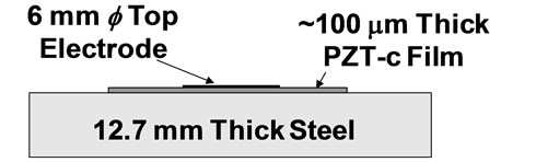
Figure 1. Basic test sample with an IUT.
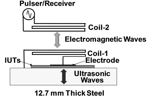
Figure 2. Principle of noncontact induction-based ultrasonic sensor using IUT.
electrical impedance-matching between Coil-2 (ZC2) and the receiver (Zr), between Coil-2 and the pulser (Zp), and between Coil-1 (ZC1) and the IUT (ZIUT).
First, the two coils were fabricated with flat circular shapes to obtain the value of mutual induction coefficient (k). Next, coils with various numbers of turns were fabricated to determine the optimal number of turns for each coil. For example, the electric power generated by Coil-2 can be expressed by Equation (1). This equation implies that there is optimal impedance that can generate the maximum electric power given by Equation (2).
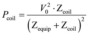 (1)
(1)
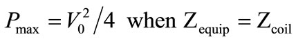 (2)
(2)
Pcoil: Electric power generated by coil;
V0: Output voltage of pulser;
Zcoil: Electric impedance of coil;
Zequip: Output impedance of an equipment;
Pmax: Maximum electric power generated by coil.
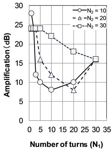
When considering the use of two coils as a transformer, the electric power in Coil-1, when connected to an IUT, generated by a pulser is proportional to the ratio of the number, N, of turns of the two coils, as shown by Equation (3). However, after the electric power generated in Coil-1 by an IUT, the electric power generated in Coil-2 is proportional to the reciprocal number of that in Coil-1 as shown in Equation (4). It can thus be expected that the optimal numbers of turns in Coil-1 and Coil-2 are the same.
 (3)
(3)
 (4)
(4)
ΔE1: Electric power generated in Coil-1;
ΔE2: Electric power generated in Coil-2;
N1: Number of turns of Coil-1;
N2: Number of turns of Coil-2.
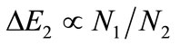
Next, according to the Biot-Savart law, the magnetic field intensity on the center axis with the distance d from the center point of a coil generated by a circular coil is given by Equation (5). The magnetic field computed using Equation (5) is shown in Figure 3. When the liftoff distance is increased by 20 cm, the magnetic field induced by a coil with inner diameter, D, of 0 cm decreases by about 100 dB, but the magnetic field induced by a coil with D = 20 cm decreases by only 35 dB. Therefore, coils with different D were fabricated to determine the liftoff characteristics.
 (5)
(5)
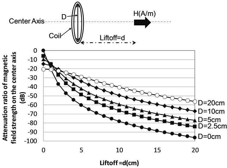
Figure 3. Magnetic field strength on the center axis of a circular coil due to liftoff.
H: magnetic field on the center axis at distance d from the center point of a coil;
D: diameter of coil;
I: electrical current;
N: Number of turn of a coil;
d: Distance on the center axis from the center point of a coil.
The specifications of the fabricated circular coils are given in Table 1. The coils are classified into two groups. Coils in the first group (left column) were used to evaluate the effect of N while D was fixed at 1.5 cm. Those in the second group (right column) were used to determine the relation between D and the liftoff characteristic, d, between the Coil-1 and Coil-2. In experiments, both Coil-1 and Coil-2 have the same D and N. In Table 1, d is the liftoff distance between the two coils, and N was set so that each coil had nearly the same Zequip as the coil with D = 1.5 cm, which showed high ultrasonic sensitiveity.
3. Experimental Results
3.1. Optimal Number of Turns
First the optimal value of N was evaluated for coils with D = 1.5 cm at room temperature. Figures 4(a) and (b) show the signal amplitude dependence on N1 and N2. The results demonstrate that there are optimal N’s for Coil-1 and Coil-2. The relationship between the optimal values of N1 and N2 is presented in Figure 4(c). It was observed that the strongest signal was obtained when N1 and N2 were almost the same.
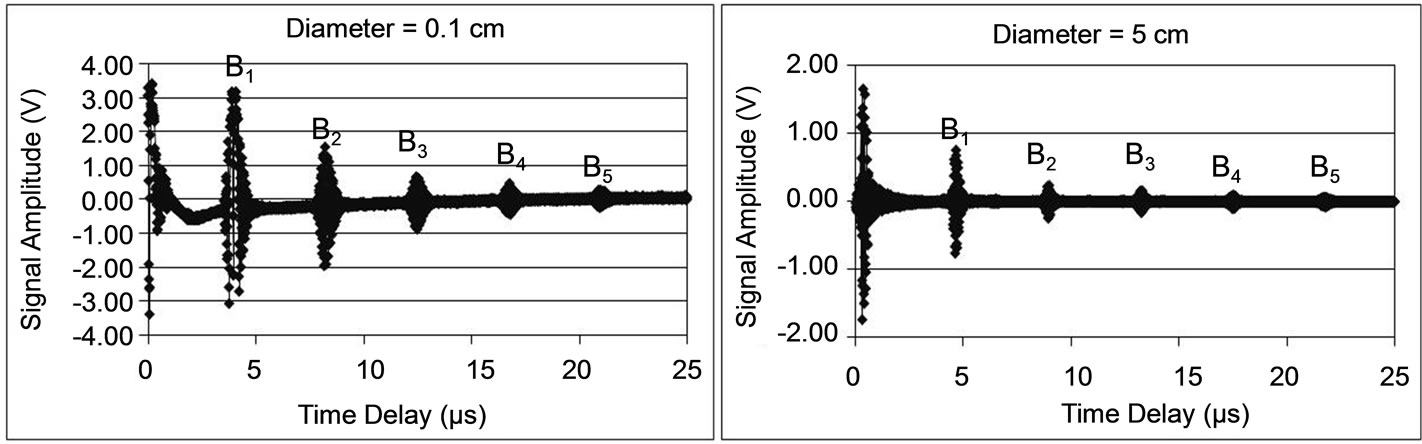
3.2. Liftoff Characterization
Next the liftoff characteristics of coils with different D and optimum N were evaluated at room temperature. Examples of the received signals reflected from the bottom
Table 1. Specifications of the trial coils.
of the 12.7-mm-thick steel plate are shown in Figure 5 (d = 0 cm) and Figure 6 (d = 20 cm). Each figure presents the results for coils with D = 0.1, 5, 10, and 20 cm inner diameter. It is shown that the received multiple thickness signals detected by a coil with a smaller inner diameter D are smaller than those with a larger D as the liftoff distance increases. As a result, a satisfactory signal for NDE can be obtained by using coils with at least 10 cm inner diameter even if the liftoff distance is more than 10 cm.
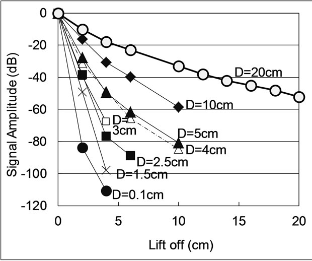
Figure 7 shows the relation between d and the amplitude of the received signal for various D. It was verified that the induction coupling coefficient increased as D increased. For example, the attenuation coefficient of the received signal for liftoff was –4.5 dB/cm for the case of D = 20 cm and –40 dB/cm when D = 0.1 cm. According to Equation (5), the magnetic field generated by a coil with a diameter of 0.1 cm decreases by –60 dB when d increases from 0 to 5 cm, leading to a signal strength loss of 120 dB, that is, –24 dB/cm, when the EM wave is assumed to travel back and forth between Coil-1 and Coil-2. Similarly, the magnetic field generated by a coil with a diameter of 20 cm decreases by –35 dB when d increases from 0 to 20 cm, leading to a loss of –70 dB per 20 cm, that is, –3.5 dB/cm.
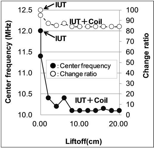
It was also observed that the center frequency and frequency bandwidth with the coil with 20 cm inner diameter decreased when d increased as shown in Figure 8. Compared with the signal induced by the IUT without coils, the center frequency and bandwidth decreased when the IUT was connected to the coils. Also, the center frequency and bandwidth decrease when d increases from 0 to 4 cm, above which they became stable. It is also confirmed that the electrical inductance of the coil with 20 cm inner diameter increases by 40% when liftoff increased from 0 to 4 cm, above which it became saturated.
 (a)
(a)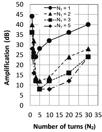 (b)
(b)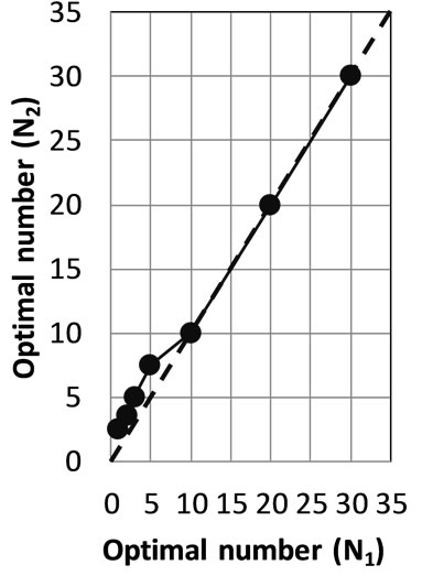 (c)
(c)
Figure 4. Optimization of the number of turns of the test coil comprising two coils. (a) Signal amplitude dependence on N1; (b) Signal amplitude dependence on N2; (c) Relationship between the optimal values of N1, N2.
 (a)
(a)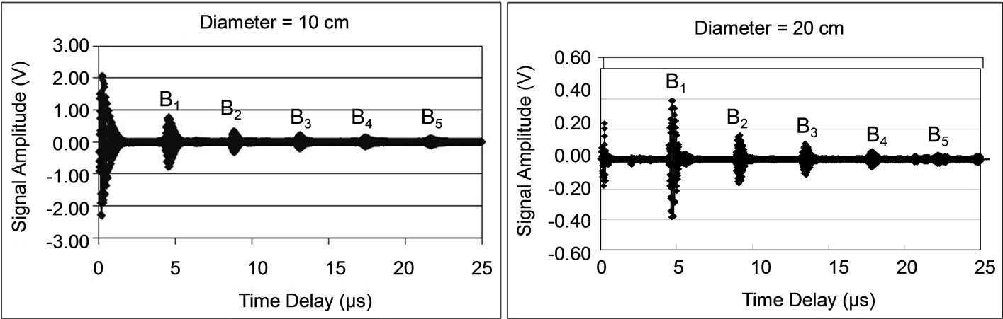 (b)
(b)
Figure 5. Examples of received ultrasonic signals when liftoff = 0 cm.
These results indicate that the received signal tends to have a lower center frequency and narrower bandwidth as the impedance of the coil increases.
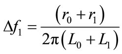
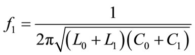
An ultrasonic signal with a narrow frequency bandwidth is less desirable for the application of this technique to NDE. Considering an IUT (L0, C0, r0) and coil (L1, C1, r1) as an electric device, the resonance frequency and bandwidth can be expressed as Equation (6). Equation (6) shows that the center frequency and frequency bandwidth of the ultrasonic signal decrease as the electrical inductance increases. However, the bandwidth is more sensitive than the center frequency to a change in electrical inductance, indicating that the reduction in bandwidth may be suppressed if the coils can be made with low inductance. To change the inductance of the EM coils copper wires of different diameters, dcopper, were used. Figure 9 shows experimental results for the relationship between the spectral characteristic and dcopper. It
 (a)
(a)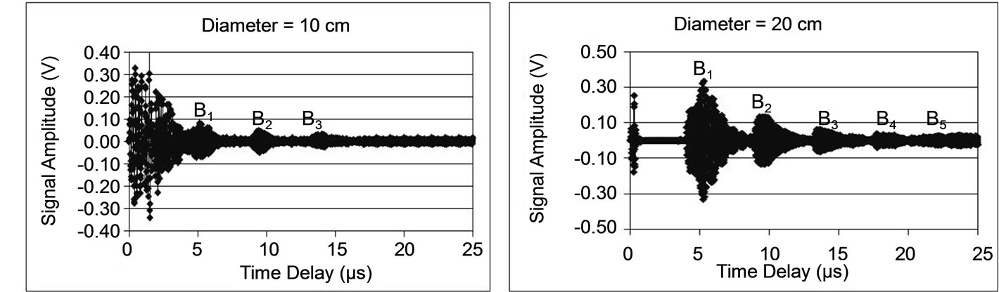 (b)
(b)
Figure 6. Examples of received ultrasonic signals when liftoff = 20 cm.
 (a)
(a)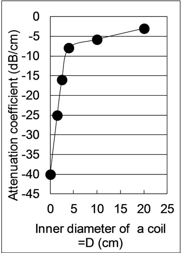 (b)
(b)
Figure 7. Liftoff characteristics. (a) Signal amplitude; (b) Signal attenuation coefficient for different liftoff distances.
is demonstrated that it is possible to use copper wires of large dcopper for EM coils to prevent the reduction of the frequency bandwidth of the received ultrasonic signals.
 (6)
(6)
 (7)
(7)
L0, C0, r0: Inductance, capacitance and resistance of IUT.
L1, C1, r1: Inductance, capacitance and resistance of coil.
3.3. Dependence of the Received Ultrasonic Signal on the Temperature
The signal amplitude was confirmed when the IUT with the EM induction coil was heated. Figure 10 shows the procedure of the experiment. First, only the IUT was heated. Next, only the coil was heated. Finally, the IUT and the coil were heated at the same time with a liftoff of 10 cm. Figure 11 shows the results of the experiment.
 (a)
(a)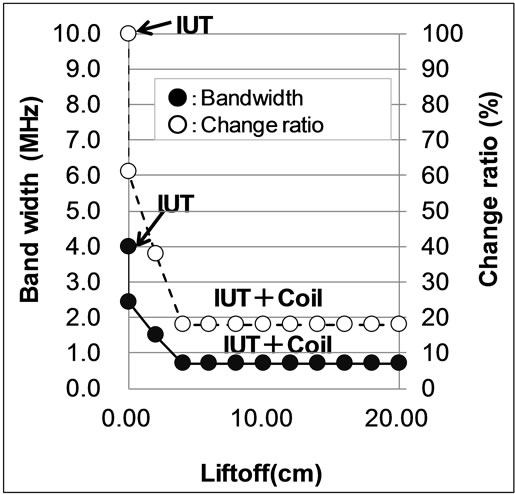 (b)
(b)
Figure 8. Spectral characteristics (D = 20 cm). (a) Center frequency; (b) Bandwidth.
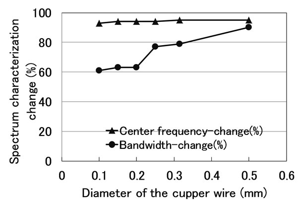
Figure 9. Dependence of spectral characteristics on the coil diameter.
The received signal was able to be observed up to 200˚C using only the IUT, and the change in the signal strength was about –8 dB. Moreover, when only the coil was heated, no change in sensitivity was observed. Finally, when the coil and the IUT were heated simultaneously, the change in the received signal was the same as that when only the IUT was heated. A PZT-IUT that can operate up to about 200˚C was used in this experiment [15]. Assuming that a BIT/PZT-IUT and a LiNbO3/PZT-IUT can operate above 400˚C, this result indicates that it is possible to perform remote sensing at several hundred Celsius.
3.4. Ferrite Core
It is desirable that the received signal strength is as high as possible when the sensing system is applied in an operating field as like a nuclear reactor. Thus, a test was carried to determine whether a ferrite core could be useful. It is known that a ferrite disc should induce and enhance magnetic fields. However, it is not clear that a ferrite core can operate at a liftoff of more than 10 cm. This was investigated using the setup shown in Figure 12. As a result of using a ferrite disk, the received signal strength was enhanced by about 10 dB as shown in Figure 12.
4. Conclusions
IUTs with a center frequency of approximately 10 MHz using PZT powders have been fabricated by a sol-gel spray method for HT NDE applications as a first step toward achieving the remote inspection of HT pipes covered a protection layer. The preliminary results of an induction-type noncontact method of ultrasonic sensing using two electrical coils for an IUT deposited onto a steel plate were presented. In this investigation the coils used were made of copper wires with lacquer coatings. The ultrasonic signals traversing back and forth in a 12.7-mm-thick steel plate were successfully detected with acceptable signal quality even when the liftoff distance exceeded 20 cm. To improve the liftoff characteristic, it is effective to increase the internal diameter of the circular
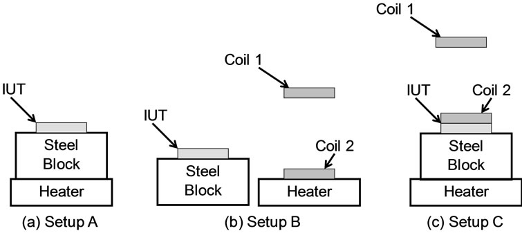
Figure 10. Procedure of the temperature dependence test.
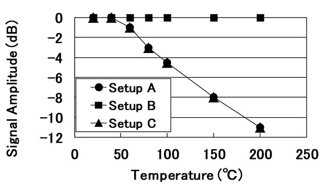
Figure 11. Dependence of the received signal amplitude of the IUT driven by an induction coil.
 (a) (b)
Figure 12. Enhancement of the received signal by employing a ferrite disc. (a) Signal strength without a ferrite disc; (b) Signal strength with a ferrite disc.
coils. Furthermore, it was confirmed that driving the IUT by an induction coil did not affect the temperature characteristic of the IUT up to 200˚C. However, it is necessary to adjust the electrical impedances of the coils connected to the pulser, receiver, and IUT. This means that it is necessary to reduce the number of turns of each coil as its diameter increases.
It was shown that the frequency bandwidth became narrower as the liftoff distance increased. It was also demonstrated that it was effective to use EM coils with large-diameter copper wire to prevent the reduction of the frequency bandwidth. Finally, it was shown that a ferrite disc is effective for enhancing the signal amplitude to a certain degree. It is expected that such an induction noncontact technique will be desirable for fast NDE even at elevated temperatures.
REFERENCES
- D. E. Bray and R. K. Stanley, “Nondestructive Evaluation,” CRC Press, New York, 1997.
- B. Raj, V. Rajendran and P. Palanichamy, “Science and Technology of Ultrasonics,” Alpha Science International Ltd., Oxford, 2004.
- A. McNab, K. J. Kirk and A. Cochran, “Ultrasonic Transducers for High Temperature Applications,” IEEE Proceedings of Science, Measurement and Technology, Vol. 145, No. 5, 1998, pp. 229-236. doi:10.1049/ip-smt:19982210
- T. Arakawa, K. Yoshikawa, S. Chiba, K. Muto and Y. Atsuta, “Applications of Brazed-Type Ultrasonic Probes for High and Low Temperature Uses,” Nondstrom Test Eval, Vol. 7, 1992, pp. 263-268.
- H. Karasawa, M. Izumi, T. Suzuki, S. Nagai, M. Tamura and S. Fujimori, “Development of Under-Sodium ThreeDimensional Visual Inspection Technique Using MatrixArrayed Ultrasonic Transducer,” Journal of Nuclear Science and Technology, Vol. 37, No. 7, 2000, pp. 769-779. doi:10.3327/jnst.37.769
- M. Sakamoto, T. Tabaru, M. Akiyama and H. Noma, “Development of an AE Sensor for High Temperature,” Hihakaikensa, Vol. 56, 2007, pp. 225-230.
- M. Kobayashi and C. K. Jen, “Piezoelectric Thick Bismuth Titanate/Lead Zirconate Titanate Composite Film Transducers for Smart NDE of Metals,” Smart Materials and Structures, Vol. 13, No. 4, 2004, pp. 951-956. doi:10.1088/0964-1726/13/4/033
- M. Kobayashi, C. K. Jen, Y. Ono and J. F. Moisan, “High Temperature Ultrasonic Transducers for NDT of Metals and Industrial Process Monitoring,” Canadian Institute for NDE Journal, Vol. 26, 2005, pp. 5-11.
- D. Barrow, T. E. Petroff, R. P. Tandon and M. Sayer, “Characterization of Thick Lead Zirconate Titanate Films Fabricated Using a New Sol Gel Based Process,” Journal of Applied Physics, Vol. 81, No. 2, 1997, pp. 876-885. doi:10.1063/1.364172
- D. Waller and A. Safari, “Corona Poling of PZT Ceramics and Flexible Piezoelectric Composites,” Ferroelectrics, Vol. 87, No. 1, 1998, pp. 189-195. doi:10.1080/00150198808201381
- M. Kobayashi, T. R. Olding, M. Sayer and C. K. Jen, “Piezoelectric Thick Film Ultrasonic Transducers Fabricated by a Sol-Gel Spray Technique,” Ultrasonics, Vol. 39, No. 10, 2002, pp. 675-680. doi:10.1016/S0041-624X(02)00390-6
- M. Kobayashi, C. K. Jen, Y. Ono, K. T. Wu and I. Shih, “Integrated High-Temperature Longitudinal, Shear, and Plate Acoustic-Wave Transducers,” Japanese Journal of Applied Physics, Vol. 46, 2007, pp. 4688-4692. doi:10.1143/JJAP.46.4688
- D. Greve, I. J. Oppenheim, H. Sohn, C. P. Yue and W. Wu, “An Inductively Coupled Lamb Wave Transducer,” IEEE Sensors Journal, Vol. 7, No. 2, 2007, pp. 295-301. doi:10.1109/JSEN.2006.886904
- M. Kobayashi, K. T. Wu, L. Song, C. K. Jen and N. Ad, “Structural Health Monitoring of Composites Using Integrated and Flexible Piezoelectric Ultrasonic Transducers,” Journal of Intelligence Material Systems and Structures, Vol. 20, No. 8, 2009, pp. 969-977. doi:10.1177/1045389X08101563
- M. Kobayashi, C. K. Jen, J. F. Bussiere and K. T. Wu, “High-Temperature Integrated and Flexible Ultrasonic Transducers for Nondestructive Testing,” NDT & E International, Vol. 42, No. 2, 2009, pp. 157-161. doi:10.1016/j.ndteint.2008.11.003
NOTES
*Corresponding author.