Open Journal of Modelling and Simulation
Vol.02 No.04(2014), Article ID:50369,10 pages
10.4236/ojmsi.2014.24014
On the Study of Magneto-Hydrodynamic Non-Newtonian Fluid Flow throughout Curvilinear Channel with Corrugated Walls
Seyed Ali Madani Tonekaboni1*, Hamid Reza Gharahi2, Mohammad Hossein Motevaselian3, Seyed Fouad Karimian4, Sara Jahromi5
1Department of Applied Mathematics, University of Waterloo, Waterloo, Canada
2Department of Mechanical Engineering, Michigan State University, East Lansing, USA
3Department of Mechanical Engineering, University of Illinoise at Urbana Champaign, Champaign, USA
4Department of Mechanical Engineering, University of Tehran, Tehran, Iran
5Department of Mechanical Engineering, Sharif University of Technology, Tehran, Iran
Email: *samadani@uwaterloo.ca
Copyright © 2014 by authors and Scientific Research Publishing Inc.
This work is licensed under the Creative Commons Attribution International License (CC BY).
http://creativecommons.org/licenses/by/4.0/


Received 20 July 2014; revised 23 August 2014; accepted 11 September 2014
ABSTRACT
This article aims to numerically investigate the flow pattern for Newtonian and power law non- Newtonian fluid in a semi-half circular channel with corrugated walls under the influence of a magnetic field. The results indicate that, presence of a magnetic field affects the flow field in several aspects, especially in the vortex creation and dissipation. In addition, the analysis is carried out for different Reynolds numbers to ascertain the influence of magnetic field on each flow regime. Eventually, the analysis is carried out for a range of power indices including pseudo plastic (shear-thinning) to dilatants (shear-thickening) fluids. The results show that by increasing the power-index, the vortices begin to form and grow gradually so that in the shear-thickening fluid an extra vortex is formed and created nearby the corrugated part of the channel.
Keywords:
Newtonianfluid, Power-Law Non-Newtonian Fluid, Shear-thickening, Shear-thinning

1. Introduction
Conducting numerical research on the fluid flow in complex geometries has been always essential for the design and application of different mechanisms. One sort of these mechanisms is compact heat exchangers. Since these systems have found to be very useful in a variety of usage in food, pharmaceutical industries and chemical processing [1] , many experimental and numerical researches have been conducted to fathom out more about different influential parameters on these systems. Enhancement of heat transfer in these heat exchangers is due to their corrugated geometry which is inclined to increase the rate of heat transfer by dint of producing vortices created by fluid flowing over oscillating wall. This improvement in heat transfer contributes to more efficient energy systems and lower costs in various industries.
A number of studies have been made to inspect behavior of different types of fluid flows in waved wall geometries. Phan and Khan [2] have conducted an experimental and numerical research on the flow of an oldroyd- type fluid through a sinusoidal corrugated tube. An experimental research has been done on flow of non-New- tonian fluids in corrugated channels by Yalamanchili [3] . Laminar flow heat transfer to viscous power-law fluids in double-sine ducts has been investigated by Manglik and Ding [4] . Enhanced laminar forced convection has been studied for both Newtonian and non-Newtonian fluid flows in sinusoidal corrugated plate channels by Metwally [1] . Effect of fin waviness and spacing on the vortices for air has been examined by Zhang et al. [5] and Fernandes et al. [6] researched into laminar flow in chevron-type plate heat exchangers.
In the present study, a fluid flow, passing a curved channel with corrugated walls expose to a magnetic field, has been investigated, numerically, and formation of vortices has been studied as well as other properties of flow pattern. Moreover, since the chosen geometry has a widespread usage in biological systems such as intestine and gullet, in addition to a Newtonian fluid, a power-law non-Newtonian fluid is also taken into consideration in order to draw an analogy between the former and latter fluids to ascertain whether which can be more efficacious in increasing heat transfer by creating vortices under a magnetic field. Furthermore, in the mentioned uses of compact heat exchangers, it is not necessary to assume the fluid as only a Newtonian type. It would be more inclusive to cover a wide range of actual uses in different applications by investigating the flow patterns of non- Newtonian fluids, especially a power-law model which is a simple and ubiquitous model for non-Newtonian fluids. Also, the effects of fluid rheology are considered in the study, including shear thinning and thickening behavior.
2. Problem Statement
The 2D flow geometry which is considered in this work is illustrated in Figure 1. Flow uniformly in y-direction enters the curved channel from inlet and after passing through the corrugated walls exits from outlet. Meanwhile, a magnetic field is imposed on fluid flow. The average width of the channel is 1cm and the amplitude of the wavy wall is 0.2 cm. Walls of the channel are assumed to be solid and follow a sinusoidal pattern around the curvature of the channel. For better capturing the flow pattern, especially the creation of secondary flows nearby the curvatures, the mesh employed in this paper is considered to be unstructured by being refined adjacent to the sinusoidal curvatures of the geometry. Figure 2 magnifies a part of the grid used for solution.
3. Mathematical Modeling
3.1. Governing Equations
In the first step, it is necessary to mention the governing equations. Because of employing different fluid models, including Newtonian and power-law fluid, Cauchy equations are used for obtaining momentum equations. Two dimensional Cauchy equations for modeling the fluid flow are given by:
 (1)
(1)
 (2)
(2)
And the continuity equation is written in a form of incompressible fluid:
 (3)
(3)

Figure 1. Schematic of flow geometry.

Figure 2. Mesh-grid throughout one period of sinusoidal walls.
where  and
and  are the velocity components in x- and y-directions. In both Equations (1) and (2)
  embodies the body force which is imposed by a magnetic field and affects the fluid flow, in this problem. According to Maxwell’s relations simplified by the assumption of spatial independency of magnetic field, magnetic force can be procured as:
 (4)
(4)
where  is the magnetic flux intensity,
  is electrical conductivity,
  is velocity vector and
  is current density which can be expressed as follow by Ohm’s law:
 (5)
(5)
 , magnetic flux intensity, consists of two components: external magnetic field
  and induced magnetic fields
 .
.
 (6)
(6)
The magnetic Reynolds number is assumed to be very small so that the induced magnetic field and Hall Effect are negligible [7] . One of the consequences of small magnetic Reynolds number is the uncoupling of the Cauchy equations from Maxwell’s equation. In addition, the imposed and induced electrical fields are also assumed to be negligible. In this article, external magnetic field is considered to be constant and exerted on the flow domain in two perpendicular directions x and y.
 (7)
(7)
where  and
and  are components of magnetic field in the x- and y-directions, respectively. By implementing this in (4) electromagnetic field can be easily calculated in the Cartesian coordinates as:
 (8)
(8)
where the first term is considered  in Equation (1) and the second one is considered
  in Equation (2). Two auxiliary parameters are defined to simplify the procedure of obtaining suitable results. These parameters, which determine the value of magnetic field in x- and y-directions, are presented in following relations:
 (9)
(9)
 (10)
(10)
Due to the fact that the flow is contemplated steady and regarding these auxiliary parameters, Equations (1) and (2) can be rewritten in the form of the Equations (11) and (12).
 (11)
(11)
 (12)
(12)
The shear stress terms in the above equations, vary according to the type of fluid. For Newtonian fluids, the equations turn into Navier-Stokes equation and for power-law fluids, the shear stress is proposed as follow:
 (13)
(13)
By changing the parameters ,  etc. sundry kind of fluids modeled by each approach, can be applied to the solution. Moreover, it is obvious that for
 , power-law fluid transform to Newtonian fluids.
3.2. Boundary conditions
Flow enters the channel with a uniform profile in y-direction. So boundary conditions at inlet are:
 (14)
(14)
By implementing no-slip condition on the solid walls, boundary conditions on walls can be written as:
 (15)
(15)
For the boundary conditions at the outlet, a channel has been added after the outlet of geometry long enough to develop the flow to its fully-developed state. Therefore, at the outlet, the boundary condition is considered fully-developed condition.
4. Results and discussion
4.1. Newtonian fluid
In the following section, first solutions for a Newtonian fluid flow with  subjected to different magnetic fields are presented and then these effects are studied by investigation of the magnetic field direction’s effect on axial velocity profile in different
  numbers. According to Equations (9) and (10), a and b represent the x-direction and y-direction component of the magnetic field respectively.
Figure 3 portrays the effects of the magnetic field on the fluid flow. Figure 3(a) shows the streamlines for a flow passing the geometry without magnetic field, which both components of the magnetic field are zero. It is

Figure 3. Stream lines for flow in different magnetic fields (a)  (b)
(b)  (c)
(c)  (d)
(d)
obvious that in the lack of magnetic field, the vortices form in all of the peaks of the geometry and the main stream moves through the channel and follows its curvature. In the Figure 3(b), the vertical component of the magnetic field is zero but the horizontal component exists. In accordance with Equation (4), the flow is supposed to be influenced by magnetic field  where the velocity direction of the flow is at an angle with the magnetic field vector. This happens near the inlet and the outlet of the channel where flow is approximately vertical. However, where the velocity direction is horizontal, in the middle area of the channel, the flow is supposed to be less affected by the magnetic field. These theoretical approaches are in complete congruity with the streamlines displayed in Figure 3(b).
At the inlet and outlet area of the channel, the vortices are disappeared. In the middle of the channel, where velocity direction is aligned with the magnetic field, the magnetic field has fewer effects on the flow field and the vortices are formed almost similar to that of the flow field with no magnetic field. By changing the direction of the flow field into vertical direction, Figure 3(c), the location of vortices alters. The same explanation exists for this case: where the stream lines are normal to the magnetic field vector, the influence of the magnetic field is maximized and where they are in the same direction, especially at the inlet and outlet area, the influence is minimized. Figure 3(d) belongs to the flow which influenced by a magnetic in both directions equally. Again, considering the direction of the fluid’s velocity, the effects of the magnetic field vary in different areas of the channel. It is clear from this figure that the number of the vortices has been reduced to two vortices which are near each other and the streamlines are lined up with magnetic field vector in this region of the channel. From the figures above, it can be concluded that the flow pattern and the location of the vortices can be controlled by imposing magnetic field in the suitable direction regarding the application.
Figure 4 surveys the effect of magnetic field on axial velocity in a section A represented in Figure 1. The magnitudes of different inlet velocities investigated are  and
and  which embody Re numbers of 100, 200, 300, 400 and 500, respectively. Figure 4(a) is the diagram of axial flow in channel in the mentioned section. As it can be observed in the figure, flow is approximately axisymmetric and back flow exists in various inlet velocities. However, by increasing the velocity at the inlet, the back flow velocity increases and the velocity gradient rises. By imposing magnetic field horizontally, Figure 4(b), the velocity
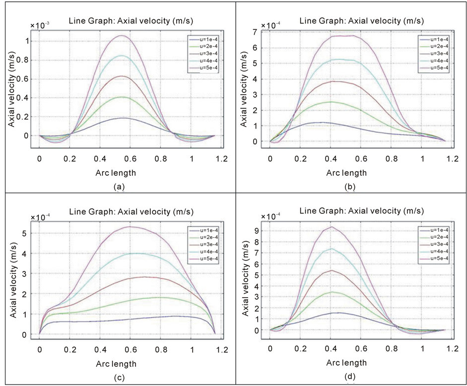
Figure 4. Diagram of the axial velocity for flow for with different inlet velocities in various magnetic fields (a)  (b)
(b)  (c)
(c)  (d)
(d)
profile changes with respect to the direction of the magnetic field. This figure illustrates that magnetic field causes the velocity profile to be less sharp and the back flow disappears in low velocities and in the higher velocities the velocity of the back flow reduces considerably. In Figure 4(c) where magnetic field is imposed vertically, velocity profile is almost uniform in the most of the width of the channel for lower velocities and for higher velocities the maximum velocity is almost half of its value of the case without magnetic field. When both components of the magnetic field are present in the chosen section, the variance caused by magnetic field is obvious in Figure 4(d). The back flow for lower inlet velocities is omitted in one side, but overall, the profiles are similar to the first one. Regarding this and the fact that in this case the axis of the channel is nearly in the same direction with magnetic field vector, it can be concluded that magnetic has fewer effect on the velocity profile in this section than previous cases. As a result, it can be determined that by inducing a suitable magnetic field, regarding the usage, on the fluid flow in the channel, it is possible to exact the flow to follow the desired patterns, to sharpen or weaken the velocity profile and to control the location and size of vortices.
4.2. Power-law
4.2.1. Magnetic Field’s Effect on Power-Law Fluid
In this section, power-law fluid flow is investigated using the Equation (13) with assumption of constant fluid characteristics including  and
and . Hence, the effects of variation of magnetic field’s strength are investigated in this section for the fluid with these features.
Figure 5 shows the stream lines for fluid flow for different magnetic fields. Lacking the magnetic field, flow passes the channel in a simple pattern and vortices form in all corrugations of the walls, Figure 5(a). By applying a magnetic field on the flow, the flow pattern will definitely change. According to Figure 5(b) and Figure 5(c) where a horizontal or vertical magnetic field is applied on the flow, the changes in the areas which the velocity direction is normal to the magnetic field vector . Similar to the previous section, this phenomenon can be justified by Equation (4). The effects of a bi-directional magnetic field is alike the previous section too, Figure 5(d). Thus, overall effects of magnetic field for different fluid flows are the same. However, details vary in each case. Though, it seems that magnetic field has influenced the power-law fluid more, in Figure 5(b), the vortices are vanished in fourth period of the wavy pattern of the wall, but in Figure 4(b), vortices partly exist in this period. Moreover, the size of the vortices relevant to their corresponding when magnetic field is absent diminishes more in power-law fluid. Figure 6 shows the axial velocity profile in a section of the channel. To make a reasonable analogy with Figure 4, the inlet velocities are the same in both plots.
Figure 6(a) examines the axial velocity profile in the selected section while magnetic field is lacking. Existence of back flow is obvious in this figure; near the walls, the axial velocity of the flow is in the opposite direction of its velocity in the middle of the channel for higher velocities. Though, when the inlet velocity increases, in the area adjacent to the outer wall, the direction of the axial velocity alters again. This deviation from the profile obtained for Newtonian flow, Figure 4(a), can be justified by the non-Newtonian behavior of the flow, determined by power-law correlation for viscosity (Equation (13)). In the subsequent section this behavior and its influential parameters will be discussed further.
In the next figures, the effect of one dimensional magnetic fields on velocity profile are investigated in Figure 6(b) and Figure 6(c). When flow is subject to a horizontal magnetic field, as it is obvious in Figure 6(b), the back flow disappears in one side for higher inlet velocities but it remains existent in the other side. One the other hand, when a vertical magnetic field is imposed, the backflow in both sides disappears. Figure 6(c). Besides, the maximum magnitude of axial velocity reduces in both cases and the velocity gradient diminishes in the middle area of the channel’s width, and in some velocities, especially lower ones, the velocity profile becomes uniform

Figure 5. Stream lines for power-law fluid flow in different magnetic fields (a)  (b)
(b)  (c)
(c)  (d)
(d)
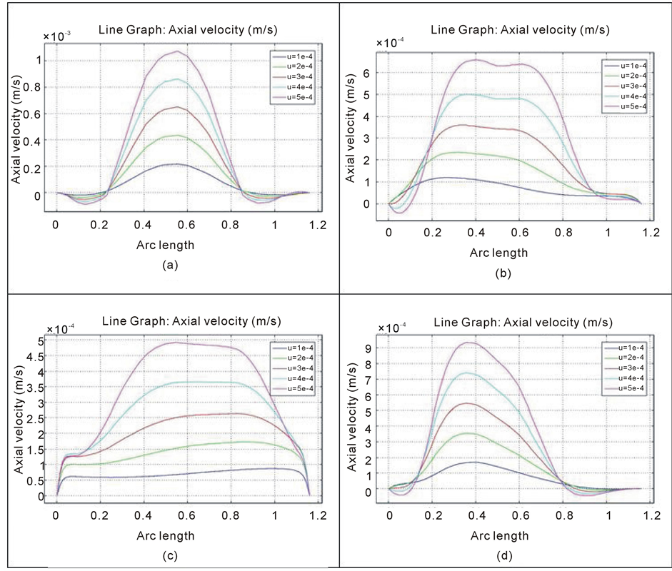
Figure 6. Diagram of the axial velocity for power-law fluid flow in different magnetic fields (a)  (b)
(b)  (c)
(c)  (d)
(d)
in a great portion of the section. Again, these effects are similar for a Newtonian fluid flow, but the differences in slope of the profile, maximum velocity both in main flow and back flow and velocity gradient especially near the walls are clear. Figure 6(d) embodies the axial velocity profile in a bi-directional magnetic field. The backflows near the walls appear again, the profile is similar to the first case, but the peak has been relocated and for lower velocities, backflow doesn’t occur. As a conclusion, the effect of magnetic field on Newtonian and non-Newtonian fluid flows are generally the same, and the alterations happens in details, as a result of difference in viscosity. Viscosity in power-law fluids differs in different regions according to the gradient of velocity in those regions, and this causes differences in the pattern of flow in comparison with Newtonian flow.
4.2.2. Power index Effect on Power-lawfluid flow
In power-law fluids, according to Equation (13), two parameters are influential:  and n. Typically, behavior of a fluid is characterized by a value of
  power-law index. Fluid shows shear-thinning behavior when power- law index is less than unity, and express shear-thickening behavior when it is more than unity. In the case of
  as mentioned in 0, fluid turns into a Newtonian fluid. In this section, flow pattern in the geometry will be discussed for different power-law indices. In all cases in Figure 7 the inlet velocity magnitude is assumed same as the highest value considered for Newtonian fluid resulted in Re = 500.
When the power-law index equals to 0.6, Figure 7(a), no vortex is created. The flow passing the geometry

Figure 7. Streamlines of power-law fluid flow passing channel (a)  (b)
(b)  (c)
(c)  (d)
(d)
near the walls follows the curvature and no backflow or separation happens. By increasing  to 0.8, Figure 7(b), although the fluid is considered shear-thinning, flow pattern changes dramatically. Vortices shape in wavy outline of the walls and the flow pattern is similar to Newtonian flow pattern. Figure 7(c). The case of
  has been discussed in Section 4.1. Vortices appear in all corrugation of walls and flow follows the curvature pattern in the middle area. Figure 7(d) delineates the effect of increasing
  to 1.2, in which the fluid is supposed to show shear-thickening behavior. As it can be seen in the figure, fluid flow follows the curvature in the middle area, similar to others, but in wavy patterns of upper walls, two vortices have formed. However, in each of the lower wall’s corrugations, one vortex has shaped. This occurrence illustrates that in this specified geometry shear-thickening behavior of the fluid compels it to follow a more complex pattern than other fluids. Next figure, Figure 8, examines different inlet velocities for four power indices of 0.6, 0.8, 1 and 1.2.
According to Figure 8(a), backflow doesn’t appear in the fluid flow. The velocity increases from its zero value on the walls smoothly, reaches its peak, approximately in the middle of the channel’s width and then decrease to the zero, adjacent to wall. The similar behavior when n is 0.8 and the velocity is low, but by increasing velocity in this case, backflow starts to appear in the section and regarding the velocity magnitude in this backflow, the maximum velocity in this section rises in analogy with the previous case, Figure 8(b). For  backflow exists in a wide range of velocities and it occupies a greater portion of the section, so the maximum velocity and slope of profile is more, Figure 8(c). Increasing power index to 1.2 causes some alteration in profiles, Figure 8(d). First, backflows grow especially in the outer walls neighborhood. Second, when inlet velocity increases, velocity becomes positive before reaching its value of zero. Moreover, the magnitude of velocity in backflows upsurges and the gradient of velocity rises well. To recapitulate, the fluid flow is very sensitive and dependent on power-law index, by changing this value even in shear-thinning fluids important changes appear and when this value exceeds unity, the flow shows an intricate behavior in following channels pattern.
5. Conclusions
In this study, the COMSOL software is employed to model two different kinds of fluids, Newtonian and

Figure 8. Axial velocity profile in a section of the geometry (a)  (b)
(b)  (c)
(c)  (d)
(d)
power-law non-Newtonian fluid, in a semi half circular corrugated wall, in order to investigate the flow pattern in such geometry under the influence of a magnetic field. In the view of the results following findings may be summarized.
First, the change in the flow pattern under the influence of the magnetic field is highly dependent on the direction of the fluid velocity and magnetic forces exerted on the flow field. It has been shown that, the impact of the magnetic field in the areas that the fluid velocity is aligned with the magnetic forces is low. On the other hand, when the streamlines are perpendicular to the forces, the influence of the magnetic field reaches to its culmination and results in dissipation of the vortices.
Second, in addition to the effects of magnetic field, Reynolds number is also another influential parameter in changing the flow pattern, especially at the outlet of the channel. The results indicate that, without the presence of magnetic field, increasing the Reynolds number intensifies the backflow velocity, however, by imposing the external magnetic forces in a specific and desired directions, the growth in backflow velocity can be controlled.
Finally, for the power-law fluid, by increasing the power indices including shear-thinning to shear-thickening fluid, the sizes of vortices seems to grow and eventually in the shear-thickening fluid an extra vortex forms due to its power index.
References
- Metwally, H.E.M.H. (2002) A Computational Study of Enhanced Laminar Forced Convection Heat Transfer to Newtonian and Non-Newtonian Fluid Flows in Sinusoidal Corrugated-Plate Channels. Ph.D. Dissertation, University of Cincinnati, Cincinnati.
- Phan-Thien, N. and Khan, M.M.K. (1987) Flow of an Oldroyd-Type Fluid through a Sinusoidally Corrugated Tube. Journal of Non-Newtonian Fluid Mechanics, 24, 203-220. http://dx.doi.org/10.1016/0377-0257(87)85010-3
- Yalamanchili, R.C. (1993) Flow of Non-Newtonian Fluids in Corrugated Channels. International Journal of Non- Linear Mechanics, 28, 535-548. http://dx.doi.org/10.1016/0020-7462(93)90046-N
- Manglik, R.M. and Ding, J. (1997) Laminar Flow Heat Transfer to Viscous Power-Law Fluids in Double-Sine Ducts. International Journal of Heat and Mass Transfer, 40, 1379-1390. http://dx.doi.org/10.1016/S0017-9310(96)00185-8
- Zhang, J.H., Kundu, J. and Manglik, R.M. (2004) Effect of Fin Waviness and Spacing on the Lateral Vortex Structure and Laminar Heat Transfer in Wavy-Plate-Fin Cores. International Journal of Heat and Mass Transfer, 47, 1719-1730. http://dx.doi.org/10.1016/j.ijheatmasstransfer.2003.10.006
- Fernandes, C.S., Dias, R.P., Nóbrega, J.M. and Maia, J.M. (2007) Laminar Flow in Chevron-Type Plate Heat Exchangers: CFD Analysis of Tortuosity, Shape Factor and Friction Factor. Chemical Engineering and Processing: Process Intensification, 46, 825-833. http://dx.doi.org/10.1016/j.cep.2007.05.011
- Cramer, K.R. and Pai, S.I. (1973) Magnetofluid Dynamics for Engineers and Physicists. McGraw-Hill, New York.
NOTES

*Corresponding author.