Open Journal of Modelling and Simulation
Vol. 1 No. 2 (2013) , Article ID: 30725 , 10 pages DOI:10.4236/ojmsi.2013.12003
Using Automation Controller System and Simulation Program for Testing Closed Circuits of Mini-Sprinkler Irrigation System
1Water Relations Field Irrigation Department, Agricultural and Biological Division, National Research Center, Cairo, Egypt
2Soil and Water Resources Conservation Department, Desert Research Center, Cairo, Egypt
3Irrigation Department, Agriculture Engineering Research Institute, Agricultural Research Center, Cairo, Egypt
Email: *mansourhani2011@gmail.com
Copyright © 2013 Hani A. Mansour et al. This is an open access article distributed under the Creative Commons Attribution License, which permits unrestricted use, distribution, and reproduction in any medium, provided the original work is properly cited.
Received February 18, 2013; revised March 25, 2013; accepted April 1, 2013
Keywords: Automation; Controller; Simulation; Program; Mini-Sprinkler; Irrigation; Lateral; Closed; Circuits
ABSTRACT
The field experiments were conducted at the experimental farm of Faculty of agricultural, southern Illinois University SIUC, USA. The project makes the irrigation automated. With the use of low cost sensors and the simple circuitry makes currently project a low cost product, which can be bought even by a poor farmer. This research work is best suited for places where water is scares and has to be used in limited quantity and this proposal is a model to modernize the agriculture industries at a mass scale with optimum expenditure. In the field of agricultural engineering, use of sensor method of irrigation operation is important and it is well known that closed circuits of Mini-sprinkler irrigation system are very economical and efficient. Closed circuits are considered one of the modifications of Mini-sprinkler irrigation system, and added advantages to Mini-sprinkler irrigation system because it can relieve low operating pressures problem at the end of the lateral lines. In the conventional closed circuits of Mini-sprinkler irrigation system, the farmer has to keep watch on irrigation timetable, which is different for different crops. Using this system, one can save manpower, water to improve production and ultimately profit. The data could be summarized in following: Irrigation methods under study when using lateral length 60 m could be ranked in the following ascending order according the values of the predicted and measured head losses CM1M-SIS < CM2M-SIS.The correlation (Corr.) coefficients were used to compare the predicted and measured head losses along the lateral lines of all the closed circuits designs. Generally, the values of correlation analysis were (>0.90) were obtained with 0% field slope 60 m length (experimental conditions) for all closed circuits.The interaction between irrigation methods: at the start there are significant differences between CM2M-SIS and CM1M-SIS.
1. Introduction
The continuous increasing demand of the food requires the rapid improvement in food production technology. In a country like India, where the economy is mainly based on agriculture and the climatic conditions are isotropic, still we are not able to make full use of agricultural resources. The main reason is the lack of rains & scarcity of land reservoir water. The continuous extraction of water from earth is reducing the water level due to which lot of land is coming slowly in the zones of un-irrigated land. Another very important reason of this is due to unplanned use of water due to which a significant amount of water goes waste. In the modern closed circuits of Mini-sprinkler irrigation system systems, the most significant advantage is that water is supplied near the root zone of the plants Mini-sprinkler by Mini-sprinkler due to which a large quantity of water is saved. At the present era, the farmers have been using irrigation technique in India through the manual control in which the farmers irrigate the land at the regular intervals. This process sometimes consumes more water or sometimes the water reaches late due to which the crops get dried. Water deficiency can be detrimental to plants before visible wilting occurs. Slowed growth rate, lighter weight fruit follows slight water deficiency. This problem can be perfectly rectified if we use automatic micro controller based closed circuits of Mini-sprinkler irrigation systemin which the irrigation will take place only when there will be intense requirement of water.
Irrigation system uses valves to turn irrigation ON and OFF. These valves may be easily automated by using controllers and solenoids. Automating farm or nursery irrigation allows farmers to apply the right amount of water at the right time, regardless of the availability of labor to turn valves on and off. In addition, farmers using automation equipment are able to reduce runoff from over watering saturated soils, avoid irrigating at the wrong time of day, which will improve crop performance by ensuring adequate water and nutrients when needed. Automatic Closed circuits of Mini-sprinkler irrigation system is a valuable tool for accurate soil moisture control in highly specialized greenhouse vegetable production and it is a simple, precise method for irrigation. It also helps in time saving, removal of human error in adjusting available soil moisture levels and to maximize their net profits.
The entire automation work can be divided in two sections, first is to study the basic components of irrigation system thoroughly and then to design and implement the control circuitry. So we will first see some of the basic platform of closed circuits of Mini-sprinkler irrigation system (Figure 1).
1.1. Definition of Irrigation
Irrigation is the artificial application of water to the soil usually for assisting in growing crops. In crop production it is mainly used in dry areas and in periods of rainfall shortfalls, but also to protect plants against frost.
1.2. Types of Irrigation
Surface irrigation, Localized irrigation (Drip, mini sprinkler, bubbler, etc.), Closed circuits of Mini-sprinkler irrigation system and Sprinkler irrigation.
Closed circuits of Mini-sprinkler irrigation system also known as Mini-sprinkler irrigation system or micro-irrigation is an sprinkler irrigation method which minimizes the use of water and fertilizer by allowing water to Minisprinkler slowly to the roots of plants, either onto the soil surfaceor directly onto the root zone, through a network of valves, pipes, tubing, and emitters., [1].
1.3. Concept of Modern Irrigation System
The conventional irrigation methods like overhead sprinklers, flood type feeding systems usually wet the lower leaves and stem of the plants. The entire soil surface is saturated and often stays wet long after irrigation is completed. Such condition promotes infections by leaf mold fungi. The flood type methods consume large amount of water and the area between crop rows remains dry and receives moisture only from incidental rainfall. On the contrary the Mini-sprinkler or closed circuits of Minisprinkler irrigation system is a type of modern irrigation technique that slowly applies small amounts of water to part of plant root zone. Closed circuits of drip irrigation system are invented by the Egyptian thesis of researcher Hani Mansour, 2010s [2]. Water is supplied frequently, often daily to maintain favorable soil moisture condition and prevent moisture stress in the plant with proper use of water resources.
Closed circuits of Mini-sprinkler irrigation system save water because only the plant’s root zone receives moisture. Little water is lost to deep percolation if the proper amount is applied. Closed circuits of Mini-sprin-
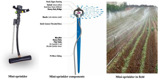
Figure 1. Min-sprinkler irrigation system.
kler irrigation system are popular because it can increase yields and decrease both water requirements and labor. Closed circuits of drip irrigation system require about half of the water needed by sprinkler or surface irrigation. Lower operating pressures and flow rates result in reduced energy costs. A higher degree of water control is attainable. Plants can be supplied with more precise amounts of water. Disease and insect damage is reduced because plant foliage stays dry [2]. Operating cost is usually reduced. Federations may continue during the irrigation process because rows between plants remain dry. Fertilizers can be applied through this type of system. This can result in a reduction of fertilizer and fertilizer costs. When compared with overhead sprinkler systems, closed circuits of Mini-sprinkler irrigation system lead to less soil and wind erosion. Closed circuits of Mini-prinkler irrigation system can be applied under a wide range of field conditions. A typical closed circuits of drip irrigation system assembly is shown in Figures 2 and 3 below [1]. The goal of this study is to design and simulate a new solution for modernizing the irrigation operation of agriculture industries.
2. Material and Methods
The field experiments were conducted at the experimental farm of Faculty of agricultural, southern Illinois University SIUC, USA. The design of field experiments was split in randomized complete block design with three replicates. The field tests carried out using line length 60m and the following tow Mini-sprinkler irrigation circuits (DIC): 1) one manifold for lateral lines or closed circuits with one manifold of Mini-sprinkler irrigation system (CM1M-SIS) and 2) closed circuits with two manifolds for lateral lines (CM2M-SIS) Figures 2 and 3.
Irrigation networks include the following components are:
1) Control head: It was located at the water source
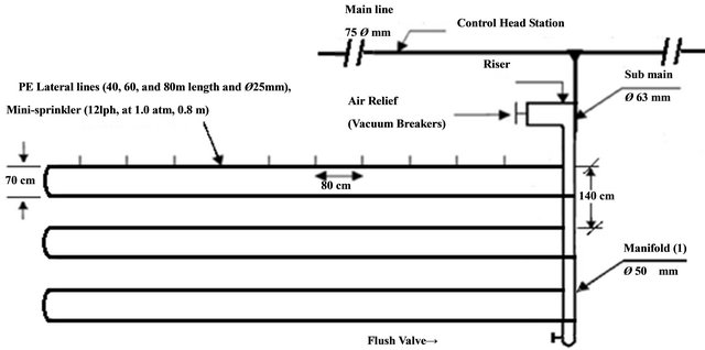
Figure 2. Layout of mini-sprinkler closed circuits with one manifold (CM1M-SIS) for lateral lines.
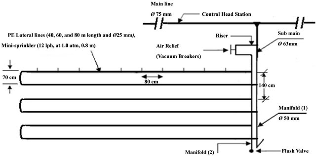
Figure 3. Layout of mini-sprinkler closed circuit with two manifolds (CM2M-SIS) for lateral lines.
supply. It consists of centrifugal pump 3''/3'', driven by electric engine (pump discharge of 80 m3/h and 40 m lift), sand media filter 48'' (two tanks), screen filter 2'' (120 mesh), back flow prevention device, pressure regulator, pressure gauges, flow-meter, control valves and chemical injection; 2) Main line: PVC pipes of 75 mm in (ID) Ø to convey the water from the source to the main control points in the field; 3) Sub-main lines: PVC pipes of 75mm in (ID) Ø were connected to with the main line through a control unit consists of a 2'' ball valve and pressure gauges; 4) Manifold lines: PVC pipes of 50 mm in (ID) Ø were connected to the sub main line through control valves 1.5''; 5) Lateral lines: PE tubes of 25 mm in (ID) Ø were connected to the manifolds through beginnings stalled on manifolds lines; 6) Mini-sprinklers: These online PE tubes 25mm in (ID) Ø, mini sprinkler discharge of 12 lh−1 at 1 atm, Operating pressure and 50 cm spacing in-between [1].
The components of closed circuits of the Mini-sprinkler system include, supply lines, control valves, supply and return manifolds, Mini-sprinkler lateral lines, emitters, check valves and air relief valves/vacuum breakers.
2.1. Irrigation Scheduling
Intervals of irrigation (I) in day were calculated using the following equations:
I = d/Etc (1)
Where: d = net water depth applied per each irrigation (mm), and Etc = crop evapotranspiration (mm/day).
d = AMD·ASW·Rd·P (2)
Where: AMD = allowable soil moisture depletion (%), ASW = available soil water, (mm water/m depth), Rd = effective root zone depth (m), or irrigation depth (m), and P = percentage of soil area wetted (%).
AW (v/v %) = ASW (w/w %)·B.D. (3)
Where: B.D. = Soil bulk density (gm·cm−3).
Irrigation Intervals used was 4 days under both closed circuits of Mini-sprinkler irrigation systems.
Design of automation controller based closed circuits of Mini-sprinkler irrigation system: (presented for Drip irrigation by [3]:
The key elements that should be considered while designing a mechanical model.
Pressure (The force pushing the flow): Most products operate best between 1.0 and 1.5 bars of pressure. Normal household pressure is 10 m (1.0 bar).
Water Supply & Quality: City and well water are easy to filter for closed circuits of Mini-sprinkler irrigation system systems. Pond, ditch and some well water have special filtering needs. The quality and source of water will dictate the type of filter necessary for your system.
Flow: We can measure the output of your water supply with a one or five gallon bucket and a stopwatch. Time how long it takes to fill the bucket and use that number to calculate how much water is available per hour. Gallons per minute × 60 = number of gallons per hour.
Elevation: Variations in elevation can cause a change in water pressure within the system. Pressure changes by one pound for every 2.3 foot change in elevation. Pressure-compensating emitters are designed to work in areas with large changes in elevation.
Soil Type and Root Structure: The soil type will dictate how a regular Mini-sprinkler of water on one spot will spread. Sandy soil requires closer emitter spacing as water percolates vertically at a fast rate and slower horizontally. With a clay soil water tends to spread horizontally, giving a wide distribution pattern. Emitters can be spaced further apart with clay type soil. A loamy type soil will produce a more even percolation dispersion of water. Deep-rooted plants can handle a wider spacing of emitters, while shallow rooted plants are most efficiently watered slowly (low gap emitters) with emitters spaced close together. On clay soil or on a hillside, short cycles repeated frequently work best. On sandy soil, applying water with higher gap emitters lets the water spread out horizontally better than a low gap emitter.
Timing: Watering in a regular scheduled cycle is essential. On clay soil or hillsides, short cycles repeated frequently work best to prevent runoff, erosion and wasted water. In sandy soils, slow watering using low output emitters is recommended. Timers help prevent the toodry/too-wet cycles that stress plants and retard their growth. They also allow for watering at optimum times such as early morning or late evening.
Watering Needs: Plants with different water needs may require their own watering circuits. For example, orchards that get watered weekly need a different circuit than a garden that gets watered daily. Plants that are drought tolerant will need to be watered differently than plants requiring a lot of water.
The components of an automation controller unit based closed circuits of Mini-sprinkler irrigation system are as following: A) Control Head Station, B) Flow Meter, C) Control, flushing Valves, D) Chemical Injection Unit (Fertigation unit), E) Manifolds and Mini-sprinkler lines with Emitters, F) Moisture and Temperature Sensors and G) An automation controller (The brain of the system).
The signal send by the sensor is boosted unto the required level by corresponding amplifier stages. Then the amplified signal is fed to A/D converters of desired resolution to obtain digital form of sensed input for an automation controller use.
Sensor: LCD module can be used in the system to monitor current readings of all the sensors and the current status of respective valves. The solenoid valves are controlled by an automation controller though relays. A Chemical injection unit is used to mix required amount of fertilizers, pesticides, and nutrients with water, whenever required. Varying speed of pump motor can control pressure of water. It can be obtained with the help of PWM output of an automation controller unit. A flow meter is attached for analysis of total water consumed.The required readings can be transferred to the Centralized Computer for further analytical studies, through the serial port present on an automation controller unit. While applying the automation on large fields more than one such an automation controller units can be interfaced to the Centralized Computer the an automation controller unit has in-built timer in it, which operates parallel to sensor system. In case of sensor failure the timer turns off the valves after a threshold level of time, which may prevent the further disaster. Automation controller unit may warn the pump failure or insufficient amount of water input with the help of flow meter.
2.2. Automation Controller Unit Is Now Explained in Flowing Details
The automated control system consists of moisture sensors, temperature sensors, Signal conditioning circuit, Digital to analog converter, LCD Module, Relay driver, solenoid control valves, etc. The unit is expressed in Figure 4 above. The important parameters to be measured for automation of irrigation system are soil moisture and temperature. The entire field is first divided in to small sections such that each section should contain one moisture sensor and a temperature sensor. RTD like PT100 can be used as a temperature sensor while Densitometer can be used as the moisture sensor to detect moisture contents of soil showed in Figure 5. These sensors are buried in the ground at required depth. Once the soil has reached desired moisture level the sensors send a signal to the micro controller to turn off the relays, which control the valves.
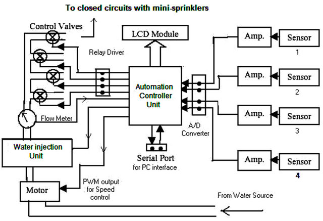
Figure 4. Controller unit.
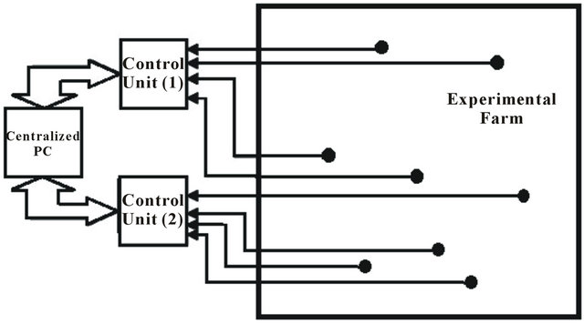
Figure 5. Application to field.
2.3. Using Simulation Program for Hydraulic Calculations
Hydro-Calc irrigation system planning software is designed to help the user to define the parameters of an irrigation system, Figure 6 Showing Hydro-Calc program. The user will be able to run the program with any suitable parameters, review the output, and change input data in order to match it to the appropriate irrigation system set up. Some parameters may be selected from a system list; whereas other are entered by the user according to their own needs so they do not conflict with the program’s limitations. The software package includes an opening main window, five calculation programs, one language setting window and a database that can be modified and updated by the user.
2.4. Hydro-Calc Includes Several Sub-Programs as Following
Figure 7 indicate that the Emitters program calculates the cumulative pressure loss, the average flow rate, the water flow velocity etc. in the selected emitter. It can be changed to suit the desired irrigation system parameters. The SubMain program calculates the cumulative pressure loss and the water flow velocity in the sub-main distributing water pipe (single or telescopic). It changes to suit the required irrigation system parameters. The Main Pipe program calculates the cumulative pressure loss and the water flow velocity in the main conducting water pipe (single or telescopic). It changes to suit the required irrigation system parameters. The Shape Wizard program helps transfer the required system parameters (Inlet Lateral Flow Rate, Minimum Head Pressure) from the Emitters program to the Sub-Main program. The Valves program calculates the valve friction loss according to the given parameters. The Shifts program calculates the irrigation rate and number of shifts needed according to the given parameters.
The Emitters program is the first application which can be used in the frame of Hydro-Calc software program. There are 4 basic type of emitters which can be used: Mini-sprinkler Line, On line, Sprinklers and Micro-
Figure 6. Hydro-calc irrigation planning.
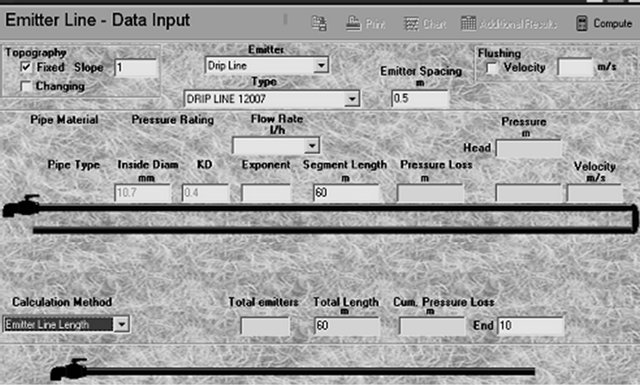
Figure 7. Hydro-calc working sheet before computation procedure.
Sprinklers. According to the previous selection the user can opt for a specific emitter which can be a pressure compensated or a non-pressure compensated. Each emitter has its own set of nominal flow rate values available. After the previous mentioned fields were completed, the program automatically fills the following fields: “Inside Diameter”, “KD” and “Exponent”, values which cannot be changes unless the change will be made in the database.
Figure 8 Showed that the steps of Flow chart for Hydro-Calc simulation program are components, planning, design, and calculating the hydraulic analysis of Minisprinkler irrigation system at different slopes or levels. The segment length is next field in which the user must introduce a value. The end pressure represents the actual value for calculation of pressure at the furthest emitter. There are some common values for this field: around 10 m for Mini-sprinkler, around 20 m for mini-sprinklers, between 20 - 30 m for sprinklers and around 2 m when using the flushing system. There are 2 more options which can be filled before starting the computation, options which can also be used with their default values. The Flushing field can be used if the user intends to calculate a system that includes and lateral flushing. Flushing option will work only in subsequently will be used the “Emitter Line Length” calculation method. The second option is about topography. Default value is 0%. Topography field has 2 sub-fields: fixed slope and changing slope. Usually the slopes values are not exceeding 10%. In many cases the slope is not uniform.
2.5. Validation of Measured Data with Calculated Data by Hdro-Calc
The emission rate for 10 emitters tested for each Lateral line for lengths (40, 60 and 80 m) at three stages. First, middle and end on the line were calculated theoretically using the following procedure (Figure 8). The head loss due to friction and insertion of emitters was calculated and then the pressure head at every emitter was determined. The emission from every emitter was calculated using the characteristic equation developed for pressure head vs. discharge for each product.
Costat program was used to carry out statistical analysis. Treatments mean were compared using the technique of analysis of variance (ANOVA) and the least significant difference (L.S.D) between systems at 1% had been done. The randomized complete block design according to [4].
3. Results and Discussions
3.1. Validation of Lateral Lines Hydraulic Analysis by Hydro-Calc Simulation Program When Lateral Lines Did Not Slope (0%) and Sloped down by (7%)
Validation of the Hydro-Calc Simulation Program
The discharge rates and pressures at the Mini-sprinkler head were measured under field conditions at three sites along the lateral lines (start, middle and end) for CM2MSIS, CM1M-SIS, and TDIS with lateral line length 60 m and for two different slopes of the Mini-sprinkler line (0 and 7%). Empirical measurements were used to validate the Mini-sprinkler simulation program (Hydro-Calc Simulation program copyright 2009 developed by NETAFIM, USA). Hydro-Calc, was a computer simulation Program used for planning and design of Mini-sprinkler or sprinkler irrigation systems. Modification of closed circuit Mini-sprinkler lateral lines irrigation depended on hydraulic equations such as, Hazen-William’s equations, Pernolli’s equations, etc. The data inputs provided to Hydro-Calc were shown in Table 1. The empirical data depended on the laboratory measurements of pressures and discharge, as well as the field uniformity.
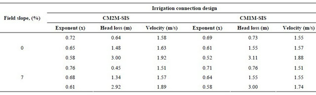
The predicted outputs of Hydro-calc simulation program (exponent (X), pressure head loss (m), velocity (m/s), and pressure along the lateral line Mini-sprinkler pers) were shown in Table 2 and Figures 9-12.
3.2. Predicted and Measured Head Loss Analysis along the Lateral Mini-Sprinkler Line of Closed Circuit Designs with No Slope 0%
The predicted head loss analysis along the lateral Mini-
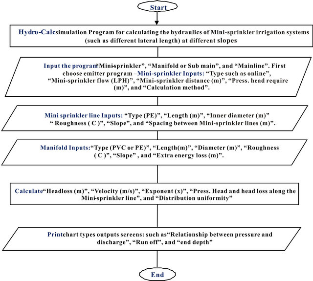
Figure 8. Flow chart components of hydro-calc simulation program for planning, design, and calculating the hydraulic analysis of mini-sprinkler irrigation system at different slopes or levels.
Table 1. Inputs for the hydro-calc simulation program for closed circuit designs Mini-sprinkler irrigation systems.
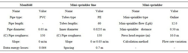
Table 2. Predicted exponent (x), head loss (m) and velocity (m/s) by the hydro-calc simulation program for closed circuits mini-sprinkler irrigation design with different slopes (0% and 7%).
sprinkler’s line had been calculated by Hydro-calc simulation program for closed circuits Mini-sprinkler irrigation systems CM2M-SIS and CM1M-SIS with no slope (0%) but with different lateral line length 60 m. Those predictions were tabulated in Table 3.
Table 3, Figures 9 and 10 showed the relationships among the predicted and measured head losses as well as the correlations Under CM2M-SIS and CM1M-SIS methods with no slope 0%. The irrigation methods could be ranked in the following ascending order CM1M-SIS < CM2M-SIS.
The correlation (Corr.) coefficients were obtained to compare the significant of the predicted and measured head loss along the lateral lines of the two closed circuits designs. Generally, the values of correlation analysis were (>0.90) when 0% field slope.
Data in Table 3 show the head pressures (bar) along the lateral lines of the different closed circuit designs CM2M-SIS and CM1M-SIS. Clearly the irrigation closed circuits designs under study could be ranked in the following ascending order CM1M-SIS
Table 3. Pressure head analysis along the lateral lines in mini-sprinkler irrigation closed circuits CM2M-SIS and CM1M-SIS methodswhen slope 0% level.
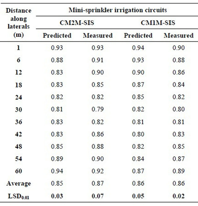
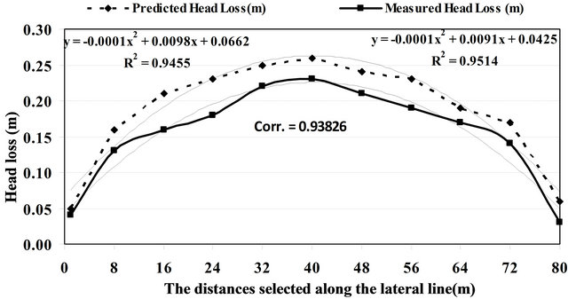
Figure 9. The relationship between different lateral line length 60 m and both the predicted and measured head losses when the slope was 0% with the CM2M-SIS design.
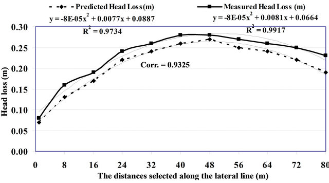
Figure 10. The relationship between different lateral line lengths (40, 60, 80 m) and both the predicted and measured head losses when the slope was 0% with the CM1M-SIS design.
differences between the all pressure head values of start, data are supported by [5-11].
3.3. Predicted and Measured Head Loss Analysis along the Lateral Mini-Sprinkler Line of Closed Circuits with a 7% Downward Slope from the Manifold to the Terminus
The predicted head loss analysiswhen lines sloped by 7% along the lateral Mini-sprinklers line had been calculated by Hydro-calc simulation program for closed circuits Mini-sprinkler irrigation systems CM2M-SIS and CM1MSIS. Figures 11 and 12 and Table 4 showed the relationship between predicted and measured head losses as well as the correlations. Irrigation methods under study when using lateral length 60 m could be ranked in the following ascending order according the values of the predicted and measured head losses CM1M-SIS < CM2M-SIS.
While by using Lateral length 80m the values of the predicted and measured head losses under irrigation methods could be ranked in the following ascending orders;CM2M-SIS < CM1M-SIS. This may be attributed to the different numbers of mini-sprinklers or how many mini-sprinklers were built-in with every lateral line
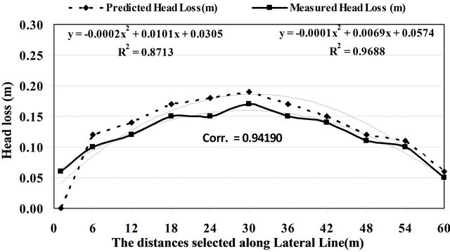
Figure 11. The relationship between different lateral line length 60 m and both the predicted and measured head loss when the line sloped 7% down with the CM2M-SIS design.
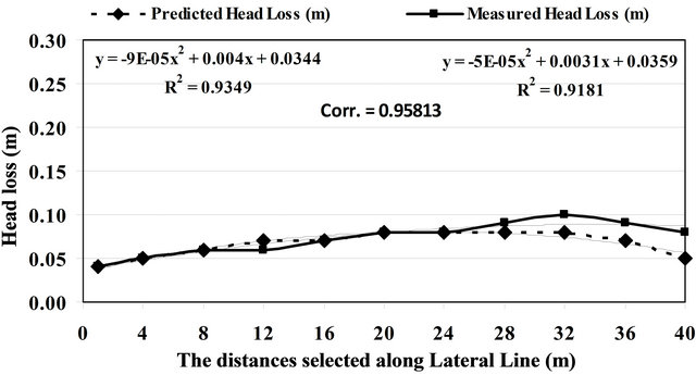
Figure 12. The relationship between different lateral line length 60 m and both the predicted and measured head loss when sloped 7% down with the CM1M-SIS design.
Table 4. Pressure head analysis along the lateral lines in Mini-sprinkler irrigation closed circuits CM2M-SIS and CM1M-SIS method when slope 7% level.

length.
The correlation (Corr.) coefficients were used to compare the predicted and measured head losses along thelateral lines of all the closed circuits designs. Generally, the values of correlation analysis were (>0.90) were obtained with 0% field slope 60 m length (experimental conditions) for all closed circuits.
Data in Table 4 and Figures 11 and 12 shows the head pressures(bar) along the lateral lines of the different closed circuit designs CM2M-SISand CM1M-SIS.When using lateral length 60 m under CM2M-SIS and CM1MSIS methods. According to Lateral length 60m the values of the pressure head under irrigation methods could be arranged in the following ascending orders CM1M-SIS < CM2M-SIS. This may be attributed to the decreased the head loss lateral line length by using the modified method CM2M-SIS and CM1M-SIS. LSD0.01 values in Table 4 show that Under CM2M-SIS and CM1M-SIS there is no significant difference between both start and end values of pressure head (bar) but there are significant differences between middle value and both start and end pressure head values. The interaction between irrigation methods: at the start there are significant differences between CM2M-SIS and CM1M-SIS. While at both of end and middle there are significant differences between all irrigation methods. These data are agreed well with the following references [5-12].
4. Conclusion
Automation controllerforclosed circuits of Minisprinkler irrigation system proves to be a real time feedback control system which monitors and controls all the activities of closed circuits of Mini-sprinkler irrigation system efficiently. The present proposal is a model to modernize the agriculture industries at a mass scale with optimum expenditure. Using this system, one can save manpower, water to improve production and ultimately profit. The data could be summarized in following: Irrigation methods under study when using lateral length 60 m could be ranked in the following ascending order according the values of the predicted and measured head losses CM1M-SIS < CM2M-SIS.The correlation (Corr.) coefficients were used to compare the predicted and measured head losses along the lateral lines of all the closed circuits designs. Generally, the values of correlation analysis were (>0.90) were obtained with 0% field slope 60m length (experimental conditions) for all closed circuits. The interaction between irrigation methods: at the start there are significant differences between CM2M-SIS and CM1M-SIS.
5. Acknowledgements
This paper is part of the mission of Dr. Hani Abdel-Ghani Abdel-Ghani Mansour to USA. So authors would to thanks WRFI Dept., Agricultural Division, National Research Center, Prof. Dr. David A. Lightfoot, PSAS Dept., SIUC, USA., and Ministries of Higher Education and Scientific Research in Egypt.
REFERENCES
- H. A. Mansour, “Design Considerations for Closed Circuits of Drip Irrigation System,” Ph.D. Thesis, Faculty of Agriculture, Ain Shams University, Cairo, 2012.
- H. A. Mansour, M. Y. Tayel, D. A. Lightfoot and A. M. El-Gindy, “Energy and Water Saving by Using Closed Circuits of Mini-Sprinkler Irrigation Systems,” Agriculture Science Journal, Vol. 1, No. 3, 2010, pp. 1-9. http://www.scirp.org/journal/as/
- P. Ashok and K. Ashok, “Microcontroller Based Drip Irrigation System,” 1st BTech, ECE, 2010. http://www.yuvaengineers.com/?p=583
- R. G. D. Steel and J. H. Torrie, “Principles and Procedures of Statistics, a Biometrical Approach,” 2nd Edition, McGraw Hill Inter. Book Co., Tokyo, 1980.
- H. A. Mansour and A. S. Aljughaiman, “Water and Fertilizers Use Efficiency of Corn Crop under Closed Circuits of Drip Irrigation System,” Journal of Applied Sciences Research, Vol. 8, No. 11, 2012, pp. 5485-5493.
- M. Y. Tayel, A. M. El-Gindy and H. A. Mansour, “Effect of Drip Irrigation Circuit Design and Lateral Line Lengths III—On Dripper and Lateral Discharge,” Journal of Applied Sciences Research, Vol. 8, No. 5, 2012, pp. 2725- 2731.
- M. Y. Tayel, A. M. El-Gindy and H. A. Mansour, “Effect of Drip Irrigation Circuit Design and Lateral Line Lengths IV—On Uniformity Coefficient and Coefficient of Variation,” Journal of Applied Sciences Research, Vol. 8, No. 5, 2012, pp. 2741-2748.
- M. Y. Tayel, H. A. Mansour and D. A. Lightfoot, “Effect of Drip Irrigation Circuit Design and Lateral Line Lengths I—On Pressure Head and Friction Loss,” Agriculture Science, Vol. 3, No. 3, 2012, pp. 392-399. http://www.scirp.org/journal/as
- M. Y. Tayel, H. A. Mansour and D. A. Lightfoot, “Effect of Drip Irrigation Circuit Design and Lateral Line Lengths II—On Flow Velocity and Velocity Head,” Agriculture Science, Vol. 3, No. 4, 2012, pp. 531-537. http://www.scirp.org/journal/as
- C. M. Burt, A. J. Clemens, T. S. Strelkoff, K. H. Solomon, R. D. Blesner, L. A. Hardy and T. A. Howell, “Irrigation Performance Measures: Efficiency and Uniformity,” Journal of Irrigation and Drainage Engineering, Vol. 123, No. 6, 1997, pp. 423-442. doi:10.1061/(ASCE)0733-9437(1997)123:6(423)
- N. Mizyed and E. G. Kruse, “Emitter Discharge Evaluation of Subsurface Trickle Irrigation Systems,” Transactions of the ASAE, Vol. 32, No. 4, 1989, pp. 1223-1228.
- A. G. Smajstrla and G. A. Clark, “Hydraulic Performance of Micro-Irrigation Mini-Sprinkler Tape Emitters,” ASAE Paper No. 92-2057, St Joseph, 1992. http://www.toromicro-irrigation.com
NOTES
*Corresponding author.