Journal of Minerals and Materials Characterization and Engineering
Vol.05 No.04(2017), Article ID:77165,13 pages
10.4236/jmmce.2017.54014
The Effect of Atmospheric Plasma Paint Stripping on the Fatigue Crack Growth Properties of Aluminium Substrates
Ali Merati, Marko Yanishevsky, Tessa Despinic, Philip Lo
National Research Council Canada, NRC Aerospace, Ottawa, Canada
![]()
Copyright © 2017 by authors and Scientific Research Publishing Inc.
This work is licensed under the Creative Commons Attribution International License (CC BY 4.0).
http://creativecommons.org/licenses/by/4.0/


Received: February 15, 2017; Accepted: June 23, 2017; Published: June 26, 2017
ABSTRACT
Paint removal is a common maintenance requirement for aircraft as well as naval and land vehicles, since external paint gets damaged and loses much of its corrosion protection effectiveness with time. Paint removal is also conducted when metallic aircraft structures are inspected periodically for fatigue cracks and corrosion. The conventional methods of removing paint employed throughout the Canadian Forces mainly include chemical stripping and abrasive media blasting. Chemical stripping involves the use of hazardous chemicals, which are high in Volatile Organic Compounds (VOC) and Hazardous Air Pollutants (HAP). Abrasive media blasting typically results in a substantial quantity of solid waste consisting of paint and blast residues. Such waste is subject to control under increasingly stringent environmental and safety regulations and its disposal is costly. The new Atmospheric Plasma (AP) paint removal process purports to be a high chemical energy, low thermal energy (cold plasma process), that should not damage temperature sensitive substructures, such as heat treated aerospace aluminium alloys. Fatigue strength is one of the key properties in aircraft structures. In order for AP paint stripping to be accepted as an aerospace industry standard paint removal process, it must be thoroughly tested to demonstrate that it does not adversely affect the fatigue properties of the substrate. This paper investigates effect of the paint removal process on fatigue crack growth of 7075-T6 and 2024-T3 aluminium panels.
Keywords:
Atmospheric Plasma, Paint Stripping, Fatigue Life, Topcoat, Primer, Non-Destructive Testing (NDT), Fatigue Cracks, Aerospace, Aluminium Alloys

1. Introduction
Fatigue is a localized damage process produced by cyclic loading, consisting of crack nucleation, propagation and final failure. The fatigue failure of a material is dependent on the interaction of a large stress with critical flaws or discon- tinuities. Since fatigue cracks almost always nucleate at a free surface, any surface condition and treatment can have significant effect on fatigue life. At low applied stresses or high cycle fatigue, the crack nucleation and early (short) crack growth period dominates the fatigue life and, therefore, factors such as surface finish and treatment become even more influential [1] [2] [3] [4] .
The presence of a clad/anodized layer and residual tensile stresses has proven to be the controlling factors for crack nucleation of aluminium alloys [4] . Therefore the exposure of the metal surface to plasma treatment could override, mask or add to the deleterious effect of the current surface condition.
Investigation of failure modes in aircraft structures suggests that 62% of significant failures can be attributable to fatigue, while only 14% due to overload [5] . The importance of fatigue in aerospace structural design suggests the need for addressing the effect of the novel de-painting method on fatigue behaviour.
It should be noted that certain materials have a fatigue limit or endurance limit, which represents a stress level below which the material will not fail and can be cycled indefinitely. Unlike steel and titanium (in benign environmental conditions), aluminium, as many other alloys, does not exhibit well defined endurance limits (see Figure 1). In other words, they will fail eventually; it is only a matter of accumulating a sufficient number of cycles over their lifetime [6] [7] .
During the normal lifespan of a military aircraft, many cycles of de-painting and re-painting processes are performed to prevent corrosion or any surface deterioration and to enable necessary inspections for cracks and other surface damages. It is imperative to determine the effects of any potential paint stripping method on mechanical properties, in particular, the fatigue behaviour of substrate
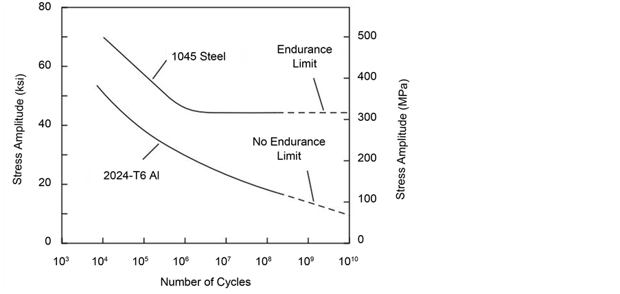
Figure 1. S-N curve of aluminium and steel alloys [6] [7] .
materials. In addition, aluminium alloys such as 7075-T6 or 2024-T3 gain their high strength due to their specific heat treatment. Consequently, the paint stripping process should not negatively affect the mechanical properties of the alloy. Atmospheric Plasma paint stripping is a non-intrusive, media-free process for removing organic coatings from a variety of substrates and has the potential to replace conventional paint stripping methods. The power supply in the Atmospheric Plasma process produces a high frequency electromagnetic field. As compressed air flows across the field, the atoms become ionized and produce “cold” plasma [8] . The chemical energy oxidizes the organic component found in paints and coatings, converting much of the removed paint into harmless gases such as water vapour, CO2, and solid residue. The total solid waste volume is estimated to be about only 10% of the original paint coating volume.
2. Materials & Procedure
Aluminium 7075-T6 and 2024-T3 are common alloys used in the aerospace industry, which are made with a specific temper (heat-treatment). Four test panels prepared of the two alloys in two thicknesses were used to investigate the effects of Atmospheric Plasma paint stripping on the materials’ properties, in particular fatigue. All the test panels had dimensions of 16'' × 48'' with a total number of 112 holes of approximately 0.125'' (3.175 mm) in diameter featuring 0.015'' Electron Discharge Machining (EDM) notches. Due to preferential fatigue cracking occurring in the outer holes on the panel, the 34 holes with EDM notches were machined out and cold expanded using Fatigue Technology Inc. (FTI) CBTS 4-4-N-1A1.1860 tooling, leaving 78 holes with EDM notches, as shown in Figure 2. The panels were then sent to the Canadian Quality Engineering Test Establishment (QETE) for surface preparation and priming/painting which included Alodine 1201 (pre-treatment meeting MIL-DTL-5541 Ty I Cl 1A) and coating with primer (MIL-PRF-23377 Ty I Cl C2) and finishing with grey blue top coat (MIL-PRF-85285 Ty I Cl H FED-STD-595C #35237). The primer was composed of additional anti-corrosion pigments and normally dried with a slightly rough surface to enhance adhesion ability to the topcoat [9] [10] . The topcoat was de-

Figure 2. Test panel prior to Atmospheric Plasma paint stripping illustrating the hole setup with dotted lines and arrows. The inset shows the close up of a hole with an EDM notch.
signed to adhere to the primer and create a smooth, outer protective layer whose colour depended on the pigments used.
The Atmospheric Plasma paint stripping was performed using a PlasmaFlux system manufactured by Atmospheric Plasma Solutions (APS) [11] [12] [13] , shown in Figure 3(a).
The process was performed in a working chamber with a 3D robotic surface equipped with an exhaust and filtration system. The plasma generated a high velocity flow of chemically active nitrogen and oxygen radicals, which exited the nozzle tip as a plasma plume, as shown in Figure 3(b). The robotic stage and plasma pen were controlled by three stepper motors and three rack and pinion drives that have the ability to move in the X (forward), Y (side), and Z (height) directions.
After partially stripping the aluminium panels, an MTS Uniaxial Load Frame was used to cyclically load the panels, as shown in Figure 4. Each panel was fatigue loaded using a sinusoidal waveform at a gross maximum stress of 14 ksi, load ratio R = 0.1, and a frequency of 3 Hz. The testing parameters and the resulting number of cycles to produce similar size cracks from all the holes are listed in Table 1. Fatigue cycling was concluded after each panel showed sufficiently large cracks, as shown in Figure 6.
The panels were then scanned using a TecScan Eddy Current (EC) Scanner to map out cracks emanating from each hole. A typical EC scan is shown in Figure 5.
To determine whether the test panels had been locally altered due to heat from the AP process, conductivity tests were performed on all panels in accordance to ASTM E1004-09 [14] before and after the paint removal treatments.
To investigate the effect of stripping process on fatigue crack growth, specific rows on each panel were selected and exposed to Atmospheric Plasma paint stripping with the parameters described in the following section. The rows were selected due to their location on the test panel and their ability to be compared to equivalent rows (lines) on the test panel.
 (a)
(a) (b)
(b)
Figure 3. Front view of APS PlasmaFlux paint removal system with: a) 3D robot and exhaust cabinet; and b) close up of the plasma plume.

Figure 4. A test panel mounted in a MTS uniaxial load frame for fatigue testing.

Figure 5. Fatigue tested panels scanned by EC showing the fatigue cracks developed from all notched holes (Al 7075-T6 TP2 Thick).

Table 1. Parameters of fatigue testing aluminium panels.
3. Results & Discussion
This study investigated whether Atmospheric Plasma paint removal would affect crack growth by fatigue testing 7075-T6 and 2024-T3 aluminium panels after paint stripping and analyzing the results through Non-Destructive Evaluation (NDE) techniques. The results are discussed in two subheadings of paint removal and fatigue testing to demonstrate the effect of removal process (if any) on the fatigue behaviour of the substrate metals.
3.1. Paint Stripping
Four aluminium panels were paint stripped along specific rows, as shown in Figure 6. The stripped lines were compared to the similar locations on the opposite end of the panel, in terms of fatigue crack growth behaviour. The test panel was designed in order to subject the notched holes to the same tensile fatigue loads. This enables the comparison between fatigue results of symmetrical holes, and sheds light on the effect of de-painting process, if any. Aluminium panels “Al 7075-T6 TP6 Thick” and “Al 2024-T3 TP3 Thin” were stripped in three regions while “Al 7075-T6 TP5 Thick” and “Al 2024-T3 TP2 Thin” were stripped in two regions.
Different severities of the AP paint stripping process were performed on each row of the panel, in terms of the thickness of paint left on the panel, as shown in Table 2. Figure 7 shows two typical cross sections of pristine and stripped
 (a)
(a) (b)
(b)
Figure 6. Panel layout showing the types of stripped panels: a) stripped in three regions (lines) of panel Al 2024-T3 TP3 Thick; and b) stripped in two lines of panel Al 7075-T6 TP5 Thick.
![]() (a)
(a)![]() (b)
(b)
Figure 7. Metallographic cross section of the test panel Al-2024-T3 TP2 Thin: a) illustrating unstripped region of primer (yellow-green)and topcoat (grey); and b) stripped region with approximately half of remaining primer thickness.
regions of the 2024-T3 TP2 Thin test panel. Depending on the panel, the average primer thickness ranged from 13 to 32 µm and the total paint plus primer thickness ranged from 40 to 70 µm.
3.2. Fatigue Testing
Following paint stripping, the panels were then subjected to cyclic loading to generate cracks emanating from EDM notches at the panel holes. The resultant crack lengths of stripped and unstripped lines were measured and compared. Figure 8 is an example of the TecScan Eddy Current scanner used to obtain an accurate image of the test panels; the associated software was used to measure
Table 2. Paint stripping parameters and remaining paint thicknesses of the paint stripped lines for each aluminium panel.
*Measurements were averaged from 8 data points.
![]()
Figure 8. Resulting EC scan showing test panels with cracks (Al-7075-T6 TP3), with crack measurements.
each crack length individually. The typical measurements are provided in Table 3 showing a comparison of cracks from stripped areas to their counterparts which had not been stripped. Figure 10 shows the crack length results for each hole
Table 3. Al 2024-T3 TP3 Thin panel crack length measurements and averages, units are in inches.
*Stripped Lines.
in the test panel along specific lines. As can be seen by the red lines, the fatigue cracks in the paint stripped holes were rarely larger than those in the non- stripped holes. The graph could even imply that the stripped holes are in fact slightly shorter than the non-stripped holes as they seem to rest in the bottom of the pack of lines.
The results are summarized as graphs in Figures 9-12 which provide the average crack length for each stripped and unstripped line. Considering the results, the range of crack lengths for both stripped and unstripped regions appear to be very similar; indicating that the AP paint removal process did not appear to negatively affect the fatigue crack growth behaviour on any of the panels.
It should be noted that the plasma paint stripping process requires several passes to be conducted over the same painted area, and the substrate became hot for several minutes depending on the de-painted surface area. However, the extent of heat and its duration did not seem to be sufficient to alter the heat treatment of the aluminium alloys and consequently their fatigue properties. It should also be noted that conductivity testing after paint stripping did not reveal any change of temper in any of the four panels as shown in Table 4 [15] [16] .
It is noteworthy that though the maximum and minimum loads were kept the same, the cracks on the aluminium 7075-T6 panels were generated in significantly fewer cycles than the cracks on the aluminium 2024-T3 panels. For example, the Al-2024-T3 TP3 Thick panel required 18 hours in the MTS load frame but still generated shorter cracks than the Al-7075-T6 TP5 Thick panel that was fatigued for 8 hours. Al-2024-T3 is known to have superior fatigue properties to Al-7075-T6.
4. Concluding Remarks
The objective of this study was to determine whether paint stripping using Atmospheric Plasma was beneficial, detrimental or neutral to the fatigue crack growth properties of aluminium substrates.
Aluminium 2024-T3 and 7075-T6 panels were prepared with 78 holes with
![]()
Figure 9. Al-7075-T6 TP3 full crack length results and comparison between all lines on the test panel. The measurements in stripped regions are shown in orange colour.
![]()
Figure 10. Al-7075-T6 TP5 full crack length results and comparison between all lines on the test panel. The measurements in stripped regions are shown in orange colour.
![]()
Figure 11. Al-2024-T3 TP2 full crack length results and comparison between all lines on the test panel. The measurements in stripped regions are shown in orange colour.
![]()
Figure 12. Al-2024-T3 TP3 full crack length results and comparison between all lines on the test panel. The measurements in stripped regions are shown in orange colour.
Table 4. Conductivity measurements before and after AP paint stripping.
Note: Measurements were averaged from 8 measurements.
EDM notches to develop crack growth. The Panels were painted with a standard military aerospace primer and topcoat scheme to replicate the Canadian Forces in-service experience. An Atmospheric Plasma paint stripping process was used to de-paint specific regions of the panels for comparison to the non-stripped regions. Due to the presence of high temperatures during AP paint stripping, it was unknown whether the process would induce changes in the material property (temper) conditions of the aluminium panels. By varying the nozzle height, speed and number of passes, results were obtained for numerous severities of paint removal. The panels were then cyclically loaded in a load frame to generate visible cracks on the surface of the aluminium panels. The crack lengths on both the paint-stripped and unstripped regions were measured and compared.
Conductivity measurements indicated no change in conductivity to any portion of the test panels; including the most severely paint stripped locations. This observation demonstrates that the duration of local heat exposure from the plasma torch appeared to not be long enough to change the precipitation condition (temper) of the alloys. Plotting the results of the crack length measurements revealed that the AP paint stripping process was neither detrimental nor beneficial to the fatigue crack growth properties of the metallic substrates. In all cases, regardless of paint colour, substrate thickness or aluminium alloy, the averages of the crack lengths in the paint stripped regions were approximately equivalent to the lengths in the unstripped regions.
In summary, the results in this study are encouraging for the Atmospheric Plasma paint stripping process and support further development for the technology’s emergence into industrial applications for paint stripping.
Acknowledgements
We appreciate the efforts and assistance of volunteer students Ocdts A. Abdelhamed, S. Savard, J. Lapointe from the Royal Military College and D. Sharma from Carleton University with the experimental work, gathering data and documenting this report. The present work was performed as a contribution to the DND/DRDC funded project Al-004516.
Cite this paper
Merati, A., Yanishevsky, M., Despinic, T. and Lo, P. (2017) The Effect of Atmospheric Plasma Paint Stripping on the Fatigue Crack Growth Properties of Aluminium Substrates. Journal of Minerals and Materials Characterization and Engineering, 5, 161-173. https://doi.org/10.4236/jmmce.2017.54014
References
- 1. Laz, P.J. and Hillberry, B.M. (1998) Fatigue Life Prediction from Inclusion Initiated Cracks. International Journal of Fatigue, 20, 263-270.
- 2. Halliday, M.D., Cooper, C., Poole, P. and Bowen, P. (2003) On Predicting Small Fatigue Crack Growth and Fatigue Life from Long Crack Data in 2024 Aluminum Alloy. International Journal of Fatigue, 25, 709-718.
https://doi.org/10.1016/S0142-1123(03)00052-5 - 3. Newman, J.C. and Edwards, P.R. (1988) Short-Crack Growth Behaviour in an Aluminum Alloy—An AGARD Cooperative Test Programme. NATO, Advisory Group for Aerospace Research and Development, Neuilly sur Seine, France.
- 4. Merati, A., Tsang, J. and Eastaugh, G. (2003) Final Report—Test Results for the Determination of Fatigue-Related Features of the Initial Discontinuity State (IDS) of 2024-T3 Aluminium Alloys. NRC/IAR Report, LTR-SMPL-2003-0001.
- 5. Findlay, S.J. and Harrison, N.D. (2002) Why Aircraft Fail. Materials Today, 5, 18- 25.
https://doi.org/10.1016/S1369-7021(02)01138-0 - 6. Kalpakjian, S. (1995) Manufacturing Engineering and Technology. 3rd Edition, Addison-Wesley Publishing Co., Boston.
- 7. ASM International (2008) Elements of Metallurgy and Engineering Alloys. Metals Handbook, Chapter 14: Fatigue, p. 246.
- 8. Yancey, P. (2012) Atmospheric Plasma De-Painting. Atmospheric Plasma Solutions Inc., Cary, NC.
- 9. Henkel (2016) Henkel Adhesives North America.
http://na.henkel-adhesives.com/product-search-1554.htm?nodeid=8797999529985 - 10. Resene (2009) Primers, Sealers and Undercoats. NZIA/DBH-Resene CPD, February.
http://www.resene.co.nz/archspec/cpd_earn_points/pdfs/CPD_primerssealersandundercoats.pdf - 11. Yanishevsky, M. and Pankov, V. (2015) NRC Operating Procedure for APS PlasmaFlux Paint Removal System—LTR-SMPL-2015-0144. NRC, Ottawa.
- 12. Merati, A., Yanishevsky, M., Despinic, T. and Lo, P. (2016) Metallographic Analysis of Paint Stripping Techniques—Atmospheric Plasma—LTR-SMM-2016-0015. NRC, Ottawa.
- 13. Merati, A., Yanishevsky, M., Despinic, T. and Lo, P. (2016) Atmospheric Plasma—An Alternative Paint Stripping Process for Aircraft Structures. NRC, Ottawa.
- 14. ASTM E1004-09 Standard Test Method for Determining Electrical Conductivity Using the Electromagnetic (Eddy-Current) Method. 2009.
- 15. Merati, A., Lo, P., Despinic, T., Yanishevsky, M. and Genest, M. (2016) Effect of Paint Removal Techniques on Crack Detectability—Liquid Penetrant Inspection—LTR-SMM-2016-0062. NRC, Ottawa.
- 16. Merati, A., Lo, P., Despinic, T., Yanishevsky, M. and Genest, M. (2016) Effect of Paint Removal Process on Crack Detectability Using Liquid Penetration Inspection Method. NRC, Ottawa.