International Journal of Medical Physics, Clinical Engineering and Radiation Oncology
Vol.3 No.2(2014), Article ID:45720,6 pages DOI:10.4236/ijmpcero.2014.32013
Predicting Delivery Error Using a DICOM-RT Plan for Volumetric Modulated Arc Therapy
Hideharu Miura1*, Masao Tanooka2, Masayuki Fujiwara1, Yasuhiro Takada1, Hiroshi Doi1, Soichi Odawara1, Kengo Kosaka1, Norihiko Kamikonya1, Shozo Hirota1
1Department of Radiology, Hyogo College of Medicine, 1-1, Mukogawa-cho, Nishinomiya City, Hyogo, Japan
2Department of Radiological Technology, Hyogo College of Medicine College Hospital, Hyogo, Mukogawa-cho, Nishinomiya City, Hyogo, Japan
Email: *hide-miura@osaka-igrt.or.jp
Copyright © 2014 by authors and Scientific Research Publishing Inc.
This work is licensed under the Creative Commons Attribution International License (CC BY).
http://creativecommons.org/licenses/by/4.0/


Received 1 February 2014; revised 1 March 2014; accepted 21 March 2014
ABSTRACT
The purpose of this study was to investigate the prediction of mechanical error using DICOM-RT plan parameters for volumetric modulated arc therapy (VMAT). We created plans for gantry rotation arcs of 360° and 180° (full-arc and half-arc VMAT) for six maxillary sinus cancer cases using a Monaco treatment planning system, and delivered the doses with a linear accelerator. We calculated DICOM-RT plan parameters, including gantry, multileaf collimator (MLC) positions and Monitor Units (MU). We compared plans with regard to gantry angle per MU (degrees/MU) and MLC travel per MU (mm/MU) for each segment. Calculated gantry angle/MLC position speeds and errors were evaluated by comparison with the log file. On average, the half-arc VMAT plan resulted in 47% and 35% fewer degrees/MU and mm/MU than the full-arc VMAT plan, respectively. The root mean square (r.m.s.) gantry and MLC speeds showed a linear relationship with calculated degrees/MU and mm/MU, with coefficients of determination (R2) of 0.86 and 0.72, respectively. The r.m.s. gantry angle and MLC position errors showed a linear relationship with calculated degrees/MU and mm/MU with R2 of 0.63 and 0.76, respectively. Deviations from plan parameterswere related to mechanical error for VMAT, and provided quantitative information without the need for VMAT delivery. These parameters can be used in the selection of treatment planning.
Keywords:Volumetric-Modulated Arc Therapy, DICOM-RT Plan, Patient-Specific QA, Radiotherapy Planning, Computer-Assisted

1. Introduction
Volumetric-modulated arc therapy (VMAT) is the administration of intensity-modulated radiotherapy (IMRT) in a single gantry arc, in which gantry speed, dose rate, and multileaf collimator (MLC) leaf speed are varied during gantry rotation [1] . VMAT is comparable to IMRT, but features decreased delivery time and lower monitor units (MU) [2] . This delivery technique demands a more complex treatment delivery scheme, requiring patientspecific quality assurance (QA). Pretreatment patient-specific QA methods described to date include film and ion chambers in a cylindrical water phantom [3] and a 2-dimensional array of ion chambers [4] . Newer phantoms have been developed for VMAT include the Delta4 (Scandidos, Uppsala, Sweden) [5] and ArcCHECK (Sun Nuclear Corp., Melbourne FL, USA) [6] , as well as electronic portal imaging devices (EPID) [7] that can replace film measurement. However, these devices cannot evaluate plan parameters such as gantry or MLC position.
Several groups have proposed the use of machine log file analysis as an alternative for IMRT and VMAT QA [8] -[10] . However, log file evaluation must be performed after VMAT delivery. Neelan et al. developed a real time dose monitoring tool and reported that the linac data monitor is capable of detecting and quantifying mechanical and dosimetric errors at various stages of planning and delivery [10] . The accuracy of a given plan depends on the plan’s characteristics. We speculated that machine parameters from DICOM-RT plan may be used to predict mechanical errors in gantry angle and MLC position.
We investigated the prediction of mechanical error when using DICOM-RT VMAT plan parameters, assessing delivery by recording gantry angle and MLC position errors during VMAT delivery in a log file.
2. Materials and Methods
2.1. Treatment Planning
Six patients with maxillary sinus cancer were randomly selected for the study. VMAT plans were created using the Monaco 3.0 (Elekta, Maryland Heights Missouri, USA) treatment planning system (TPS). We compared gantry rotation angles of 360˚ (full-arc VMAT) and 180˚ (half-arc VMAT). In our previous study, root mean square (r.m.s.) gantry acceleration and r.m.s. gantry angle error during half-arc VMAT delivery were 30% and 23% lower than those during full-arc VMAT delivery, respectively [11] . We defined gross tumor volume (GTV) as visible tumor on computed tomography (CT) and magnetic resonance imaging (MRI). We defined the clinical target volume (CTV) by adding an isotropic margin of 5 mm to the GTV. We defined the planning target volume (PTV) by adding an isotropic margin of 3 mm to the CTV to account for setup uncertainty and mechanical inaccuracy. The range of PTVs was 130.0 - 345.0 cc. We contoured the brain, brainstem, spinal cord, optic chiasm, ipsilateral and contralateral eyes, and ipsilateral and contralateral optic nerves as organs at risk (OARs). We fixed the collimator and couch angles at 0˚. We prescribed a dose of 66 Gy in 33 fractions to 95% of the PTV, and restricted the maximum dose to 110% of the prescribed dose. The dose-volume criteria used for the VMAT optimization can be found in our previous work [11] . We optimized the full-arc and half-arc VMAT plans with the same optimization objectives. Monaco TPS implement a two-stage process for the optimization of dose distributions. In the first stage, the fluence distribution of VMAT beams is optimized. In the second stage, the beam segmentation is optimized. A finite size pencil beam algorithm [12] is used for beamlet fluence optimization and fast calculation of dose from segmented beams. To provide more accurate dose calculations in the second stage, Monaco TPS also offers a Monte Carlo dose calculation engine based on the XVMC [13] code coupled with the virtual energy fluence model of a treatment head [14] . The Monaco TPS provides Monte Carlo dose calculations with a grid size of 3 mm and variance of 3%.
2.2. Calculation of Plan Parameters
We calculated parallel plan parameters using MATLAB (MathWorks Inc., Natick MA, USA) software, defining the specified gantry angle position, MLC leaf position, and cumulative delivered monitor units (MUs) for each segment. We calculated the gantry angle position, MLC positions, and MUs with a DICOM-RT plan, which determines gantry angle and MLC positions, and calculates the gantry and MLC parameters for each segment. We defined the gantry parameters from differences in position between gantry angle positions for each segment (degrees/MU). We defined MLC parameters using the number of MU at different positions of adjacent MLC leaves for each segment (mm/MU).
2.3. Plan Analysis
We used a 6 MV photon beam with an MLC leaf width of 10 mm for VMAT delivery with a Synergy linear accelerator (Elekta, Crawley, UK). We transferred treatment plans from the Monaco TPS to a Desktop Pro 7.01 linac controller via a Mosaiq ver 1.6 (Elekta, Sunnyvale California, USA) record and verify system. We evaluated gantry angle and MLC position errors using a log file that recorded cumulative MU as well as planned and actual gantry angles/MLC position every 250 milliseconds. We calculated gantry angle position error by subtracting the planned gantry angle position from the actual gantry angle position for each treatment time, and the MLC position error by subtracting the planned MLC position from the actual MLC position for each treatment time. We displayed the analyzed data as mean ± standard deviation with ranges in parentheses among the six clinical plans.
3. Results
Figure 1 shows representative histograms of plan parameters for full-and half-arc VMAT plans for the same patient. The gantry and MLC plan parameters for all patients were 1.07 ± 0.20 and 0.56 ± 0.11 degrees/MU versus 2.96 ± 0.83 and 1.92 ± 0.20 mm/MU for full-and half-arc VMAT, respectively. On average, the half-arc VMAT plan resulted in 47% and 35% fewer degrees/MU and mm/MU than the full-arc VMAT plan.
Figure 2(a) shows plots of (r.m.s.) gantry speed as a function of calculating the average degrees/MU, while Figure 2(b) shows plots of r.m.s. MLC speed as a function of calculating the average mm/MU for the fulland half-arc VMAT plans. The r.m.s gantry angle and MLC speeds for all patients were 0.42 ± 0.30 and 0.32 ± 0.03 degrees/second versus 0.50 ± 0.02 and 0.44 ± 0.02 mm/second for full-and half-arc VMAT plans, respectively. The r.m.s. gantry speeds showed a linear relationship with DICOM-calculated degrees/MU, with a coefficient of determination (R2) of 0.86. The r.m.s. MLC speed also showed a linear relationship with mm/MU with an R2 value of 0.72.
Figure 3(a) shows plots of r.m.s. gantry angle errors as a function of calculating the average degrees/MU,
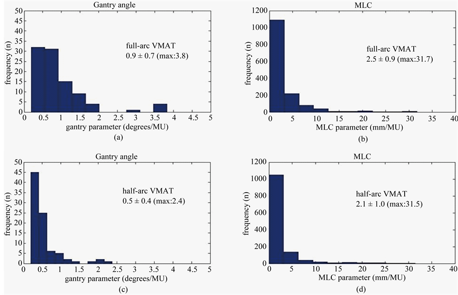
Figure 1. Histograms at (a) degrees/MU and (b) mm/MU for full-arc VMAT or (c) degrees/MU and (d) mm/MU for half-arc VMAT. On average, the degrees/MU and mm/MU of full-arc VMAT are larger than the half-arc VMAT.
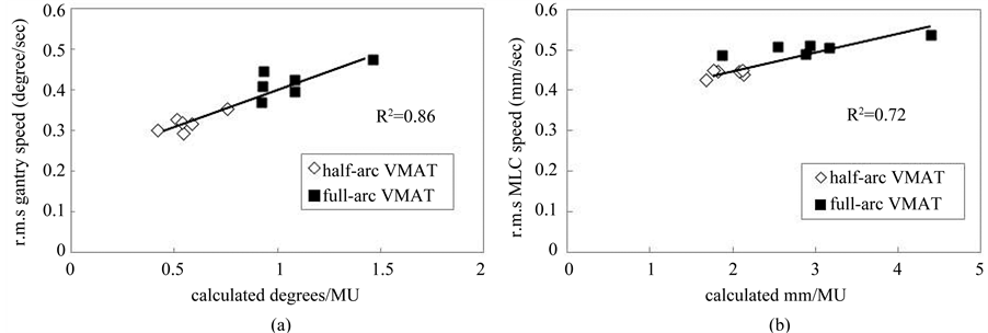
Figure 2. Relationship between full-arc (black square) and half-arc (white diamond) VMAT deliveries. (a) r.m.s. gantry speed as a function of gantry angle divided by MU for each segment (degrees/MU) and (b) r.m.s. MLC speed as a function of MLC travel distance divided by MU for each segment (mm/MU).
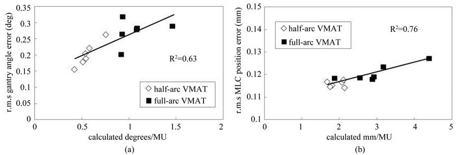
Figure 3. Relationship between full-arc (black square) and half-arc (white diamond) VMAT deliveries. (a) r.m.s. gantry angle error as a function of gantry speed divided by MU for each segment (degrees/MU) and (b) r.m.s. MLC error as a function of MLC travel distance divided by MU for each segment (mm/MU).
whereas Figure 3(b) shows plots of r.m.s. MLC position error as a function of calculating the average mm/MU for full-and half-arc VMAT plans. The r.m.s gantry angle and MLC position errors for all patients were 0.27 ± 0.04 and 0.20 ± 0.04 deg versus 0.12 ± 0.01 and 0.11 ± 0.01 mm for fulland half-arc VMAT plans, respectively. The r.m.s. gantry angle errors showed a linear relationship with DICOM-calculated degrees/MU with an R2 of 0.63. The r.m.s. MLC position error showed a linear relationship with DICOM-calculated mm/MU with an R2 value of 0.76.
4. Discussions
In this study, we investigated the relationship of DICOM-RT plan parameters with mechanical errors in VMAT plan. The r.m.s. degrees/MU and mm/MU in half-arc VMAT deliveries were smaller than those in full-arc VMAT deliveries. The larger gantry angle error might be explained by the greater acceleration of the gantry and accompanying greater inertia. Additionally, half-arc VMAT planning provided OAR sparing with identical homogeneity for the PTV [11] . On average, the half-arc VMAT resulted in 47% and 35% fewer degrees/MU and mm/MU than the full-arc plans. Plots of r.m.s. gantry angle position and MLC position errors versus calculated degrees/MU and mm/MU during the full-arc and half-arc VMAT deliveries showed an approximately linear correlation. Plan parameters with greater degrees/MU and mm/MU significantly increased gantry angle position and MLC position errors. These results suggest that quantitative analysis can predict mechanical errors in treatment planning. Larger standard deviations in gantry angle position error have been reported to strongly correlate with larger standard deviations in MLC position errors [15] . Therefore, fewer degrees/MU and mm/MU appear to improve the treatment plan. Leaf motion constraints can dramatically impact VMAT plan quality, dose calculation, delivery accuracy, and delivery efficiency. The discrepancy between planned and actual position errors may affect the dose distribution. Leaf travel can be controlled in most treatment planning systems using leaf-motion constraints [16] .
Several methods for assessing IMRT plan complexity have been proposed and extensively studied [17] -[19] . Webb introduced the modulation index (MI) with the intent of defining the degree of complexity of fluence maps [17] . McNiven et al. defined the modulation complexity score (MCS), a normalized sum over all segments of the aperture area variability (AAV) and leaf sequence variability (LSV) for a step-and-shoot IMRT static beam [19] . A high degree of complexity for fixed-beam IMRT has been associated with multiple parameters. Masiet et al. evaluated the effect of VMAT plan parameters and dosimetric accuracy, together with the possibility of scoring plan complexity [20] . They delivered the planned dose to a Delta 4 phantom for dosimetric verification. The complexity of VMAT plan optimization is mainly attributable to the need to account for the motion of the gantry and MLC during rotation. A finer control point separation led to a significant increase in dosimetric accuracy for plans with high MLC travel values, and to a decrease in correlation between leaf travel and passing rates [16] .
VMAT is associated with an increase in complexity that affects many steps of the treatment process, including treatment planning, QA workload, and treatment delivery itself. This additional complexity also extends to shapes, sizes, and relative locations of tumor and OARs, required tumor dose, dose homogeneity, and dose-volume limits of OARs. The treatment plan may need to be modified to minimize dosimetric error. Plan parameters may be an acceptable way of assuring the delivery of the VMAT plan. Information in DICOM-RT can be used for VMAT routine and plan-specific QA. Quantitative analysis may offer advantages for standardization of treatment planning across multiple institutions. Further study is needed to verify whether it is also useful for other treatment sites other than the maxillary sinus cancer.
5. Conclusion
In conclusion, we found that degrees/MU and mm/MU showed excellent value in predicting VMAT delivery accuracy. DICOM-RT plan parameters predicted mechanical error in VMAT plan, and provided quantitative information without necessitating VMAT delivery.
References
- Otto, K. (2008) Volumetric Modulated Arc Therapy: IMRT in a Single Gantry Arc. Medical Physics, 35, 310-317. http://dx.doi.org/10.1118/1.2818738
- Pasler, M., Wirtz, H. and Lutterbach, J. (2011) Impact of Gantry Rotation Time on Plan Quality and Dosimetric Verification-Volumetric Modulated Arc Therapy (VMAT) vs. Intensity Modulated Radiotherapy (IMRT). Strahlenther Onkol, 187, 812-819. http://dx.doi.org/10.1007/s00066-011-2263-1
- Masi, L., Casamassima, F., Doro, R. and Francescon, P. (2011) Quality Assurance of Volumetric Modulated Arc Therapy: Evaluation and Comparison of Different Dosimetric Systems. Medical Physics, 38, 612-621. http://dx.doi.org/10.1118/1.3533900
- Gloi, A.M., Buchana, R.E., Zuge, C.L. and Goettler, A.M. (2011) Rapid Arc Quality Assurance through Map Check. Journal of Applied Clinical Medical Physics, 12, 3251.
- Létourneau, D., Publicover, J., Kozelka, J., Moseley, D.J. and Jaffray, D.A. (2009) Novel Dosimetric Phantom for Quality Assurance of Volumetric Modulated Arc Therapy. Medical Physics, 36, 1813-1821. http://dx.doi.org/10.1118/1.3117563
- Korreman, S., Medin, J. and Kjaer-Kristoffersen, F. (2009) Dosimetric Verification of Rapid Arc Treatment Delivery. Acta Oncology, 48, 185-191. http://dx.doi.org/10.1080/02841860802287116
- Rowshanfarzad, P., Sabet, M., Barnes, M.P., O’Connor, D.J. and Greer, P.B. (2012) EPID-Based Verification of the MLC Performance for Dynamic IMRT and VMAT. Medical Physics, 39, 6192-6207. http://dx.doi.org/10.1118/1.4752207
- Sun, B., Rangaraj, D., Boddu, S., et al. (2012) Evaluation of the Efficiency and Effectiveness of Independent Dose Calculation Followed by Machine Log File Analysis against Conventional Measurement Based IMRT QA. Journal of Applied Clinical Medical Physics, 13, 3837.
- Litzenberg, D.W., Moran, J.M. and Fraass, B.A. (2002) Verification of Dynamic and Segmental IMRT Delivery by Dynamic Log File Analysis. Journal of Applied Clinical Medical Physics, 3, 63-72. http://dx.doi.org/10.1120/1.1449362
- Tyagi, N., Yang, K., Gersten, D. and Yan, D. (2012) A Real Time Dose Monitoring and Dose Reconstruction Tool for Patient Specific VMAT QA and Delivery. Medical Physics, 39, 7194-7204. http://dx.doi.org/10.1118/1.4764482
- Miura, H., Fujiwara, M., Tanooka, M., et al. (2012) Dosimetric and Delivery Characterizations of Full-Arc and Half- Arc Volumetric-Modulated Arc Therapy for Maxillary Cancer. Journal of Radiation Research, 53, 785-790. http://dx.doi.org/10.1093/jrr/rrs031
- Jeleń, U. and Alber, M. (2007) A Finite Size Pencil Beam Algorithm for IMRT Dose Optimization: Density Corrections. Physics in Medicine and Biology, 52, 617-633. http://dx.doi.org/10.1088/0031-9155/52/3/006
- Fippel, M. (1999) Fast Monte Carlo Dose Calculation for Photon Beams Based on the VMC Electron Algorithm. Medical Physics, 26, 1466-1475. http://dx.doi.org/10.1118/1.598676
- Fippel, M., Haryanto, F., Dohm, O., Nüsslin, F. and Kriesen, S. (2003) A Virtual Photon Energy Fluence Model for Monte Carlo Dose Calculation. Medical Physics, 30, 301-311. http://dx.doi.org/10.1118/1.1543152
- Haga, A., Nakagawa, K., Shiraishi, K., et al. (2009) Quality Assurance of Volumetric Modulated Arc Therapy Using Elekta Synergy. Acta Oncology, 8, 1193-1197. http://dx.doi.org/10.3109/02841860903081905
- Chen, F., Rao, M., Ye, J.S., Shepard, D.M. and Cao, D. (2011) Impact of Leaf Motion Constraints on IMAT Plan Quality, Deliver Accuracy, and Efficiency. Medical Physics, 38, 6106-6118. http://dx.doi.org/10.1118/1.3651698
- Webb, S. (2003) Use of a Quantitative Index of Beam Modulation to Characterize Dose Conformality: Illustration by a Comparison of Full Beamlet IMRT, Few-Segment IMRT (fsIMRT) and Conformal Unmodulated Radiotherapy. Physics in Medicine and Biology, 48, 2051-2062. http://dx.doi.org/10.1088/0031-9155/48/14/301
- Mohan, R., Arnfield, M., Tong, S., Wu, Q. and Siebers, J. (2000) The Impact of Fluctuations in Intensity Patterns on the Number of Monitor Units and the Quality and Accuracy of Intensity Modulated Radiotherapy. Medical Physics, 27, 1226-1237. http://dx.doi.org/10.1118/1.599000
- McNiven, A.L., Sharpe, M.B. and Purdie, T.G. (2010) A New Metric for Assessing IMRT Modulation Complexity and Plan Deliverability. Medical Physics, 37, 505-515. http://dx.doi.org/10.1118/1.3276775
NOTES

*Corresponding author.