Open Journal of Energy Efficiency
Vol.1 No.2(2012), Article ID:22530,10 pages DOI:10.4236/ojee.2012.12003
Evaluating the Energy Efficiency Performance of a Micro Combustor with and without Heat Recuperation
1Department of Mechanical Engineerings, Singapore City, Singapore
2Engineering Science Programme, National University of Singapore, Singapore City, Singapore
Email: *mpeckje@nus.edu.sg
Received July 12, 2012; revised August 15, 2012; accepted September 13, 2012
Keywords: Modular Micro Combustor; Recuperation Temperature Distribution; Emitter Efficiency
ABSTRACT
Micro-combustion research works are motivated by development of portable, autonomous power generators such as the micro TPV with improvement in energy density over batteries. Heat recuperation is a technique which contributes to better energy efficiency performance by recovering heat from the exhaust gas. In this paper, a numerical simulation is carried out to study the impact of incorporating recuperation on the performance of micro modular combustor system. The simulation results have been validated by experiments; achieving close agreement between simulated and experimental data. It was observed that the mean wall temperature, radiation power and emitter efficiency markedly improved with the incorporation of a heat recuperator. In addition, 25.8% enhancement of total radiation power and 30.6% emitter efficiency could be realized when the hydrogen air equivalence ratio was 0.9.
1. Introduction
With the continuous development of MEMS (micro electro-mechanical system) devices, much attention has been focused towards the design of light weight power sources with high power density. For a long time, chemical batteries have played a dominant role as the power source for MEMS and mobile electronic devices. However, there exist some major limitations such as negative environmental impacts, low power density and short usage time [1-3]. To overcome these limitations, there is an exacting need to develop an alternative and environmental friendly energy source with a higher power density. Ever since Epstein and Senturia [4] proposed the concept of “micro heat engine” in 1997, various types of micro heat engines such as micro gas turbine engines, micro Wankel engines and micro piezoelectric devices had been developed [5-8]. Meanwhile, micro thermoelectric devices and micro TPV (thermophotovoltaic) devices were also created as direct energy conversion systems without moving parts [9].
Micro-TPV power generator is a typical micro power generation system which converts thermal radiation into electrical power. It consists of series of micro combustors, emitters, filters and photovoltaic cells. There are many challenges to improve the performance of the micro-TPV system. Firstly, the heat loss caused by the large surface to volume ratio brings thermal quenching to the micro combustion process. A number of studies have been carried out to stabilize the flame in the micro scale combustion process. Kim and Lee [10] have investigated several factors affecting the thermal quenching phenomenon in micro-combustion devices. It was found that the quenching distance was independent of the surface characteristics at low temperatures, whereas at high temperatures, the quenching distances were strongly affected by the surface characteristics. Another factor contributing to the quenching effect is the flame speed. Ananthanarayanan et al. have developed an analytical model to predict the flame speed [11]. Their results have suggested that the net heat recirculation was the fundamental parameter which determined the flame speed in a micro channel and it could be used as a good reference to avoid the quenching phenomenon. Another challenge for micro-TPV system application is to obtain a high temperature distribution on the wall surfaces. As has been proved by researchers, porous media has a positive impact on the thermal conduction from the flame to the combustor wall and increase the wall temperature. Li et al. have studied the influence of porous media position on the micro planar combustor performance [12]. The highest emitter efficiency was achieved when the porous media was in the middle of the combustor. Chou et al. have discussed the optimal porosity of porous media to obtain the highest emitter efficiency in micro cylindrical combustors [13]. It was found that a different optimal porosity should be adopted for different fuels for the highest emitter efficiency.
Besides the positive impact of integrating porous media to the micro combustor’s performance, another method which can be utilized to increase the wall temperature and emitter efficiency of micro TPV system is to recycle the heat of exhaust gas. In previous works, the hot exhaust gas is used to reheat the outer surface of the combustor. Park et al. have developed several micro cylindrical emitters with annular-type shield for heat recirculation [14]. An optimized design was achieved when the flow velocity of propane/air was at 3.9 m/s, the equivalence ratio was equal to 1.0 and the gap between the emitter outer wall and the shield inner wall was 12 mm. Federici et al. have studied the effect of heat recirculation on flame stability by computational fluid dynamics method [16]. Key results have demonstrated that heat recirculation had minimal effects on extinction mode but had profound impact on blowout mode. Yang et al. tested a micro planar combustor with heat recirculation. The temperature could be increased by 70 - 110 K and the useful radiation energy could be improved by 83% with the effect of heat recirculation [16]. Another approach to recycle the heat of exhaust gas is preheating the reactants inside a heat exchanger. By wrapping the heat exchanger in the Swill-Roll configuration, combustor heat dissipation is effectively reduced and heat transfer between the windings and the combustion in the core become integral parts of the thermal system [17]. When a swiss-roll recuperator with an effectiveness of 0.85 and pressure drop of 10%, the thermal efficiency is 19%.
In this work, a numerical model has been detailed and formulated to study the combustion of premixed hydrogen and air in planar combustors with and without heat recuperator. The significance of this work includes the detailed fundamental study of new generation of micro combustors incorporating heat recuperation with the chief aim of markedly improving the combustor’s temperature distribution as well as energy efficiency. The originality of this work stems from studying the effects of incorporating heat recuperation in a modular mirco combustor design as well as its energy efficiency performance. Combing through available literature, we would like to emphasis that such a study has not been conducted before. In developing the numerical model, the combustion process was modeled as species transport based on the detailed mechanism with 9 species and 19 reactions as shown in Table 1 [18]. The impact of several key parameters such as hydrogen air equivalence ratio, outlet flow velocity and the application of heat recuperator on the temperature and emitter efficiency were judiciously investigated.
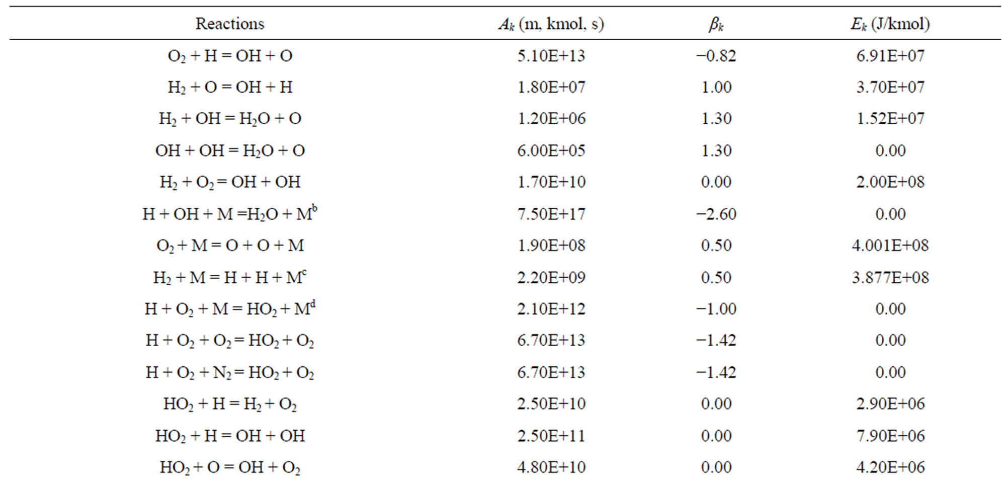
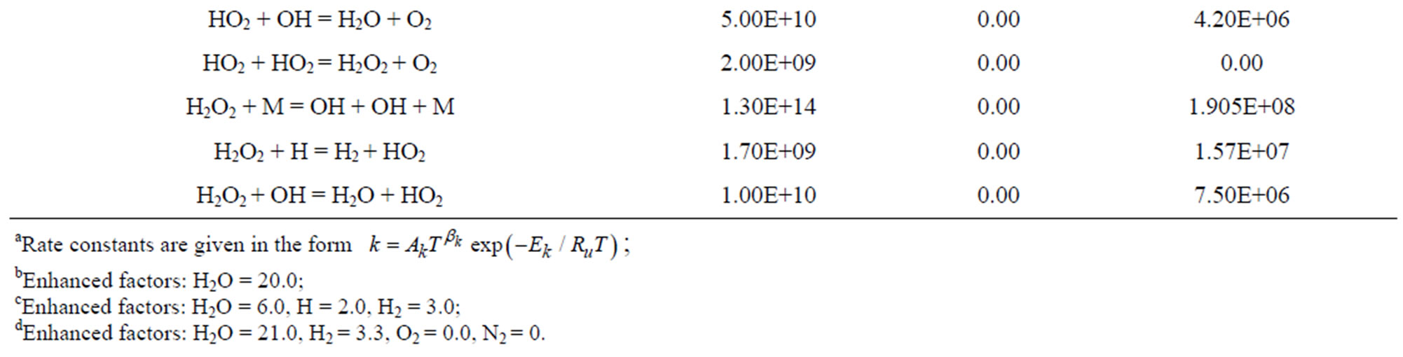
Table 1. Specified hydrogen air reactions with 9 species and 19 reactions.
2. Material and Methods
As shown in Figure 1, the experiment set up consisted of 3 sub-systems namely: fuel supply and control system, combustion system and testing system. The entire system was operated at room condition with ambient temperature spanning 295 to 300 K. Fuel supply and control system comprised of the hydrogen tank, air compressor, mass flow rate controller and pipes. Hydrogen and air were used as fuel because hydrogen has the advantages of high power density, fast flame speed and short reaction time. The hydrogen and air flow rates were controlled by two Brooks Mass Flow Controllers with an accuracy of 1% of the full scale. The combustion system included a connecting tube, 4 connectors and 4 micro combustors. Micro combustors were connected on the connectors by threaded bolts, and the 4 connectors were designed to produce a more uniform flow profile before entering the micro combustors. The testing system consisted of a high-performance RAYTEK Infrared thermometer (Model MA2SSCF, with an accuracy of ± (0.3%T + 1) K), a high precision Mitutoyo Height Gauge with an accuracy of 0.001 mm and a PC. The infrared thermometer was used to measure the wall temperature of micro combustors. The distance from the thermometer to the spots to be tested was 300 mm. The height gauge was used to control the testing position of thermometer. Taking reference from the baseline of the wall, a total of 10 temperature readings were recorded for each experiment.
Between the combustors and connectors, stainless steel wire meshes were employed. The holes on the mesh were small enough to prevent the back flow of the hydrogen flame. The error associated with each experimental measurement was computed to be 5%.
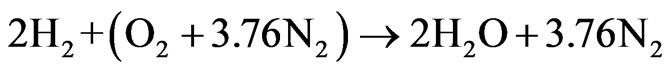
As shown in Figure 2, a cross flow heat exchanger, performing the function of heat recuperator, has been designed to recover the heat from the exhaust gas.
For a complete combustion of hydrogen in air, the overall chemical reaction can be written as
 (1)
(1)
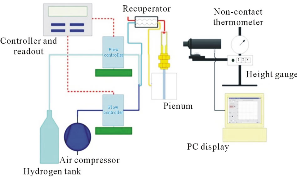
Figure 1. Schematic of the experiment set up.
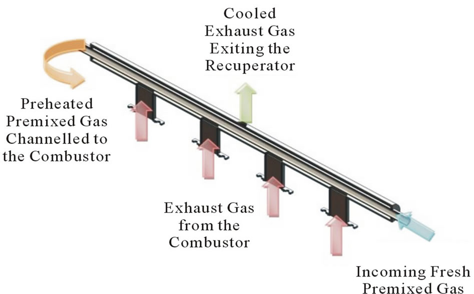
Figure 2. Working mechanism of the recuperator.
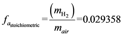
This stoichiometric relation is based on the assumption that the simplified composition for air is 21%  and 79%
  by volume. The stoichiometric hydrogen-air ratio can be expressed as:
 (2)
(2)
In which,  is expressed as:
 (3)
(3)
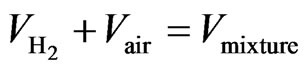
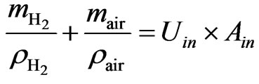
The flow rates of H2 and air can be determined by considering the conservation of mass within the plenum. At the combustor inlet, it can be observed that:
 (4)
(4)
By applying ideal gas law and with the assumption of constant pressure and temperature in the plenum,
 (5)
(5)
 (6)
(6)
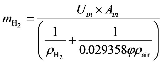
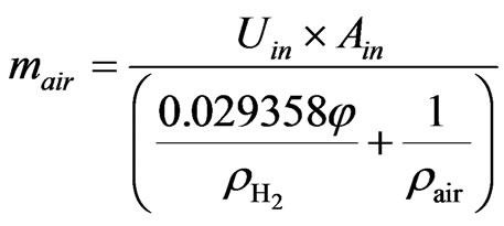
The mass flow rates equations for  and air can be written as:
 (7)
(7)
 (8)
(8)
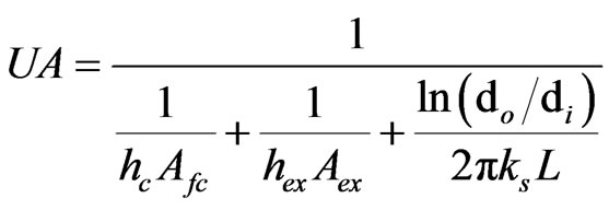
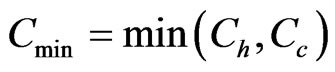
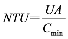
The heat transfer between exhaust gas and intake gas is calculated by NTU method for cross flow heat exchanger. In the calculation of NTU, fouling factor is ignored in calculating the heat transfer coefficient:
 (9)
(9)
A simple calculation reveals that the thickness of the centre tube has little effect on the overall heat transfer of the recuperator.
 (10)
(10)
 (11)
(11)
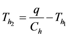
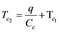
The outlet temperature of heat recuperator can be determined:
 (12)
(12)
 (13)
(13)
The heat transfer coefficient is determined by Dittus Boelter equation which is applicable to premixed gas inside tube [19].
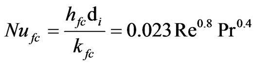 (14)
(14)
3. Computational Methods
The planar combustor employed in this study has internal dimensions of 10 mm × 1 mm × 17 mm with 0.5 mm wall thickness. The heat recuperator has a shell diameter of 10 mm and tube diameter of 5 mm. The exhaust gas flows through the shell side while the fresh gas flows through the tube. A 3-D model was built up.
The fluid medium can be regarded as to be in continuum as the Knudsen number is less than unity. That is the characteristic lengths of the models used are sufficiently large compared to the mean free path of air or hydrogen molecules. After the chemical energy is released in the combustor, an energy balance is achieved between the combustor and the environment. As a result, a steady-state model is employed. As the gas flowing through the combustor at a constant speed, the temperature effect caused by mass gradient can be neglected. Based on these, the following assumptions were made: 1) steady-state combustion, 2) no Dufour effects [20], 3) no work done by pressure and viscous forces, (4) insert wall with no surface reactions, 5) no gas radiation [21].
For continuity conservation:
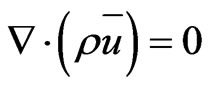 (15)
(15)
For momentum conservation:
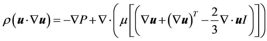 (16)
(16)
For energy conservation:
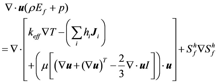 (17)
(17)
where  and
and  is the fluid enthalpy source term.
For species conservation:
 (18)
(18)
where  is the net rate of production of species I by chemical reaction,
  is the rate of creation by addition from the dispersed phase, and
  is the diffusion flux of species I which is given by
 (19)
(19)
A detailed hydrogen-air reaction mechanism with 9 species and 19 reactions is employed to simulate the hydrogen combustion. Based on the governing equations listed above, the 3-D model is solved by Fluent Release 14.0 [22]. SIMPLE algorithm which is convenient to solve the coupling between pressure and velocity has been employed to discretize the governing equations. The residuals for continuity, momentum, and species are set as 1 × 10⁻³ for the criteria of convergence. 1 × 10⁻⁶ is set as the energy convergence criterion. A massfractionweighted average method is utilized to compute the viscosity, constant pressure specific heat and thermal conductivity of the hydrogen and air mixture. A piecewise polynomial fitting method is employed to calculate the specific heat of each species. A mesh independence study is performed to get better accuracies as well as to reduce the computational time. The calculation error can be neglected as the mesh size is 0.1.
The pressure drop in heat exchanger is defined as
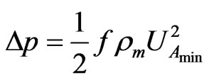 (20)
(20)
where f is the streamwise pressure drop coefficient which is expressed as
 (21)
(21)
where  is the entrance loss coefficient,
  is the exit loss coefficient,
  is the core friction factor,
  is the specific volume at the exit,
  is the specific volume at the inlet,
  is the mean specific volume.
The wall thermal conductivity is taken to be 20 W/m2K. At the inlet plane, the mixture enters the combustor with a uniform temperature 300 K. Heat loss from the noninsulated wall to the ambient are given by
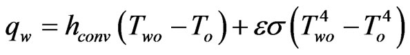 (22)
(22)
where the convective heat transfer  and the wall emissivity
  are taken to be 5
  and 0.78, respectively.
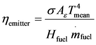
The efficiency of micro combustor is defined as the ratio of the net radiation power emitted by emitter to the chemical energy input flow. Planck’s distribution shows the emissive power of a blackbody as a function of wavelength,  , at different temperatures.
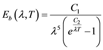 (23)
(23)
where  and
and

By Stefan-Boltzmann law, the total emissive power per unit surface area of a black body can be determined from
 (24)
(24)
where 
The efficiency of the micro combustor is defined as
 (25)
(25)
where  is the mass flow rate of the hydrogen,
  corresponds to the emissive surface area of micro combustor that will be utilized to emit photon for PV cell and
  is the wall emissivity.
4. Results and Discussion
4.1. Model Validation
Adopting the various assumptions to simplify the complexity of the model, we expect an acceptable degree of variance between the numerical results and experimental results. From the comparison of the mean wall temperature between the numerical result and experimental result, (Figure 3) differences of 40 - 105 K are observed. This translates into 3.6% - 8.5% temperature differences. From the comparison of the gas temperature between numerical result and experimental result, only an around 33 K difference was observed, which translates into a 5%. Hence, as depicted, the numerical result generally in good agreement with experimental result, thereby confirming the validity of the simplified model.
It is noteworthy that the numerical temperature data are higher than experimental results for all equivalence ratios. This observation may be attributed to the assumptions made in the computational methods and involving deviation from the real condition.
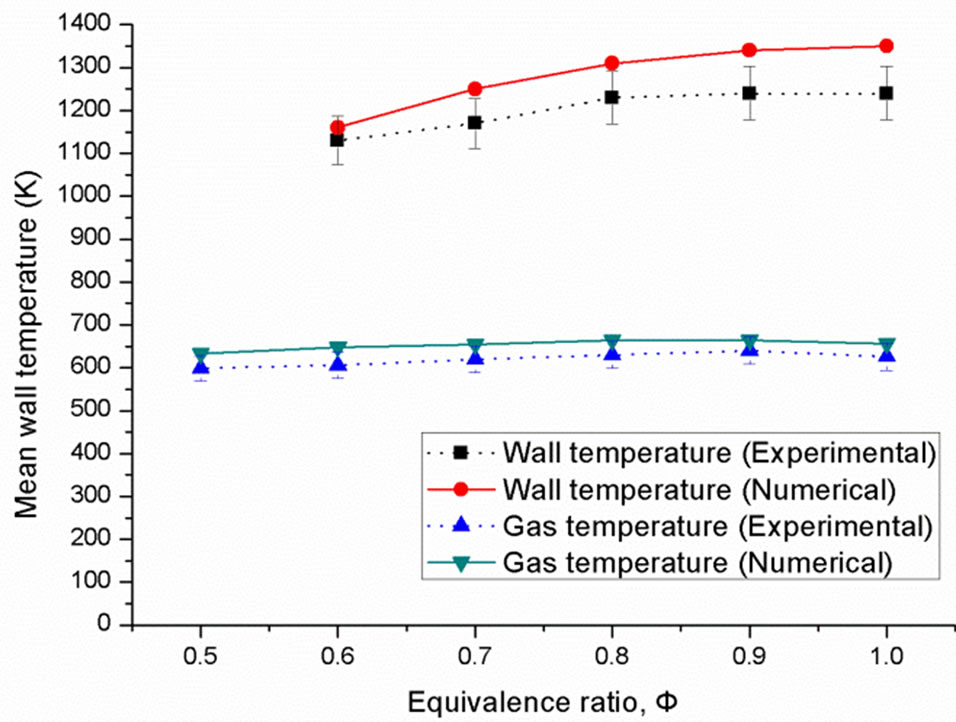
Figure 3. Comparing between mean wall temperature and gas temperature based on numerical and experimental results.
4.2. Effect of Inlet Pipe Numbers
Micro combustors with single and double inlet pipes are employed in the experiment. The hydrogen/air mixture flows through the inlet pipe and enters the combustors for burning. Figures 4 and 5 show the temperature distributions of the micro modular combustors with single inlet pipe for both simulation and experiment. Symmetric distributions are obtained in both numerical and experimental results. It is apparent that the temperature distribution is non-uniform where the two central combustors have comparatively higher temperature than the two combustors located at the sides. This fact indicates that the design with single inlet pipe is not suitable for the micro modular TPV system application. An obvious temperature gradient can be observed between the top and the bottom of the connector. The temperature gradient on the connectors may be attributed to the thermal conduction from high temperature zone to the ambient temperature zone through the wall. A more combustors uniform distribution can be observed among the four with double inlet pipes as shown in Figures 6 and 7 which is caused by the equally supplied hydrogen/air mixture. There exist marginal differences between numerical and experimental results. This is due to the oxidizing of wire meshes between combustors and connectors in the experiment. After a long combustion duration, the meshes potentially become oxidized and may block the flow at certain region. This can account for the differences between numerical and experimental results.
Figure 8 shows the temperature profile along the surface of the combustors with single inlet pipe. As can be observed in the figure, the temperature profile of central combustors is higher than the side combustors. This kind of phenomena shows the same law as Figures 4 and 5. A good agreement between simulation result and
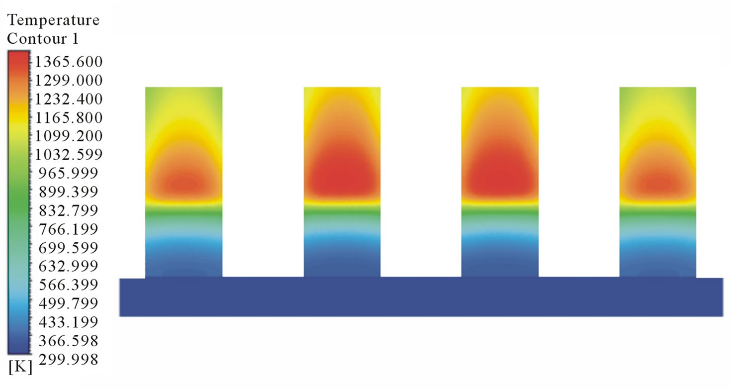
Figure 4. Numerical results showing the temperature distribution of single inlet pipe combustor.
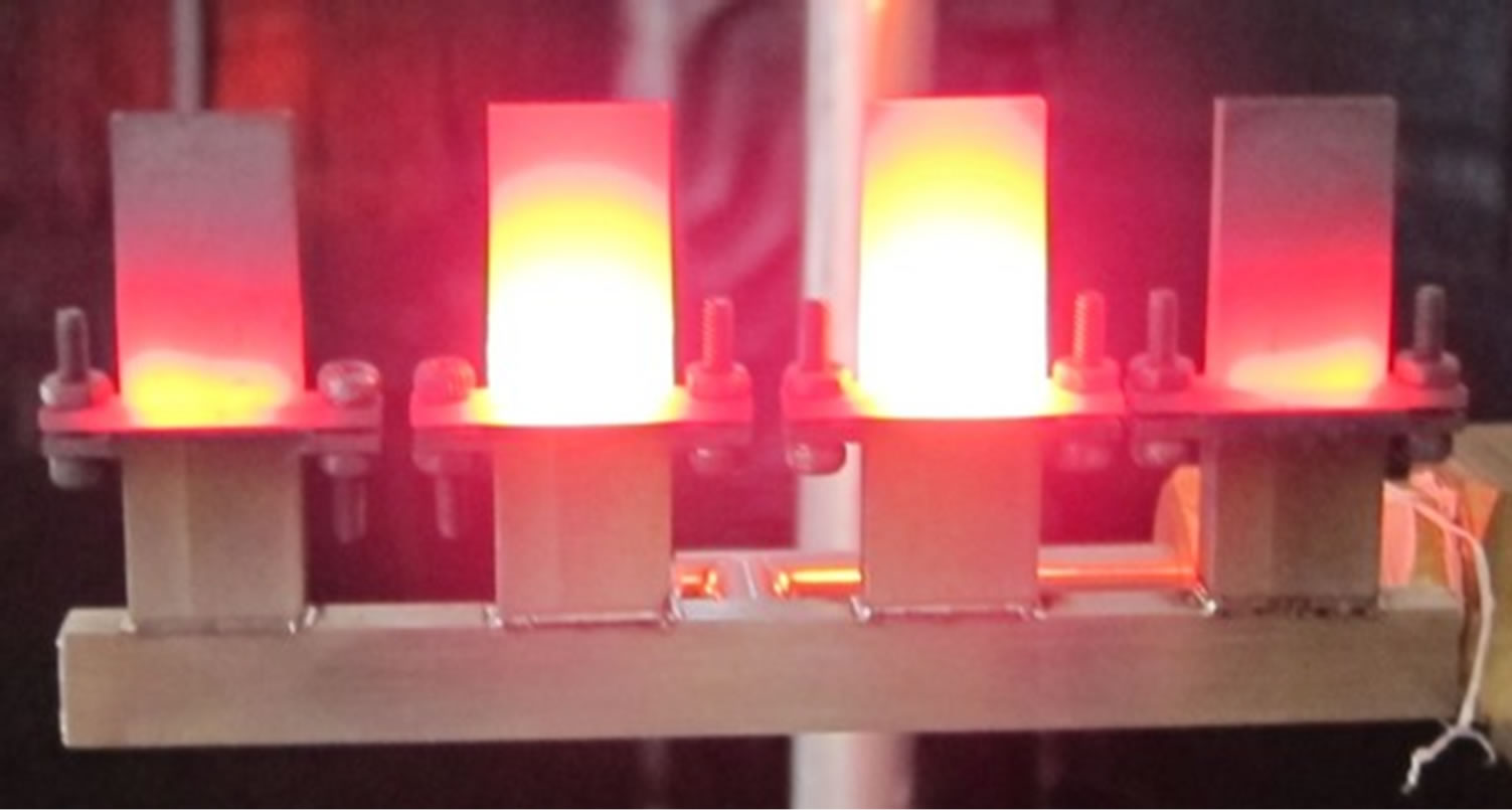
Figure 5. Experimental results showing the temperature distribution of single inlet pipe combustor.
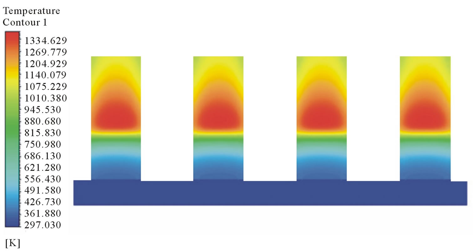
Figure 6. Numerical results showing the temperature distribution of double inlet pipes combustor.
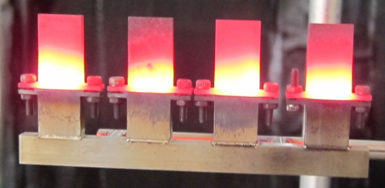
Figure 7. Experimental observation of the temperature distribution of douopble inlet pipes combustor.
experimental result is obtained. The highest temperature of the central combustor is 1468.15 K as measured in the experiment and 1411.48 K in the simulation. The highest temperature of the side combustor is 1128.15 K in the experiment and 1185.59 K in the simulation. Compared to simulation result, the temperature difference between the central combustor and side combustor is larger in the experiment. This is because that the two central combustors got higher temperature at the early stage of combustion and resulted in the density of burned gas becoming lower than that in the side combustors. This mechanism could generate more suction force at the two central combustors and enlarge the temperature difference with the side combustors. Figure 9 shows the temperature profile of the central combustor in the double inlet pipes design. The largest difference between simulation and experimental results is computed to be 3%. The temperature profile of experimental result is decreasing from inlet to the outlet which is due to the heat losses on the combustor walls. The highest temperature of double inlet pipes combustor is 1340.15 K as measured in the experiment and 1356.97 K in the simulation.
4.3. Effect of Equivalence Ratio
From Figure 10, it can be observed that there is an increase of 71 - 160 K in mean wall temperature when the inlet gas is preheated by the recuperator. As the equivalence ratio is increased from 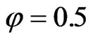 to 1.0, more fuel is available for combustion. This results in greater heat released and higher wall temperature. Nevertheless, as the equivalence ratio approaches the stoichiometric value, the increase in mean wall temperature is reduced and becomes negative. This may be attributed to the fact that combustion speed increases as the equivalence ratio approaches the stoichiometric value. Hence, peak temperature occurs very early and this will result in higher
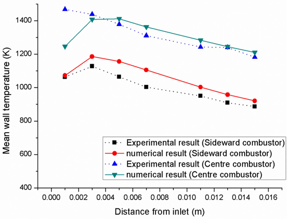
Figure 8. Temperature profile of the single inlet pipe com.
Figure 9. Temperature profile of the double inlet pipes combustor.
heat loss through the combustor wall by natural convection.
Another interesting phenomenon we have observed in the simulation is that at lower equivalence ratios, the flame tends to shift to a position that is very close to the exit. Conversely, as  increases, the location of the maximum flame temperature is shifted upstream. This phenomenon has also been observed by Yang et al. [23]. It can be explained by the ratio of flow velocity and the reaction rate. The concentration of
  molecules decreases simultaneously with
 . As a result, it gives rise to the need for a longer length scale.
4.4. Effect of Inlet Flow Velocity
Though the preheated gas using recuperator in a micro combustor tends to achieve higher peak temperature compared to one without heat recuperation at the same velocity, it is subjected to greater heat loss by natural convection since the peak temperature occurs earlier for preheated gas. As shown in Figure 11, at velocities of 2 m/s and 3 m/s, the increase in peak temperatures is offset
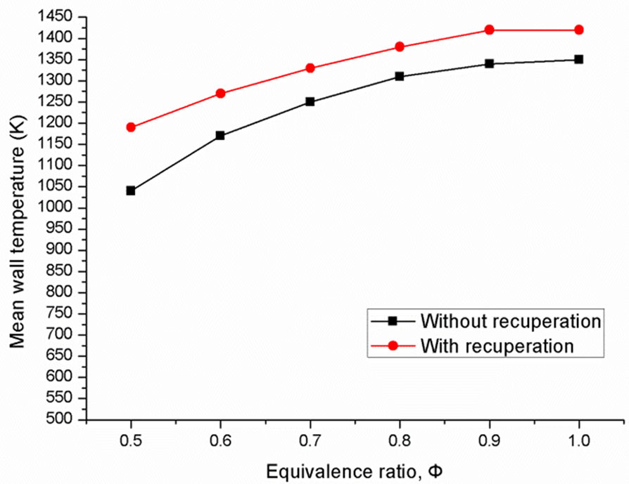
Figure 10. Mean wall temperature within the combustor with different equivalence ratio.
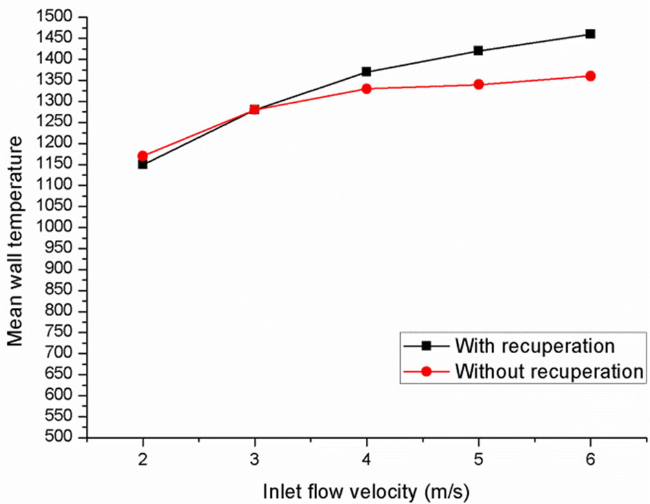
Figure 11. Mean wall temperature within the combustor with different inlet flow velocities.
by the heat loss due to natural convection; resulting in no significant increase in wall temperature. At higher velocities, the increase in peak temperatures is much higher in order to compensate for the heat loss by the convection. Hence, a significant increase of 40 - 100 K is observed.
With or without heat recuperation, at a fixed equivalence ratio, a higher flow velocity will increase the amount of fuel supplied for combustion per unit time. This results in a higher heat release rate and a higher mean wall temperature. Accordingly, the high temperature zone shifts downstream as the increment of velocity.
The increase in mean wall temperature is most significant for flows in lower velocity ranges. Further increase in flow velocity leads to an increase of  with decreasing rate. For example, at
  without recuperation, the increase in
  associated with the increase of flow velocity from 2 m/s to 3 m/s is 115.1 K, while for the increase in
  associate with the flow velocity spanning 5 m/s to 6 m/s is only 12.8 K. This phenomenon can be attributed to the incomplete combustion that occurs at higher flow velocity. Even though higher fuel input rates are obtained at high flow velocities, the residence time of the fuel decreases correspondingly. Incomplete combustion ensues. This effect is especially prominent for combustors designed at the micro scale level. On the other hand, this phenomenon is less significant for micro combustors incorporating heat recuperation because the preheated gas improves flame speed enhancing the probability of a complete combustion to take place.
4.5. Emitter Efficiency
From Figure 12, it can be observed that heat recuperation promotes better emitter efficiency by 5% - 10%. Since radiation power is markedly influenced by mean wall temperature, it follows the same trend as the mean wall
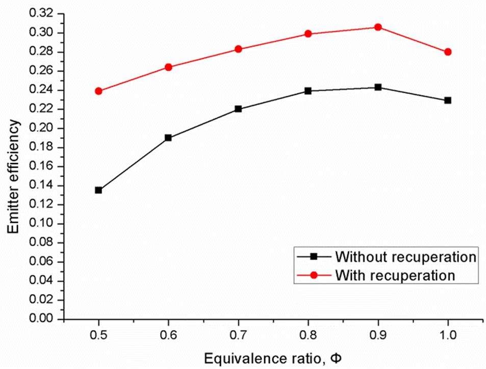
Figure 12. Emitter efficiency with fuel flow having different equivalence ratio.
temperature at different equivalence ratios. With higher equivalence ratios, greater amount of hydrogen is able to take part in the combustion process. Subsequently, the radiation power and input chemical energy are simultaneously enhanced. It is also indicative from Figure 12 that when the equivalence ratio is 0.9, highest emitter efficiency can be achieved for micro combustors with and without heat recuperation effects. Similar effect has also been noted by Pan et al. [24]. This could be because of the effect of equivalence ratio on the ignition position. As the equivalence ratio increases, more hydrogen releases chemical energy and leads to a higher efficiency. At the same time, the flame position move upstream nearer to inlet. When the equivalence ratio is higher than 0.9, the flame moves upstream and a part of chemical energy is released on the flange part which is treated as the heat loss to the environment.
However, for a micro TPV system, only photons with energy higher than the band gap of the PV cell are able to evoke free electrons. For instance, for a InGaAsSb PV cells with a band gap of 0.55 eV, only photons with a wavelength shorter than 2.5  are considered useful [16]. This is the key reason why a high temperature radiative power with short wavelength is highly desirable and greatly sought after in a micro TPV system design.
5. Conclusions
In the present study, a double-inlet pipes combustor incorporating a recuperator which is capable of utilizing the waste heat to preheat the incoming fresh premixed gas has been designed and studied. A numerical model validated with experimental data has been formulated in this study. Numerous simulations have been conducted with the model. By employing the double inlet pipes combustor, a more uniform temperature distribution can be achieved. The recuperator is able to elevate the temperature of the incoming reactants from ambient temperature to 400 - 470 K depending on the exhaust gas temperature from the combustor and the velocity of the gas. A temperature increase spanning 71 - 160 K can be observed when the reactants are preheated by the recuprator. It is predicted that higher inlet flow velocity also produces higher mean wall temperature due to the increase amount of fuel being supplied for combustion per unit time. The increment of emitter efficiency is signifycant when heat recuperation is introduced. Incorporating heat recuperation to a micro combustor can enhance its emitter efficiency by 5% - 10%.
The major contribution of this study is the demonstration of heat recuperator which is capable of utilizing the waste heat to preheat the incoming fresh premixed gas. The concept of using waste heat to improve the energy efficiency performance is important. Besides, as the fabrication cost is concerned, it is also advantageous over a long time operation.
REFERENCES
- L. C. Chia and B. Feng, “The Development of a Micropower (Micro-Thermophotovoltaic) Device,” Journal of Power Sources, Vol. 165, No. 1, 2007, pp. 455-480. doi:10.1016/j.jpowsour.2006.12.006
- S. K. Chou, W. M. Yang, K. J. Chua, J. Li and K. L. Zhang, “Development of Micro Power Generators—A Review,” Applied Energy, Vol. 88, No. 1, 2011, pp. 1-16. doi:10.1016/j.apenergy.2010.07.010
- K. J. Chua, W. M. Yang and W. J. Ong, 2012, “Fundamental Experiment and Numerical Analysis of a Modular Microcombustor with Silicon Carbide Porous Medium,” Industrial & Engineering Chemistry Research, Vol. 51, No. 18, pp. 6327-6339. doi:10.1021/ie203017g
- A. H. Epstein and S. D. Senturia, “Macro Power from Micro Machinery,” Science, Vol. 276, No. 5316, 1997, p. 1211. doi:10.1126/science.276.5316.1211
- C. Lee, “Design and Fabrication of a Micro Wankel Engine Using MEMS Technology,” Microelectronic Engineering, Vol. 73-74, 2004, pp. 529-534. doi:10.1016/S0167-9317(04)00206-0
- I. A. Waitz, G. Gauba and Y.-S. Tzeng, “Combustors for Micro-Gas Turbine Engines,” Journal of Fluids Engineering, Vol. 120, No. 1, 1998, pp. 109-117. doi:10.1115/1.2819633
- F. Lu, H. P. Lee and S. P. Lim, “Modeling and Analysis of Micro Piezoelectric Power Generators for Micro-Electromechanical-Systems Applications,” Smart Materials and Structures, Vol. 13, No. 1, 2004, pp. 57-63. doi:10.1088/0964-1726/13/1/007
- G. J. Snyder, J. R. Lim, H. Chen-Kuo and J. P. Fleurial, “Thermoelectric Microdevice Fabricated by a MEMSLike Electrochemical Process,” Nature Materials, Vol. 2, No. 8, 2003, pp. 528-531. doi:10.1038/nmat943
- W. M. Yang, S. K. Chou, C. Shu, Z. W. Li and H. Xue, “Development of Microthermophotovoltaic System,” Applied Physics Letters, Vol. 81, No. 27, 2002, pp. 5255- 5257. doi:10.1063/1.1533847
- K. Kim, D. Le and S. Kwon, “Effects of Thermal and Chemical Surface—Flame Interaction on Flame Quenching,” Combustion and Flame, Vol. 146, No. 1-2, 2006, pp. 19-28. doi:10.1016/j.combustflame.2006.04.012
- A. Veeraragavan and C. P. Cadou, “Flame Speed Predictions in Planar Micro/Mesoscale Combustors with Conjugate Heat Transfer,” Combustion and Flame, Vol. 158, No. 11, 2011, pp. 2178-2187. doi:10.1016/j.combustflame.2011.04.006
- J. Li, S. K. Chou, Z. W. Li and W. M. Yang, “Experimental Investigation of Porous Media Combustion in a Planar Micro-Combustor,” Fuel, Vol. 89, No. 3, 2010, pp. 708-715. doi:10.1016/j.fuel.2009.06.026
- S. K. Chou, W. M. Yang, J. Li and Z. W. Li, “Porous Media Combustion for Micro Thermophotovoltaic System Applications,” Applied Energy, Vol. 87, No. 9, 2010, pp. 2862-2867. doi:10.1016/j.apenergy.2009.06.039
- J. H. Park, J. S. So, H. J. Moon and O. C. Kwon, “Measured and Predicted Performance of a Micro-Thermophotovoltaic Device with a Heat-Recirculating MicroEmitter,” International Journal of Heat and Mass Transfer, Vol. 54, No. 5-6, 2011, pp. 1046-1054. doi:10.1016/j.ijheatmasstransfer.2010.11.028
- J. A. Federici and D. G. Vlachos, “A Computational Fluid Dynamics Study of Propane/Air Microflame Stability in a Heat Recirculation Reactor,” Combustion and Flame, Vol. 153, No. 1-2, 2008, pp. 258-269. doi:10.1016/j.combustflame.2007.09.009
- W. Yang, S. Chou, K. Chua, H. An, K. Karthikeyan and X. Zhao, “An Advanced Micro Modular Combustor-Radiator with Heat Recuperation for Micro-TPV System Application,” Applied Energy, Vol. 97, 2012, pp. 749- 753. doi:10.1016/j.apenergy.2011.12.024
- B.-J. Tsai and Y. L. Wang, “A Novel Swiss-Roll Recuperator for the Microturbine Engine,” Applied Thermal Engineering, Vol. 29, No. 2-3, 2009, pp. 216-223. doi:10.1016/j.applthermaleng.2008.02.028
- J. C. G. Andrae and P. H. Bjornbom, “Wall Effects of Laminar Hydrogen Flames over Platinum and Inserted Surfaces,” American Institute of Chemical Engineers Journal, Vol. 46, No. 7, 2000, pp. 1454-1460. doi:10.1002/aic.690460718
- D. F. W, and L. M. K. Boelter, “Heat Transfer in Automobile Radiators of the Tubular Type,” University of California Publications in Engineering, Vol. 2, No. 13, 1930, pp. 443-461.
- F. A. Williams, “Combustion Theory: Fundamental Theory of Chemical Reacting Flow Systems,” 2nd Edition, Benjamin/Cummings, Menlo Park, 1985, pp. 265-293.
- D. G. Norton and D. G. Vlachos, “A CFD Study of Propane/Air Microflame Stability,” Combustion and Flame, Vol. 138, No. 1-2, 2004, pp. 97-107. doi:10.1016/j.combustflame.2004.04.004
- “Fluent 14.0 User’s Guide,” ANSYS, Inc., Canonsburg, 2011.
- W. M. Yang, D. Y. Jiang, S. K. Chou, K. J. Chua, K. Karthikeyan and H. An, “Experimental Study on Micro modular Combustor for Micro-Thermophotovoltaic System Application,” International Journal of Hydrogen Energy, Vol. 37, No. 12, 2012, pp. 9576-9583. doi:10.1016/j.ijhydene.2012.03.129
- J. Pan, J. Huang, D. Li, W. Yang, W. Tang and H. Xue, “Effects of Major Parameters on Micro-Combustion for Thermophotovoltaic Energy Conversion,” Applied Thermal Engineering, Vol. 27, No. 5-6, 2007, pp. 1089-1095. doi:10.1016/j.applthermaleng.2006.07.038
Nomenclature
NOTES
*Corresponding author.