International Journal of Nonferrous Metallurgy
Vol.2 No.3(2013), Article ID:33897,6 pages DOI:10.4236/ijnm.2013.23014
Microstructural Evolution in Cu-Mg Alloy Processed by Conform
1School of Materials Science and Engineering, Central South University, Changsha, China
2China Railway Construction Electrification Bureau Group Kang Yuan New Materials Co., LTD., Jiangyin, China
Email: songlp@csu.edu.cn
Copyright © 2013 Lianpeng Song et al. This is an open access article distributed under the Creative Commons Attribution License, which permits unrestricted use, distribution, and reproduction in any medium, provided the original work is properly cited.
Received December 25, 2012; revised January 25, 2013; accepted February 5, 2013
Keywords: Cu-Mg Alloy; Microstructural Evolution; Conform; Dynamic Recrystallization
ABSTRACT
The objective of this study is to investigate the possibility of continuous extrusion forming (Conform process) and microstructural evolution the of Cu-Mg alloy. The results indicate that Conform process can break as-cast grains and refine the structure, meanwhile. This process can improve the degree of the structure homogeneity. The TEM and EBSD techniques were used to investigate the morphology, grain size and misorientation of the samples at cavity entrance and cavity export. Refined structures after shear deformation include broken grains and subgrains formed by dislocation reconstruction. Due to the relatively high deformation temperature, dynamic recrystallization occurred during deformation. The subgrain rotation nucleation took place, and grain boundary migration resulted in grain growth. However, the coarse grains were refined by anneal twins.
1. Introduction
Conform continuous extrusion forming process has been most widely used in the efficient continuous production of soft aluminum alloys rod, tube, sections and cored products, as well as copper wires, rectangular sections and a wide range of copper profiles [1-3], since the introduction of this methodology by the Atomic Energy Authority in UK (UKAEA) early in 1970s, due to its superiority of pre-heating-free, energy-saving, high extrusion ratio and production efficiency, production with large length and high homogeneity and so on [4,5].
Similar to ECAP (equal channel angular pressing), severe plastic deformation technique was performed using a tool steel die with two channels intersecting at an inner angle of 90˚ [6-11]. The schematic of the Conform process is shown in Figure 1. In principle, the feedstock is fed into the profiled groove of the extrusion wheel by means of a coining roll and the groove closed by a close fitting shoe. The material is prevented from continuing its passage around the wheel by means of an abutment [12,13]. As a result, high temperatures and pressures are developed in the material, which becomes plastic and subsequently emerges from the machine through an extrusion die [14].
The microstructural evolution and grain refinement during ECAP have been well documented [15]. Previous studies indicate that grain refinement is predominately operated by accumulation, interaction, tangling and spatial rearrangement of dislocations [16-18]. However, due to the large deformation heat produced by metal plastic deformation process of Conform, the microstructural evolution has not been reported. The main purpose of the present study is to research the microstructural evolution during Conform process.
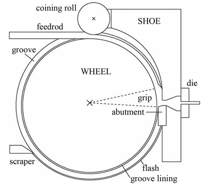
Figure 1. A schematic view of Conform process.
2. Materials and Experimental Procedures
The Cu-0.45 Mg alloys were prepared by melting high purity cathode copper, high purity magnesium in a 3000 kg industrial inductive furnace, then the ingots were cast by the upward casting system. The rods were extruded by TLJ500 Conform machine which was manufactured by Dalian Railway Institute. The parameters of extrusion process were extrusion temperature of 650˚C, wheel angular velocity of 4.0 r/min. Figure 2 shows the photograph of copper block in cavity obtained in the interrupted extrusion production. The copper samples at cavity entrance and export were researched.
To evaluate the microstructural evolution during the process, transmission electron microscopy (TEM) observations were performed on a transmission electron microscope FEI TECNAIG2 at 200 kV. Thin foil samples were electropolished in a twin-jet instrument using a mixture of 30% hydrogen nitrate with alcohol as the balance. The SEM examination was conducted with a KYKY-2800 type scanning electron microscope under control voltage 20 kV, and equipped electron backscatter diffraction (EBSD) was utilized to investigate the fracture behavior and quantitative analysis of grain and subgrains.
3. Results
3.1. Microstructure Developed during the Conform Process
The microstructure of Cu-Mg alloy rod before Conform process is shown in Figure 3(a). It can be found that coarse equiaxed grains and dendritic structure exist in the as-cast Cu-Mg alloy, the average grain size is about 2000 µm. Figure 3(b) shows the microstructure of Cu-Mg alloy after Conform process. It can be found that the structure was consisted of fine grains. The evolution of microstructure shows that the as-cast structure is transformed into equiaxial and fine grains. So Conform process is an effective method to refine the as-cast grain
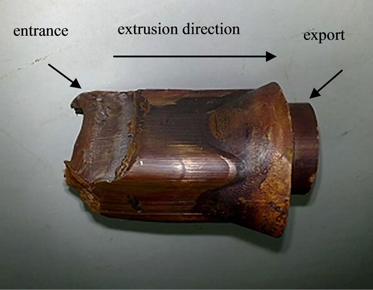
Figure 2. A photograph of copper block in cavity.
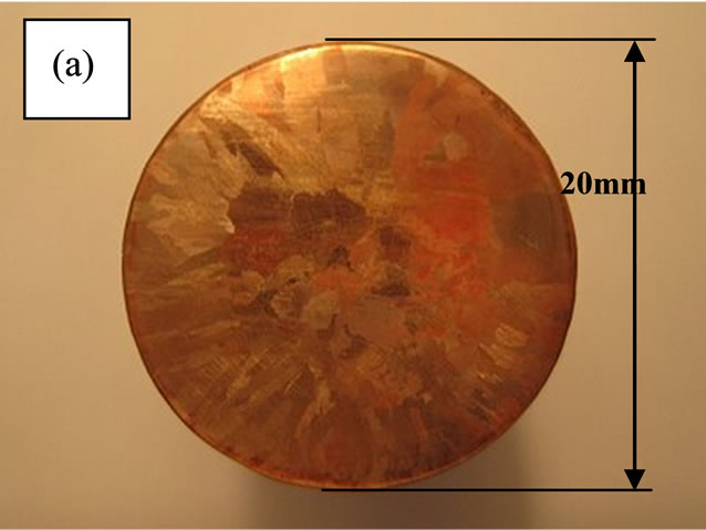
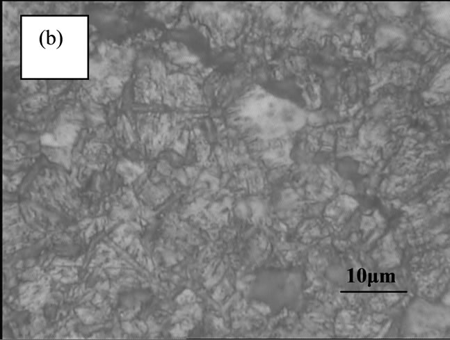
Figure 3. Optical micrographs of Cu-Mg alloy (a) before Conform process (b) after Conform process.
structure in copper, and can be successfully applied to the continuous deformation of Cu-Mg alloy.
3.2. EBSD Characterization of Cu-Mg Alloys
In order to characterize the homogeneity of microstructure during Conform process on a smaller scale, the advanced EBSD technique was used to investigate the morphology, grain size and misorientation distributions of samples ar cavity entrance and cavity export. From the corresponding EBSD images in Figures 4(a) and (b), it can be seen that the microstructure of sample at the cavity entrance is consisted of high-angle grains, and the grain sizes are about 10 µm. However, the grain boundaries are not clearly observed (Figure 4(a)), which are caused by substructures consisting primarily of subgrains of small misorientation after shear deformation [19]. The grain boundaries can be be clearly observed for the sample at the cavity export, and a lot of small-size grains and twins are shown in Figure 4(b). These grains showed well-defined grain boundaries, suggesting the presence of a large fraction of high angle grain boundaries. It’s worth mentioning that recrystalllization has occurred in die cavity, possibly due to the heat generated during the deformation.
Grain size distributions of corresponding samples are shown in Figure 5(a). When subgrain sizes are considered, the grain sizes of the sample at entrance range from 0.3 to 10.3 µm after shear deformation, with average grain size of 4.94 µm (Figure 5(a)). After annealing at
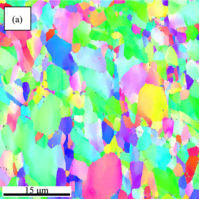
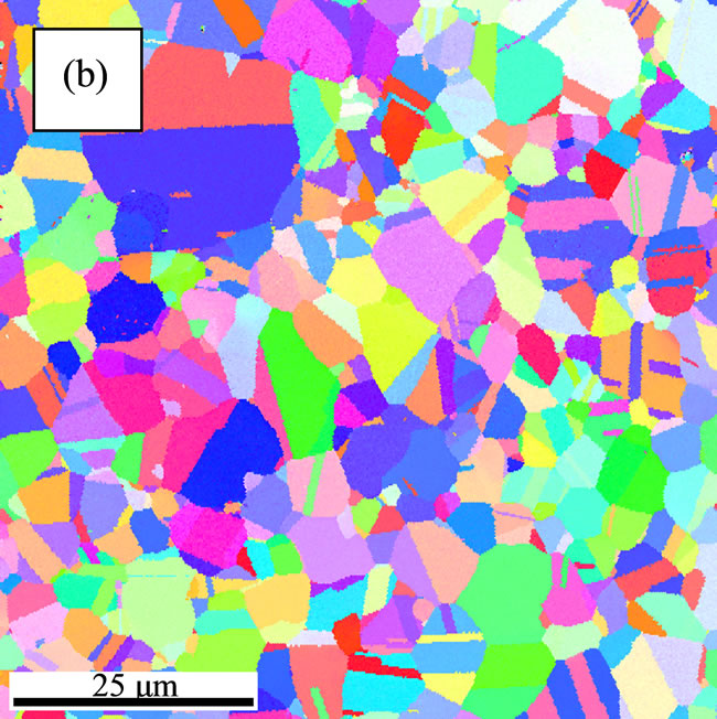
Figure 4. EBSD maps concerning microstructures of Cu-Mg alloy after Conform (a) sample at the cavity entrance (b) sample at the cavity export.
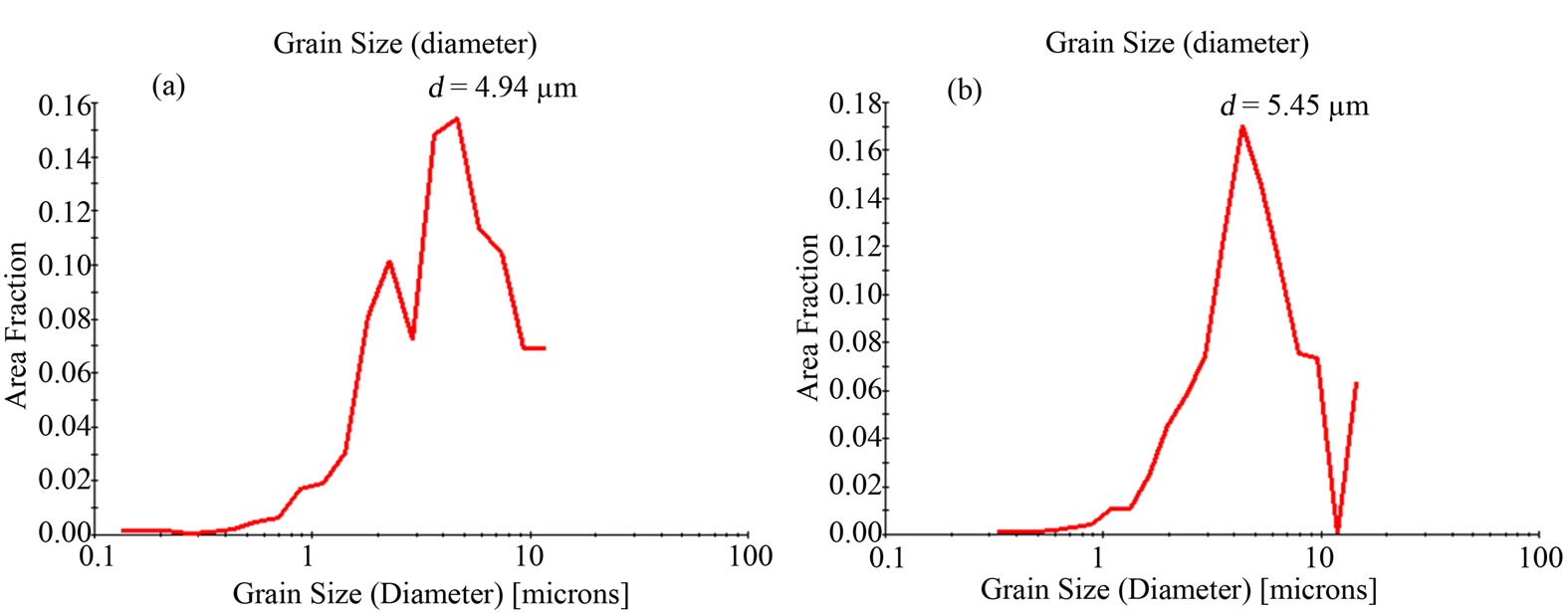
Figure 5. Grain size distributions of Cu-Mg alloy alloys obtained by EBSD (a) cavity entrance’s sample (b) cavity export’s sample
the cavity, the average grain size changes to 5.45 µm. It’s worth noting that some grains have grown up at the cavity.
The distributions of the misorientation angles of corresponding samples are presented in Figures 6(a) and (b), respectively. The volume fraction of low-angle grain boundaries that powerfully substantiates the formation of the relatively homogeneous fine microstructures after shearing deformation is about 60%. However, from the data, the corresponding fraction of the low-angle grain boundaries of the extruded product is about 27%, which is essentially lower than that of sample at the cavity entrance. From this difference, we can conclude that some low-angle grain boundaries had transformed to highangle grain boundaries during deformation. Meanwhile, the volume fraction of misorientation angles of 60˚ has increased up to 33.8% for the sample at the cavity export.
4. Discussion
According to the EBSD data, the grains have been refined to 4.94 µm after shear deformation at the cavity entrance. There are two reasons for the refinement. One is severe plastic deformation that increases the misorientation of geometrically necessary boundaries and incidental boundaries leading to the formation of high-angle grain boundaries, as well as smaller grains inside the original coarse grains, this is the well-known dislocation subdivision mechanism [20-23]. The other is the subgrains forming in the broken grains, which are separated by low-angle grain boundaries (Figure 7(a)). The second reason can be explained by that the dislocation distribution produced by shear deformation is apt to be replaced by energetically favorable subgrains. The subgrain formation evidences in broken grains were observed in Figure 7(b). Lots of dislocation entangle in position A and form dislocation-tangle zone. At high deformation temperatures, annealing of deformed metals results in the decrease of the number of dislocations in the cell’s interior while the dislocations tangle in the cell walls and change into more regular dislocation networks. The reconstruction was observed in position B. Then the dislocation walls gradually transform into subboundaries such as dense-dislocation wall (position D) and uncondensed dislocation wall (position C), and cells transform into subgrains free of dislocations. Thermal energy assists in creating “clean” boundaries. Meanwhile, it is to be noted that the deformation time for subgrain formation is extremely low (−2.5 × 10 − 5 s) [24], that’s why a large number of subgrains form in short time.
Due to the relatively high deformation temperature, dynamic recrystallization occurred during deformation (Figure 8). The TEM examination has shown that the grain boundaries become smooth, and the density of dislocation is low. Lots of anneal twins have nucleaned and grown up during heat treantment. These evidences confirmed the occurrence of dynamic recrystallization due to the effect of heat and pressure, which is consistent with that shown in Figure 6 that the fraction of low-angle grain boundaries has decreased from 61% to 27%.
Anneal twins are apt to be formed in main slip system (twin plan: (111), angle: 60˚) [25-28]. According to EBSD data calculation, the fraction of twins formed in main slip system is 20.3%, that’s why misorientation angles of 60˚ increased greatly. Meanwhile, there is no change at the angles of 38.9˚, which means there is no twin formed in second slip system (twin plan (110), angle 38.9˚). In Figure 9, a new grain (T) formed at the triple point between grains E, F and G. The location of
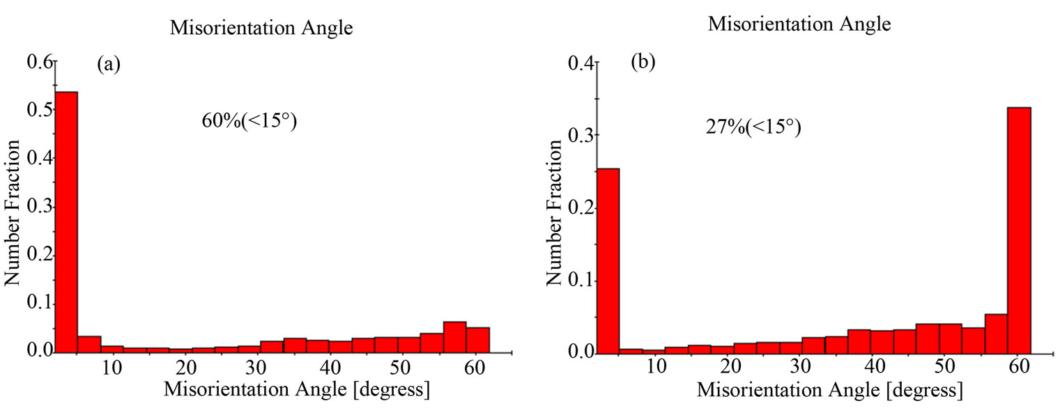
Figure 6. Misorientation angle distributions of Cu-Mg alloy alloys obtained by EBSD (a) sample at the cavity entrance (b) sample at the cavity export.
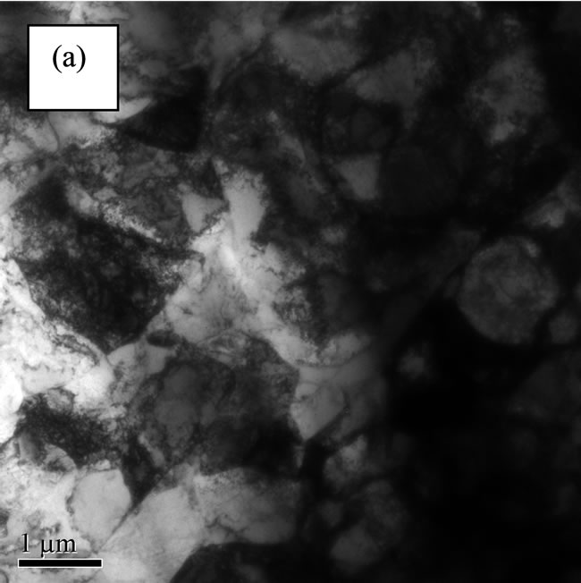
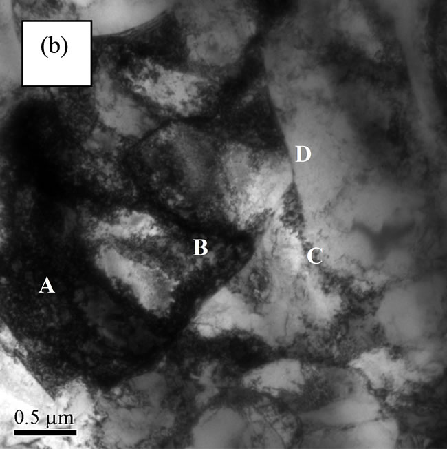
Figure 7. Bright-field TEM images of cavity entrance’s sample (a) TEM micrographs of microstructures (b) TEM images of subgrain formation.
Figure 8. Bright-field TEM images of sample at the cavity export (a) dislocation in grain (b) twins and ledge of boundary migration.
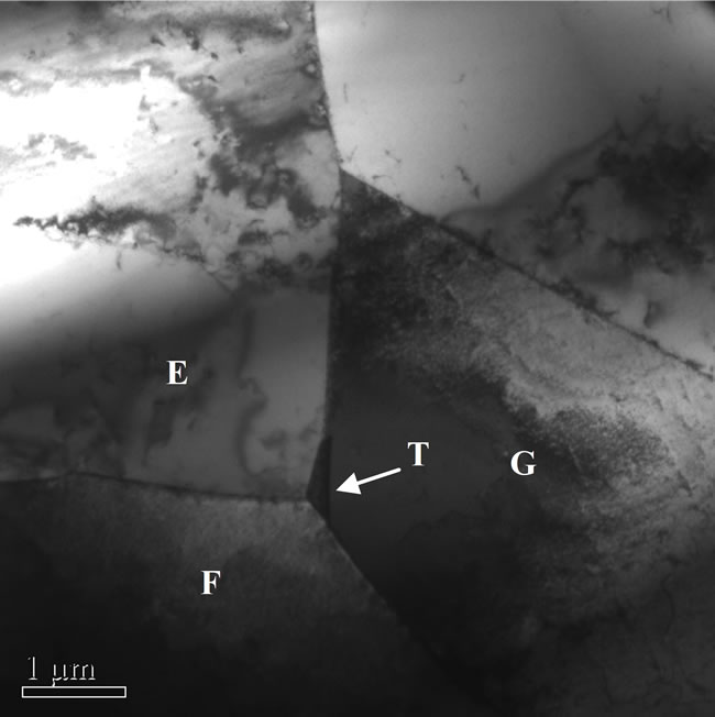
Figure 9. A new grain T formed at the triple point between grains E, F and G.
the new grains in the structure appears to be more favorable for their growth. According to Ref. [29], the grain (T) is twinned with grain G, and the energy of the boundary GT is lower than that of GF and GE, because the energy of the coherent twin boundary GT is very low, there may be a reduction in total boundary energy despite the extra boundary area created. So the anneal twins will refine the coarse-grain structure.
5. Conclusions
Continuous extrusion forming (Conform process) was an effective method to refine the cast grain structure in copper and can be successfully applied to Cu-Mg alloy. From the TEM and EBSD observation, the grains have been refined to 4.94 µm after shear deformation. However, due to the relatively high deformation temperature, dynamic recrystallization occurs during deformation. The average grain size changes to 5.45 µm.
By comparing to the microstructural evolution in Conform process, broken grains which composed of dislocations formed during shear deformation, meanwhile, subgrains formed by dislocation reconstruction.
Due to the relatively high deformation temperature, dynamic recrystallization occurred during deformation. The fraction of the low-angle grain boundaries decreased from 60% to 27%. According to EBSD data calculation, the fraction of twins formed in main slip system (twin plan: (111), angle: 60˚) is 20.3%. That’s why misorientation angles of 60˚ increased greatly.
6. Acknowledgements
The authors would like to thank School of Materials Science and Engineering of Central South University for the financial support and provision of research facilities used in this work.
REFERENCES
- C. Etherington, “CONFORM—A New Concept for the Continuous Extrusion Forming of Metals,” Transactions of the American Society of Mechanical Engineers, Journal of Engineering for Industry, Vol. 96B, No. 3, 1974, pp. 893-900.
- S. Harper, “Special Extrusion Processes for Non-Ferrous Metals,” The Metallurgist and Materials Technologist, Vol. 12, No. 5, 1980, pp. 257-260.
- T. Reinikainen, A. S. Korhonen, K. Anderson and S. Kivivuori, “Computer-Aided Modelling of a New Copper Extrusion Process,” Annals of CIRP, Vol. 42, No. 1, 1993, pp. 265-268. doi:10.1016/S0007-8506(07)62440-8
- D. Green, “Continuous Extrusion-Forming of Wire Section,” Journal of the Institute of Metals (London), Vol. 100, 1972, pp. 295-300.
- C. Etherington, “Continuous Extrusion Forming of Metals,” Transactions of the American Society of Mechanical Engineers, Series B, Vol. 96, No. 3, 1968, pp. 893-900.
- Z. Horita, T. Fujinami, M. Nemoto and T. G. Langdon, “Improvement of Mechanical Properties for Al Alloys Using Equal-Channel Angular Pressing,” Journal of Materials Processing Technology, Vol. 117, No. 3, 2001, pp. 288-292. doi:10.1016/S0924-0136(01)00783-X
- W. Z. Han, S. D. Wua, S. X. Li and Y. D. Wang, “Intermediate Annealing of Pure Copper during Cyclic Equal Channel Angular Pressing,” Materials Science and Engineering A, Vol. 483-484, 2008, pp. 430-432. doi:10.1016/j.msea.2006.10.179
- A. Azushima, R. Kopp, A. Korhonen, D. Y. Yang and F. Micari, “Severe Plastic Deformation (SPD) Processes for Metals,” CIRP Annals: Manufacturing Technology, Vol. 57, 2008, pp. 716-735. doi:10.1016/j.cirp.2008.09.005
- A. Mishra, V. Richard, F. Grégori, R. J. Asaro and M. A. Meyers, “Microstructural Evolution in Copper Processed by Severe Plastic Deformation,” Materials Science and Engineering A, Vol. 410-411, 2005, pp. 290-298. doi:10.1016/j.msea.2005.08.201
- M. Kawasakia, Z. Horitab and T. G. Langdona, “Microstructural Evolution in High Purity Aluminum Processed by ECAP,” Materials Science and Engineering A, Vol. 524, No. 1-2, 2009, pp. 143-150. doi:10.1016/j.msea.2009.06.032
- A. A. Gazder, F. Dalla Torre, C. F. Gu, C. H. J. Davies and E. V. Pereloma, “Microstructure and Texture Evolution of bcc and fcc Metals Subjected to Equal Channel Angular Extrusion,” Materials Science and Engineering A, Vol. 415, No. 1-2, 2006, pp. 126-139. doi:10.1016/j.msea.2005.09.065
- I. V. Alexandrov and R. Z. Valiev, “Nanostructures from Severe Plastic Deformation and Mechanisms of LargeStrain Work Hardening,” Nanostructured Materials, Vol. 12, No. 5-8, 1999, pp. 709-712. doi:10.1016/S0965-9773(99)00223-8
- T. Manninen, T. Katajarinne and P. Ramsay, “Analysis of Flash Formation in Continuous Rotary Extrusion of Copper,” Journal of Materials Processing Technology, Vol. 177, No. 1-3, 2006, pp. 600-603. doi:10.1016/j.jmatprotec.2006.04.051
- L. P. Lu, X. B. Yun, J. Y. Yang and B. Y. Song, “Study on Deforming Behavior of Copper-Magnesium Alloy Wire in Extending Continuous-extrusion Process,” Hot Working Technology, Vol. 39, 2010, pp. 92-95.
- S. Qu, X. H. An, H. J. Yang, C. X. Huang, G. Yang, Q. S. Zang, Z. G. Wang, S. D. Wu and Z. F. Zhang, “Microstructural Evolution and Mechanical Properties of Cu-Al Alloys Subjected to Equal Channel Angular Pressing,” Acta Materialia, Vol. 57, No. 5, 2009, pp. 1586-1601. doi:10.1016/j.actamat.2008.12.002
- P. B. Prangnell, A. Gholinia, V. M. Markushev, “The Effect of Strain Path on the Rate of Formation of High Angle Grain Boundaries during ECAE,” In: T. C. Lowe and R. Z. Valiev, Eds., Investigations and Applications of Severe Plastic Deformation, Kluwer Academic Publisher, Dordrecht, 2000, pp. 65-71. doi:10.1007/978-94-011-4062-1_9
- Y. Iwahashi, Z. Horita, M. Nemoto and T. G. Langdon, “The Process of Grain Refinement in Equal-Channel Angular Pressing,” Acta Materialia, Vol. 46, No. 9, 1998, pp. 3317-3331. doi:10.1016/S1359-6454(97)00494-1
- Y. Iwahashi, Z. Horita, M. Nemoto and T. G. Langdon, “An Investigation of Microstructural Evolution during Equal-Channel Angular Pressing,” Acta Materialia, Vol. 45, No. 11, 1997, pp. 4733-4741. doi:10.1016/S1359-6454(97)00100-6
- F. J. Humphreys, “Review Grain and Subgrain Characterisation by Electron Backscatter Diffraction,” Journal of Materials Science, Vol. 36, 2001, pp. 3833-3854. doi:10.1023/A:1017973432592
- R. Z. Valiev, R. K. Islamgaliev and I. V. Alexandrov, “Bulk Nanostructured Materials from Severe Plastic Deformation,” Progress in Materials Science, Vol. 45, No. 2, 2000, pp. 103-189. doi:10.1016/S0079-6425(99)00007-9
- R. Z. Valiev and T. G. Langdon, “Principles of EqualChannel Angular Pressing as a Processing Tool for Grain Refinement,” Progress in Materials Science, Vol. 51, No. 7, 2006, pp. 881-981. doi:10.1016/j.pmatsci.2006.02.003
- Y. Iwahashi, Z. Horita, M. Nemoto and T. G. Langdon, “An Investigation of Microstructural Evolution during Equal-Channel Angular Pressing,” Acta Materialia, Vol. 45, No. 11, 1997, pp. 4733-4741. doi:10.1016/S1359-6454(97)00100-6
- Y. Iwahashi, Z. Horita, M. Nemoto and T. G. Langdon, “The Process of Grain Refinement in Equal-Channel Angular Pressing,” Acta Materialia, Vol. 46, No. 9, 1998, pp. 3317-3331. doi:10.1016/S1359-6454(97)00494-1
- A. Mishra, V. Richard, F. Gregori, R. J. Asaro and M. A. Meyers, “Microstructural Evolution in Copper Processed by Severe Plastic Deformation,” Materials Science and Engineering A, Vol. 410-411, 2005, pp. 290-298. doi:10.1016/j.msea.2005.08.201
- R. E. Reed-Hill, J. P. Hirth and H. C. Rogers, “Deformation Twinning,” Gordon and Breach, New York, 1964, p. 7.
- T. H. Blewitt, R. R. Coltman and J. K. Redman, “LowTemperature Deformation of Copper Single Crystals,” Journal of Applied Physics, Vol. 28, No. 6, 1957, pp. 651-660. doi:10.1063/1.1722824
- J. W. Christian and S. Mahajan, “Deformation Twinning,” Progress in Materials Science, Vol. 39, No. 1-2, 1995, pp. 1-157. doi:10.1016/0079-6425(94)00007-7
- A. Rohatgi, S. K. Vecchio and T. G. Gray III, “The Influence of Stacking Fault Energy on the Mechanical Behavior of Cu and Cu-Al Alloys: Deformation Twinning, Work Hardening, and Dynamic Recovery,” Metallurgical and Materials Transactions A, Vol. 32, No. 1, 2001, pp. 135-145. doi:10.1007/s11661-001-0109-7
- F. J. Humphreys and M. Hatherly, “Recrystallization and Related Annealing Phenomena,” Elsevier Ltd., Oxford, 2004, pp. 261-266.