Modern Research in Catalysis
Vol.1 No.3(2012), Article ID:23592,9 pages DOI:10.4236/mrc.2012.13006
Evaluation Performance of Different Types Catalysts of an Industrial Secondary Reformer Reactor in the Ammonia Plants
Department of Chemical Engineering, Basra University, Basra, Iraq
Email: *chemicalengineer82@yahoo.com
Received September 3, 2012; revised October 5, 2012; accepted October 15, 2012
Keywords: Fertilizers; Autothermal Reformer; Steam Reforming; Catalysis; Hydrogen Production.
ABSTRACT
In this paper, the effect of catalyst shape and characteristics has been investigated where five types of a catalyst were examined under the same operation conditions, where catalysts are similar in the chemical properties (Ni/MgOAl2O3) but it's different in their physical properties in the catalyst section of secondary reformer. The secondary reformer involves continuation of the methane reforming reaction that began in the primary reformer to produce Nitrogen and Hydrogen in the ammonia plant. In order to evaluate performance of various types of catalysts in the secondary reformer reactor, mathematical model have been created. The mathematical model covers all aspects of major chemical kinetics, heat and mass transfer phenomena in the secondary reformer in the ammonia plant at steady state conditions. It aims to optimize the best catalyst from five types of catalyst of the secondary reformer reactor in the State Company of Fertilizers South Region in the Basra/Iraq. The mathematical model allows calculating the axial variations of compositions, temperature and pressure of the gases inside two reactors in series by using the atomic molar balance and adiabatic flame temperature in the combustion section while, in the catalyst section, they are predicted by using a one-dimensional heterogeneous catalytic reaction model. The analysis evaluation performance of the catalyst (RKS-2-7H’) have good results than other the catalyst types (RKS - 2, ICI 54 - 2, RKS-2-7H”, RKS-2-7H”’) in catalyst zone of the secondary reformer.
1. Introduction
In a traditional ammonia plant, the secondary reformer is rather used downstream of the primary reformer in order to reform the unreacted methane to produce Hydrogen and Nitrogen.
The reactor consists of two sections, the combustion section is the empty space above the catalyst section is preferred to combust process gases with oxygen of the air to produce the Nitrogen while, the catalytic section is a fixed-bed reactor, in which the hydrocarbons are finally converted through heterogeneous catalytic reactions to produce the Hydrogen. It is provided with Ni/MgOAl2O3 as a catalyst, Finally, the Reformat Gases leaves the secondary reformer, as shown in the Figure 1.
1) Burner; 2) Combustion section; 3) Alumina bricks plate; 4) Alumina balls (dia. = 40 mm); 5) Catalyst section; 6) Alumina balls (dia. = 40 mm, 75 mm and 120 mm); 7) Cone.
The previous studies focuses on the secondary reformer in the ammonia plants or Autothermal reformer mainly Ali AL-Dhfeery and Ala’a Jassem [1], Akbar Zamaniyan
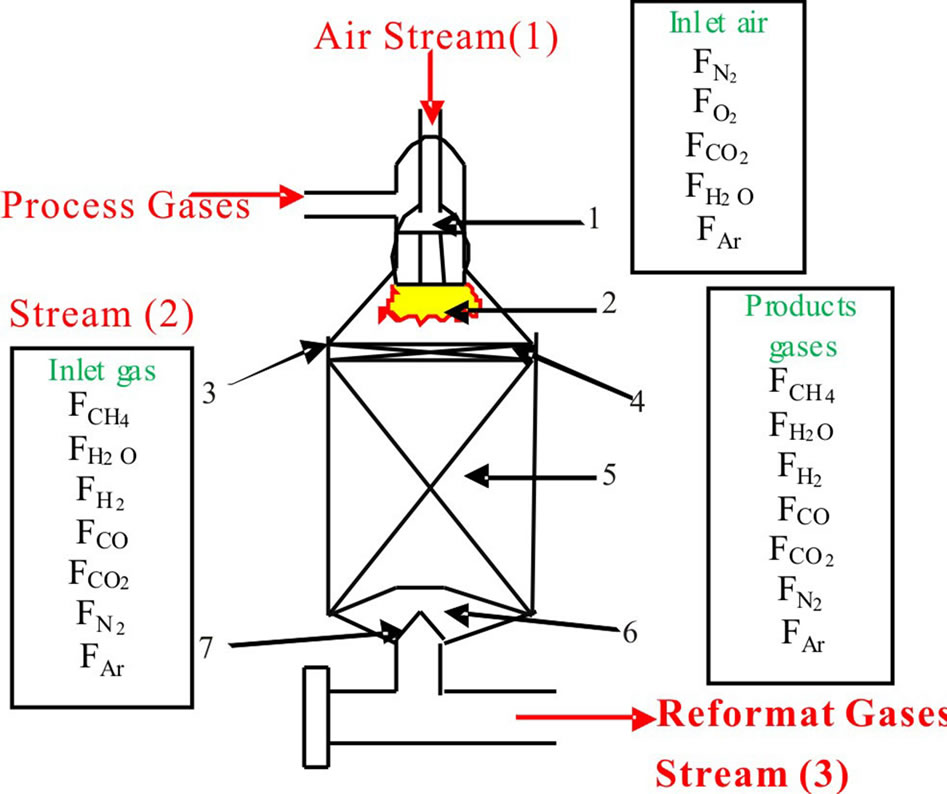
Figure 1. Schematic diagram of secondary reformer [1].
et al. [2], A. C. Juan Ruiz et al. [3], Kayvan Khorsand and Khadijeh Deghan [4], D. L. Hoang et al. [5], S. Vaccaro et al. [6], Mohd Idris Shukri et al. [7], Y. H. Yu [8], but in this study in the second reactor, bottom section, catalyst section, filled with nickel catalysts. Each catalyst will investigated alone then, the five different types will compared with each other to optimize the best catalyst from them, where catalysts are similar in the chemical properties (Ni/MgOAl2O3) but it’s different in their physical properties, the originality of the work lies in this proposal.
The results of mathematical model such as mole fraction, temperature profile and pressure drop of the combustion and catalyst zones of secondary reformer reactor in the State Company of Fertilizers South Region in the Basra/Iraq will be studied and compared relative to five different types of Ni-catalyst.
2. Experimental Section
The type of catalyst is considered one of the most important factors in industrial catalytic reactors which affect the conversion of reactants and the yield of the products.
The catalyst of reformer generally uses nickel catalysts due to high activity with high surface area to accelerate the reforming reactions.
A Ni-catalyst support on a magnesia-alumina spinel has used in the top of the catalyst bed in the secondary reformer reactor because it is activity and stability at high-temperature without breaking or shrinking where, the top of the catalyst bed is exposed to gases with high temperature of 1100˚C - 1400˚C [9].
A reforming catalyst, type RKS, is used for the steam reforming of natural gas. This catalyst is well suited for use in both, low temperatures in the primary reformer and at high temperatures in secondary and autothermal reformers for the production of hydrogen [10].
The nickel catalysts RKS-2 with one hole are packed with the volume of 26 m3, height of the catalyst bed 2.8 m with inside diameter of industrial secondary reformer reactor in ammonia unit in the State Company of Fertilizers South Region in the Basra/Iraq, is 3.45 m. The five various types of catalysts are used in a secondary reformer is summarized in Table 1.
3. Mathematical Model
In this section, the evaluation of performance for five different types of catalysts have been examined depending on the creating of a mathematical model relative to the actual operation conditions in the secondary reformer at Basrah Fertilizers Plant.
3.1. Modeling of Combustion Section
3.1.1. Chemical Reactions
The hydrocarbon (CH4) and oxygen in the air are mixed and combusted in the combustion section of secondary reformer reactor. Often the principle “mixed is burnt” is valid, since the exothermic combustion reactions are very fast.
The homogenous reactions are take place in the combustion section. The combustion reactions are numerous complex radical reactions, but for modeling purposes, it is often enough to describe the reactions by an overall one molecular reaction. In the case of natural gas, the
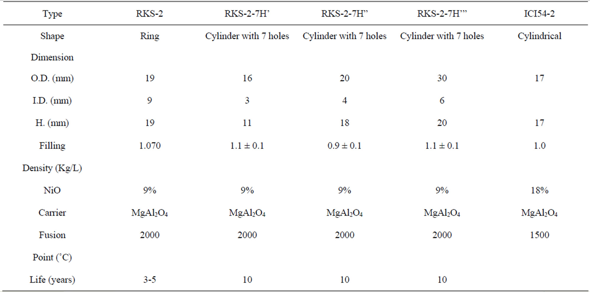
Table 1. Depicts types of catalysts using in secondary reformer [9-11].
combustion methane reaction can be written as follows:
 (1)
(1)
All oxygen is consumed in the combustion section, and the unconverted CH4 will continue down to the catalyst section. In the case of a secondary reformer also, H2 will be burnt to steam in the combustion section according to reaction.
 (2)
(2)
3.1.2. Mass and Heat Balances
The compositions and temperature of the gas in the combustion section is investigated by using simple mathematical model. The atomic molar balance and adiabatic flame temperature are used with assuming that the mixing between process gases and air is instantaneous in combustion section, and the conditions inside and outside of combustion section are same.
The atomic molar balance for each gas component in the combustion section can be derived as follows [1]:
 (3)
(3)
 (4)
(4)
 (5)
(5)
 (6)
(6)
 (7)
(7)
 (8)
(8)
 (9)
(9)
where,
 (10)
(10)
 (11)
(11)
 (12)
(12)
 (13)
(13)
 (14)
(14)
 (15)
(15)
The secondary reformer is operated close to adiabatically through, Adiabatic flame temperature can be described by the following Equation [12]:
 (16)
(16)
3.2. Modeling of Catalyst Section
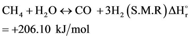
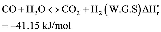
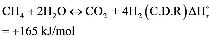
3.2.1. Chemical Reactions
The product gas from the combustion section is directed to the catalytic section of the secondary reformer. The catalyst bed involves three reversible reactions, which were thoroughly studied by Xu and Froment (1989). The first reaction is known as a Steam Methane Reforming reaction while the second and third reactions are called as Water Gas Shift reaction and Carbon Dioxide Reforming reaction respectively. Anyway, the following equations can be written as follows:
 (17)
(17)
 (18)
(18)
 (19)
(19)
The C-H bond of the stable methane molecule (CH4) has a high binding energy (439 kJ/mol) therefore, the dissociation reaction of steam methane reforming needs a high process temperature to shift the equilibrium compositions to the right side so the steam methane reforming reaction is endothermic [7].
3.2.2. Kinetics of the Reforming Reactions
The kinetics for the reforming reaction of methane on the Nickel catalyst based on the Alumina is according to study of Xu and Froment given in [1].
3.2.3. Effectiveness Factor Analysis
The effectiveness factor is an important parameter to predict the temperature and composition profiles for realizing the actual reaction rate with pore diffusion in the heterogeneous reaction. The effectiveness factor can be calculated by using the following equation [13]:
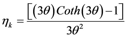 (20)
(20)
The Thiele Modulus can be estimated by the following equation [13]:
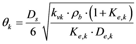 (21)
(21)
The catalyst pellets are assumed as spherical catalyst pellet with an equivalent volumetric diameter (Ds):
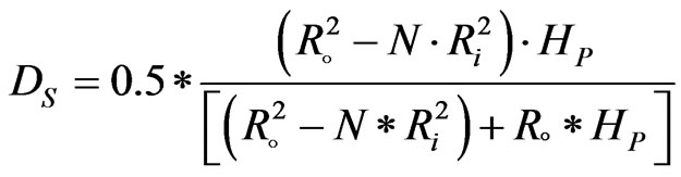 (22)
(22)
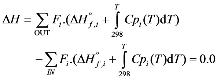
3.2.4. Mass, Heat and Momentum Balances
The concentration and temperature gradient is assumed to occur only in the axial direction while, the radial gradients temperature and composition are ignored because the reactor operates under adiabatic conditions. Through, the adiabatic one dimensional heterogeneous catalytic reaction model can be applied in the catalyst section by the following equations [8]:
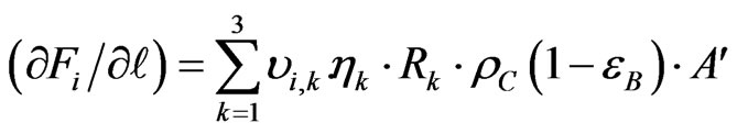 (23)
(23)
The change in the temperature gas on the length of reactor has been given [13]:
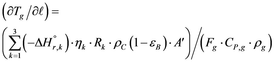 (24)
(24)
The catalyst surface temperature has calculated relative to the bulk gas temperature [8]:
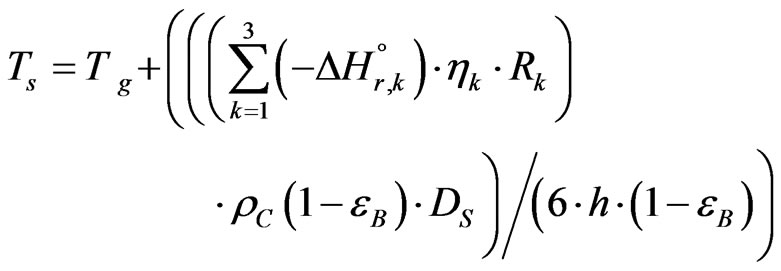 (25)
(25)
In the gas phase of packed bed catalytic reaction system, pressure drop is one of the important parameters. The pressure drop of outlet gases from catalyst section will be evaluated by using Ergun equation as follows [8]:
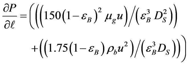 (26)
(26)
The solution procedure of mathematical model for five different types catalysts is solved equations of the heat and mass balances by Euler method.
4. Results and Discussion
4.1. Combustion Section
The actual operating conditions such as feed concentration, temperature and pressure have tabulated in Table 2. These data have used for modeling and evaluating the theoretical performance of industrial secondary reformer reactor. In addition to, there is no industrial data available in this section therefore they are not comparable.
4.2. Catalyst Section
In this section, the theoretical results predication from mathematical model have compared with the industrial data which collected from the manual and daily log sheet of Basra Fertilizer Plant where, the catalyst characteristics have been calculated from mathematical model for five different types catalysts as summarized in Table 3. The results depicted high accuracy between Simulation results and Plant Data [1].
4.2.1. Molar Flow Rates of Reactants and Products
In this section, the influence of the different types of catalysts is discussed with respect to the molar flow rates of reactants and products in the catalyst zone of the secondary reformer at Basrah Fertilizers Plant.
The relation between molar flow rates of gases as a function of the axial coordinate of catalyst bed has been described in Equation (23).
Figures 2-7 depict the effect of molar flow rates of methane, steam, Hydrogen, Carbon monoxide, Carbon di-
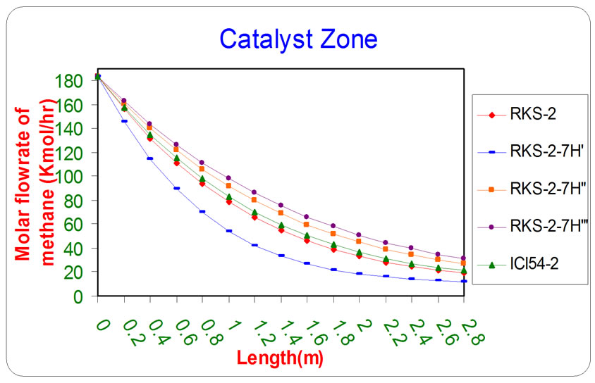
Figure 2. The influence of the difference types of catalyst on the molar flow rate of methane as a function of reactor length relative to inlet operation conditions (T = 1369.644 K & P = 32 bar).
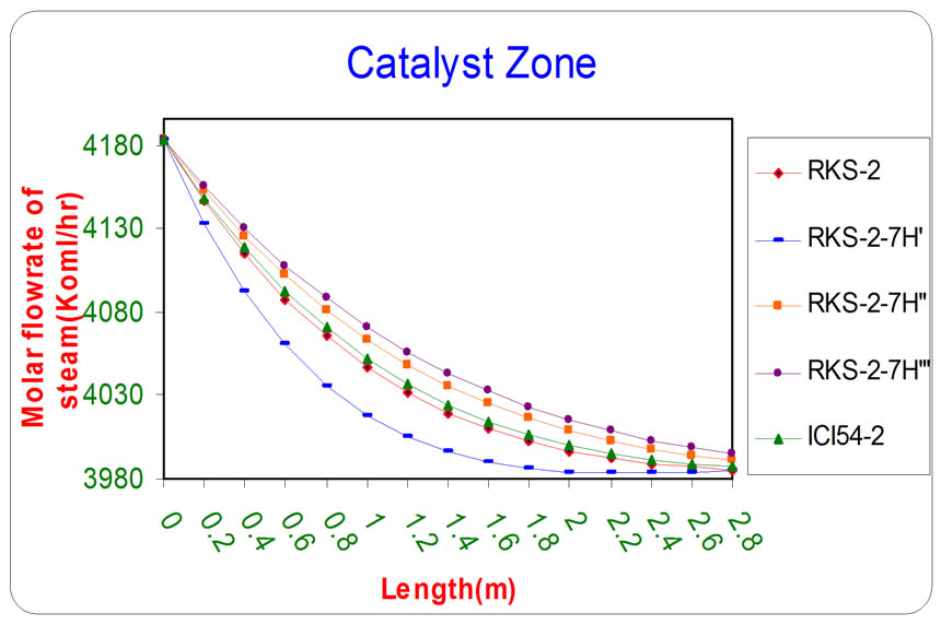
Figure 3. The influence of the difference types of catalyst on the molar flow rate of steam as a function of reactor length relative to inlet operation conditions (T = 1369.644 K & P = 32 bar).
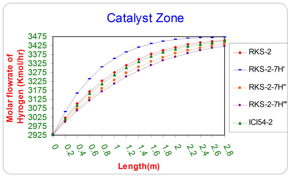
Figure 4. The influence of the difference types of catalyst on the molar flow rate of Hydrogen as a function of reactor length relative to inlet operation conditions (T = 1369.644 K & P = 32 bar).
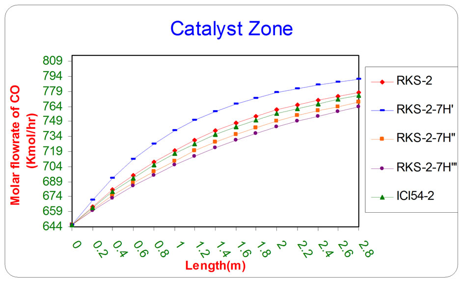
Figure 5. The influence of the difference types of catalyst on the molar flow rate of CO as a function of reactor length relative to inlet operation conditions (T = 1369.644 K & P = 32 bar).
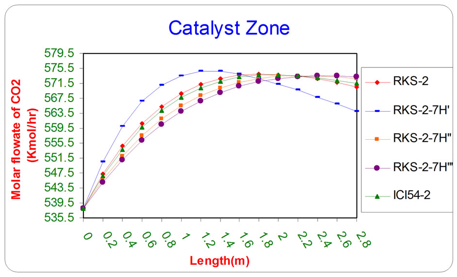
Figure 6. the influence of the difference types of catalyst on the molar flow rate of CO2 as a function of reactor length relative to inlet operation conditions (T = 1369.644 K & P = 32 bar).
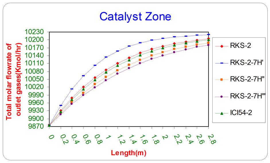
Figure 7. the influence of the difference types of catalyst on the total molar flow rate of outlet gases from catalyst section as a function of reactor length relative to inlet operation conditions (T = 1369.644 K & P = 32 bar).
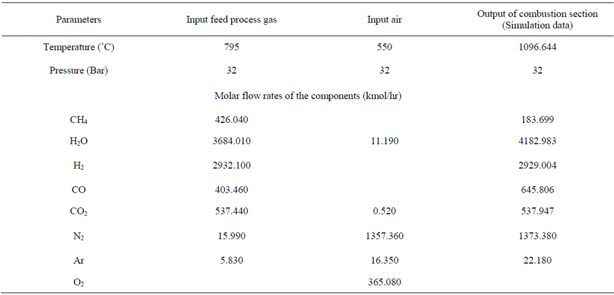
Table 2. Depicts the actual operations conditions of industrial secondary reformer in S.C.F.S.R. in Basra/Iraq with the simulation Data of the combustion section [14].
oxide and total molar flow rate of outlet gases respectively, as a function of length of catalyst section by using various types of catalysts (RKS - 2, RKS - 2 - 7H’, RKS - 2 - 7H”, RKS - 2 - 7H”’, ICI 54 - 2).
All the previous figures depict the catalyst (RKS-2- 7H’) was the best one relative to any other types. This is due to it appears more methane and steam consumption with more Hydrogen and carbon monoxides production.
4.2.2. Temperature Calculation for Gases and Catalyst Surface
The temperature is considered a very important factor due to the nature of chemical reactions on the catalyst section. These reactions are extended from endothermic to exothermic. The relation between the temperature of gases and surface of catalyst as a function for axial coordinate of catalyst bed has been described in Equations 24 and 25.
Figures 8 and 9 depict that the catalyst (RKS - 2 - 7H’) was more active than the other catalyst types (RKS - 2, ICI 54 - 2, RKS - 2 - 7H” and RKS-2 - 7H”’) respectively relative to the reactions conditions because the temperatures of gases and catalyst surface are lower than the temperatures in the other types of catalysts due to endthermic reactions that means the rate of reactions on the catalyst surface (RKS-2-7H’) are faster than other types of catalysts.
4.2.3. Pressure Drop
The pressure drop gives a good indication about catalyst performance inside the reaction shell because with a long time of operation; the catalyst may be thermal cracking due to high operation temperature so, the value of pressure drop will increase.
When the heat load per unit area is too high, smaller particles will be necessary in order to increase the surface area of the catalyst but, smaller particles will lead to increase the pressure drop. Therefore, selecting special
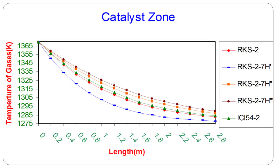
Figure 8. The influence of the difference types of catalyst on the temperature of gases as a function of reactor length relative to inlet operation conditions (T = 1369.644 K & P = 32 bar).
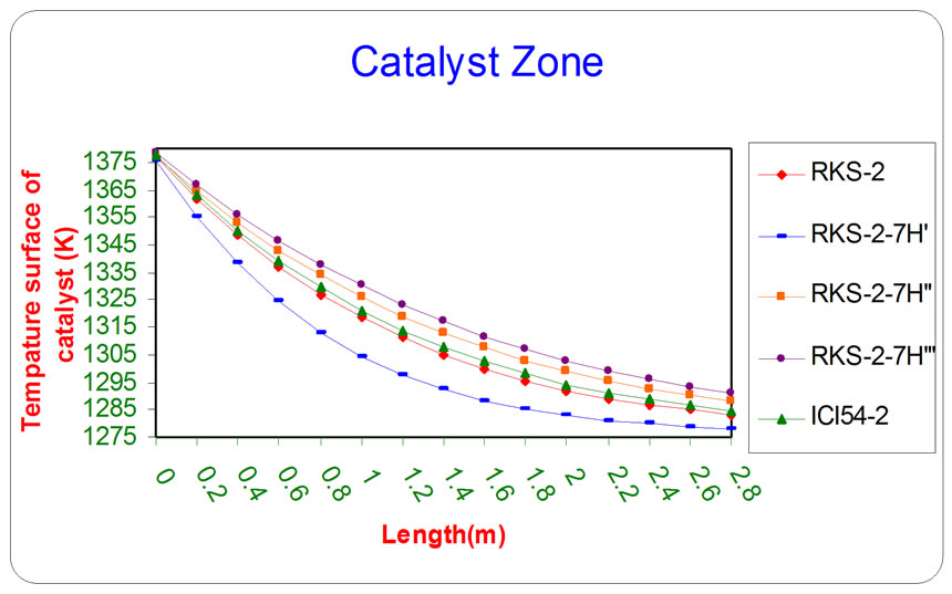
Figure 9. The influence of the difference types of catalyst on the temperature of catalyst surface as a function of reactor length relative to inlet operation conditions (T = 1369.644 K & P = 32 bar).
catalyst shapes such as rings or rings with several holes have been developed for these applications [11].
The behavior of pressure drop has been described in Equation (26) which depicts a decrease along the axial distance from the top of the catalyst bed.
Figure 10 depicts the value of outlet pressure as a function of reactor length for five different types of catalysts.
5. Conclusions
Secondary reformer for Hydrogen and Nitrogen production is mathematically investigated by a series of simulation of operation conditions which have collected from the documents of Basra Fertilizer Plant. Although, the catalyst (RKS-2) has been using in the secondary reformer at Basrah fertilizers plant but, the analysis evaluation performance of catalyst (RKS-2-7H’) had good results than the other catalyst types (RKS-2, ICI 54-2, RKS-2-7H” and RKS-2-7H”’) for several reasons as follows:
5.1. Gases Molar Flow Rates, Temperature of Gases and Catalyst Surface
This type of catalyst appears more methane and steam consumption with more Hydrogen and carbon monoxides production. Also, the temperatures of gases and catalyst surface are lower than the temperatures in the other types of catalysts due to endothermic reactions that means the rate of reactions on the catalyst surface (RKS- 2-7H’) are faster than other types of catalysts.
5.2. The Shape of Pellet
The shape of the catalyst pellet is considered a very important parameter. Rings with several holes are suitable shape amongst secondary reforming catalysts because it provides a higher surface area per unit volume i.e. the specific surface area of the pellets (S) as summarized in Table 3.
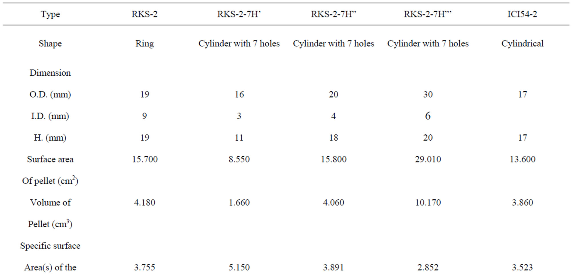
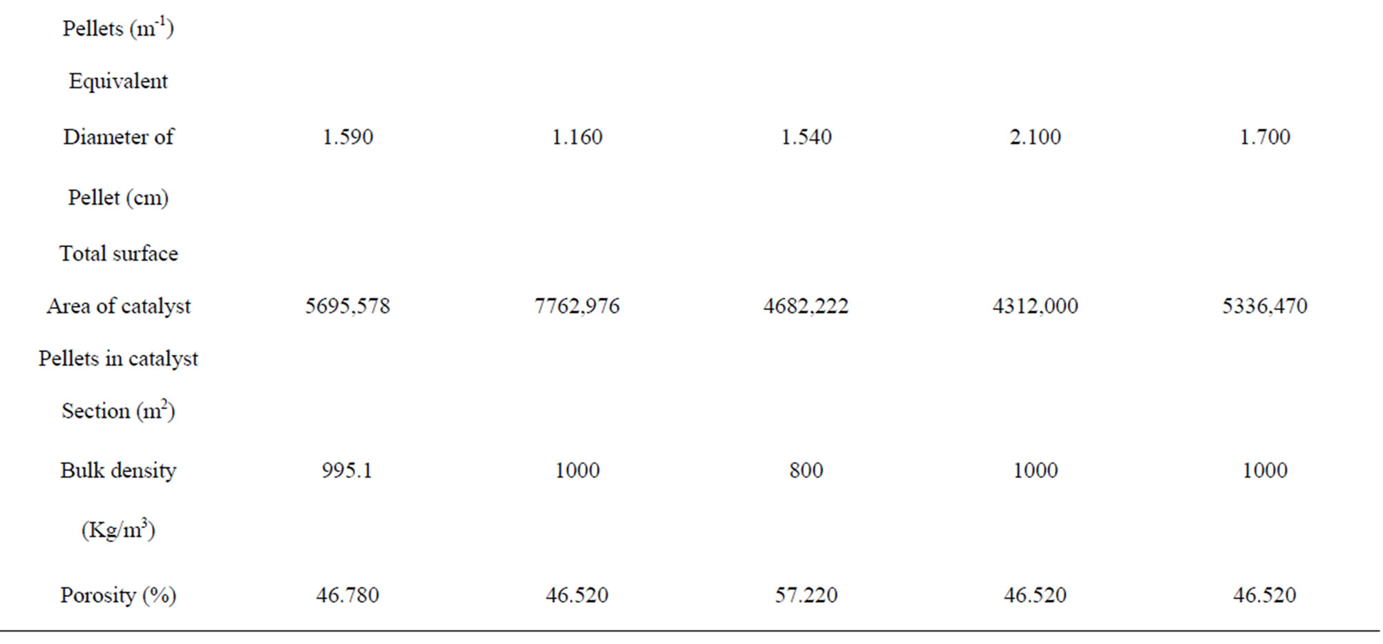
Table 3. Types of catalysts characteristics used in secondary reformer.
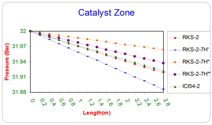
Figure 10. the influence of the difference types of catalyst on the pressure as a function of reactor length relative to inlet operation conditions (T = 1369.644 K & P = 32 bar).
The rings with several holes showed higher activities per unit volume than ordinary ring shaped catalysts.
5.3. The Total Surface Area of Catalyst Pellets in Catalyst Section
Using the smallest of the pellet in the catalyst zone is necessary for available high total surface area of catalyst pellets in catalyst section as shown in Table 3.
5.4. Volume of Pellet
The diffusion into the pellet is relatively slow, so that this condition mean reaction occurs before the reactant has diffused far into the pellet. Also, the effectiveness factor 
that means only the surface near from the outer surrounding of the pellet is effective, therefore, the diffusion and effectiveness factor gave a good indication about the shape of the catalyst that is used in the catalyst zone as a ring without central portion because the chemical reaction takes place at the outer surface [1], then the volume of RKS-2-7H’ pellet (Cylinder with 7 holes) has least volume of pellet because it has least dimensional and thin of walls than other pellets as shown in Table 3.
6. Acknowledgements
This work has been co-supported by the State Company Fertilizers Plant South Region to introduce industrial data for this investigation.
REFERENCES
- A. A. AL-Dhfeery and A. A. Jassem, “Modeling and Simulation of an Industrial Secondary Reformer Reactor in the Fertilizer Plants,” International Journal of Industrial Chemistry (IJIC), Vol. 3, No. 2012. doi:10.1186/2228-5547-3-14
- A. Zamaniyan, A. Behroozsarand and H. Ebrahimi, “Analysis of a Secondary Autothermal Reformer Using a Thermodynamic POX Model,” Journal of World Academy of Science, Engineering and Technology, Vol. 49, No. 25, 2009, pp. 247-251.
- J. A. C. Ruiz, F. B. Passos, J. M. C. Bueno, E. F. Souza-Aguiar, L. V. Mattos and F. B. Noronha, “Syngas Production by Autothermal Reforming of Methane on Supported Platinum Catalysts,” Applied Catalysis A: General, Vol. 334, No. 1-2, 2008, pp. 259-267. doi:10.1016/j.apcata.2007.10.011
- K. Khorsand and K. Deghan, “Modeling and Simulation of Reformer Autothermal Reactor in Ammonia Unit,” Journal of Petroleum and Coal, Vol. 49, No. 2, 2007, pp. 64-71.
- D. L. Hoang, S. H. Chan and O. L. Ding, “Hydrogen Production for Fuel Cells by Autothermal Reforming of Methane Over Sulfide Nickel Catalyst on a Gamma Alumina Support,” Journal of Power Sources, Vol. 159, No. 2, 2006, pp. 1248-1257. doi:10.1016/j.jpowsour.2005.11.094
- S. Vaccaro, G. Ferrazzano and P. Ciambelli, “Coupling of Catalytic Endothermic and Exothermic Reactions by CPR: Modeling and FEM simulation,” COMSOL Conference User, Millano, 2006.
- M. I. Shukri, A. R. Songip, A. Ahmad and N. S. Nasri, “Simulation Study of Methane Autothermal Reforming for Hydrogen Production,” Advanced in Fuel Cell Research, Fuel Cell Research Group, UTM, 2004, pp. 149- 158.
- Y. H. Yu, “Simulation of Secondary Reformer in Industrial Ammonia Plant,” Chemical Engineering Technology, Vol. 25, No. 3, 2002, pp. 307-314. doi:10.1002/1521-4125(200203)25:3<307::AID-CEAT307>3.0.CO;2-C
- G. W. Bridger and G. C. Chiclen, “Catalyst Handbook,” Wolrd Scientific, London, 1970.
- Mitsubishi Heavy Industries LTD MCEC, “Training Textbook,” Catalyst Manual of Ammonia Unit, Japan, 1977.
- H. Topsoe, “Topsoe Secondary Reforming Catalyst RKS- 2-7H,” www.topsoe.com
- R. M. Felder and R. W. Rousseau, “Elementary Principles of Chemical Processes,” 3rd Edition, John Wily & Sons Inc., Chichester, 2005.
- J. M. Smith, “Chemical Engineering Kinetics,” 2nd Edition, McGraw-Hill, New York, 1970.
- Mitsubishi Heavy Industries LTD MCEC, “Operation Manual,” Documents of State Company of Fertilizer Plant South Region, Japan, 1977.
Nomenclature
A’ = Cross section area (m2).
CP = Specific heat capacity (kJ/kmol.K).
De,k = Effective diffusivity of i-component for reaction k is defined as
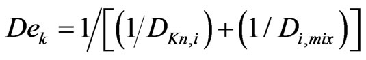 (m2/hr)
Di,mix = molecular diffusivity of i-component in the gas mixture .
.
DKn,i = Kndsun diffusivity of i-component .
.
DS = Equivalent pellet diameter (m). This is defined as the diameter of a sphere with the same external surface area per unit volume of the catalyst pellet. 
F = Molar flowrate (kmol/hr).
H = Heat transfer coefficient (kJ/m2. K.hr)  .
.
HP Height of pellet (m).
ΔH = Enthalpy change (kJ/kmol).
ΔHºf,i = Standard enthalpy of formation of i-component (kJ/mol).
ΔHor,k = Standard heat of reaction k (kJ/mol).
K = Thermal conductivity of gases (W/m.K).
Ke,k Equilibrium constant for reaction k (bar2) (except reaction number 2 dimensionless unit).
kυ,k The volumetric kinetic constant for reaction k (to convert unit of constant of reaction Rate) (m3/Kgcat.hr).
ℓ axial coordinates (m).
N Number of holes in the pellet of catalyst.
Nu Nessult number (dimensionless unit).
P Pressure of gases (Bar).
Q volumetric flowrate (m3/hr).
Pr Prandtl’s number (dimensionless unit).
Rk Rate of reaction for reaction k (kmol/Kgcat.hr).
R External radius of catalyst pellet of cylindrical shape (m).
Ri Inner radius of catalyst pellet of cylindrical shape (m).
S Specific surface area of the pellets (m–1), 
T Temperature (K).
u Velocity of gases (m/hr) 
Greek Letters
εB Porocity of packed bed (m3 void/mr3)
θ Thiele modules (dimensionless unit).
ηk Reaction effectiveness factor for reaction k (dimensionless unit).
μg Viscosity of gases (Pa.s).
υi Stoichiometric coefficient of i-component in the chemical reactions equations (dimensionless unit).
ρb Bulk density (kg/m3)
ρc Density of catalyst (kgc/mr3)
ρg Density of gases (kg/m3)
Abbreviations
C.D.R. Carbon Dioxide Reforming
IN Inlet stream
OUT outlet stream
S.C.F.R.S. State Company of Fertilizers South Region
S.M.R. Steam Methane Reforming
W.G.S. Water Gas Shift
NOTES
*Corresponding author.