International Journal of Clean Coal and Energy
Vol.2 No.3(2013), Article ID:36039,10 pages DOI:10.4236/ijcce.2013.23004
Economic Evaluation of the UCSRP-HP Process in IGCC Applications
Energy Conversion, Gas Technology Institute, Des Plaines, USA
Email: *arun.basu@gastechnology.org
Copyright © 2013 Arunabha Basu et al. This is an open access article distributed under the Creative Commons Attribution License, which permits unrestricted use, distribution, and reproduction in any medium, provided the original work is properly cited.
Received May 22, 2013; revised June 30, 2013; accepted July 8, 2013
Keywords: UCSRP-HP Technology; IGCC Power Plants; Synthesis Gas Clean-Up; IGCC Economics; Carbon Capture and Sequestration
ABSTRACT
With financial assistance from the US Department of Energy and the Illinois Clean Coal Institute, Gas Technology Institute (GTI) has been working with the University of California, Berkeley, for further development of their UCSRPHP (University of California Sulfur Recovery Process-High Pressure) technology. The key focus of the UCSRP-HP technology is integrated multi-contaminant removal of hydrogen sulfide (H2S), carbonyl sulfide (COS), ammonia (NH3), chlorides and heavy metals present in coal-derived syngas. The process has two major components: 1) removal of various trace components with a solvent (e.g., diethylene glycol or water) using a high-pressure scrubbing unit and 2) removal of H2S as sulfur via reaction with SO2 (in the presence of a solvent mixed a small quantity of a homogeneous catalyst) at 120˚C to 150˚C and at any syngas pressure. During this research, data critical to developing and evaluating UCSRP-HP technology for multi-contaminant removal from syngas derived from Illinois #6 coal were obtained. In this paper, we have presented key economic evaluations of the UCSRP-HP process, including potential integrations with other technology options for CO2 and hydrogen separations, for a nominal Illinois #6-coal-based 550-MWe Integrated Coal Gasification Combined Cycle (IGCC) facility with CO2 capture and sequestration. GTI is exploring various options to demonstrate this technology in a pilot plant using actual syngas from a coal gasifier.
1. Introduction
Based on various estimates [1] on future global energy requirements, the combined share of key fossil fuels such as coal, oil and natural gas would continue to increase and could represent approximately 80% by 2030. A major use of coal would continue to be electric power generation. In the context of concerns related to environmental issues including climate change, several coal gasification technologies are currently being developed that would require low-cost removal of key contaminants including H2S, NH3, HCl, and various heavy metals as well as carbon capture, utilization and sequestration (CCUS) of CO2 from syngas. For the use of this coal-derived syngas under a CCUS scenario as a fuel for a gas turbine or further processing to key chemicals, such as methane (for sale as synthetic natural gas), liquid fuels, or hydrogen, these contaminants including CO2 should be reduced to very low values.
1.1. Conventional Technologies for CO2, Sulfur Compounds and Trace Contaminants Removal
In estimating the cost of electricity using coal gasification integrated with carbon capture, the US Department of Energy (DOE) had outlined the use of following proven technologies for the removal of key contaminants [2]. A schematic of the overall process (referred to as the DOE Base Case 2) is shown in Figure 1.
• The hot gasifier syngas would be typically cooled from ~1315˚C to ~590˚C using a radiant gas cooler for the removal of molten slag as solids particles that include ash and unconverted carbon particles. The waste-heat from this cooling is used to generate highpressure steam.
• The syngas is then processed in a water quench/ scrubbing step along with a sour-water stripper for the removal of entrained solids including chlorides. The water stripper would primarily remove ammonia, SO2 and some of the trace metals. The exit syngas temperature from this step is ~205˚C. The wastewater is send to a treatment plant.
• The syngas would then be mixed with steam for processing in a two-stage Sour Gas Shift (SGS) unit to convert over 95% of the carbon monoxide to CO2. The SGS catalyst also serves to hydrolyze any COS (carbonyl sulfide) that may be present in the syngas, to CO2 and H2S. The SGS effluent (at ~270˚C) is then cooled to ~38˚C for the separation of entrained water that may contain some trace metals and residual ammonia, chlorides. The water would be processed in the sour water stripper mentioned above.
• The cooled syngas would then be treated in a carbon bed for the removal of about 95% of the mercury. Eastman Chemical Company has used specific carbon-bed systems in their coal gasification plant at Kingsport, Tennessee, for the removal of mercury.
• For the removal of H2S and CO2 from the syngas, a two-stage SelexolTM process can be utilized where H2S is removed in the first stage of absorbance and CO2 in the second stage. This AGR (Acid Gas Removal) step would result in three product streams: 1) a H2-rich clean syngas, 2) a CO2-rich stream (which would be sequestered) and 3) an acid-gas rich (~45% CO2, 40% H2S, 8% nitrogen) stream which would then be processed in a Claus plant to produce sulfur. The H2-rich gas (~90% H2) would be used as a fuel in a gas turbine for the generation of electricity.
1.2. Specific Advanced Technologies for the Removal of CO2, Sulfur Compounds and Trace Contaminants
1.2.1. GTI’s UCSRP-HP Technology for the Removal of Trace Contaminants and H2S (US Patent #8241603)
The UCSRP-HP technology has two key processing steps as shown in Figure 2.
• Removal of trace contaminants: In bench-scale experiments at GTI, we have shown effective removal of mercury, selenium and ammonia in a counter-current packed column using Diethylene Glycol (DEG) as a solvent [3]. For GTI’s economic evaluations, we have assumed that the removal of a majority of the trace contaminants with sour-water can be significantly improved by using a High-pressure Water Contactor for treating partially cooled (~65˚C - 120˚C) high-pressure syngas in a down-flow co-current reac-
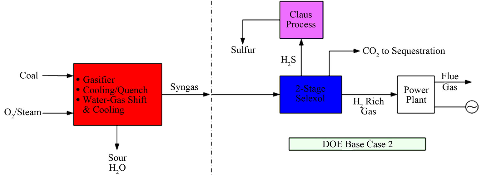
Figure 1. Overall process schematic for DOE Base Case 2 [2].
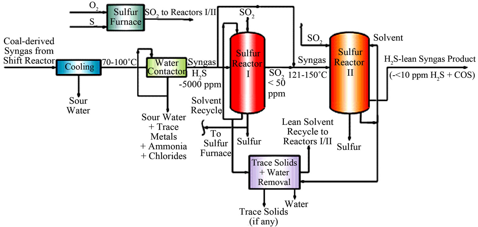
Figure 2. Two-stage sulfur-reactor concept for the UCSRP-HP technology.
tor fitted with high-surface area Sulzer SMVTM packing [4]. In this concept, the scrubbed syngas would be removed from the bottom of the unit for processing in the downstream sulfur-removal reactor. A slipstream of the circulating water would be withdrawn and filtered for the removal of water-insoluble solids. The filtrate will be treated in a stripper to remove 1) any dissolved ammonia/H2S for additional processing and 2) the water for processing in a wastewater treatment plant.
• H2S removal: H2S would be removed via the liquidphase Claus reaction (where H2S is reacted with SO2 at ~120˚C - 150˚C, in the presence of a liquid solvent (e.g., DGM: Diethylene Glycol Methyl Ether) mixed with a homogeneous catalyst (e.g., 3-pyridinemethnol), to form elemental sulfur plus water: 2H2S + SO2 = 3S + 2 H2O. The SO2 requirement for the reaction with H2S would be supplied by the combustion of about one-third of the sulfur product with oxygen. The reactor column temperature would be maintained at about 120˚C - 150˚C to ensure that the temperature is above the melting point (~120˚C) and below the polymerization temperature (~155˚C) of elemental sulfur. At these operating conditions, as liquid sulfur is essentially immiscible in DGM solvent and over twice as dense, it is removed as a separate product from the reactor column. In the GTI two-stage concept (schematic shown in Figure 2), the first-stage would be operated in the “excess-SO2 mode” whereas the second-stage would be operated in the “excessH2S mode” to enhance the reaction kinetics in forming sulfur (+water) in both of these reactors; here, “excess” is referred to as ~1% - 10% extra reactant (SO2 or H2S) than that required by the Claus reaction stoichiometry.
In the UCSRP-HP process for IGCC electric power generation, the H2S level in product syngas to a gas turbine would be limited to about 5 - 8 ppmv acceptable for modern gas turbines. For special applications involving the conversion of syngas to chemicals, hydrogen and clean gaseous/liquid fuels, the H2S level in product syngas would be reduced to below 50 ppbv. Details of the UCSRP-HP have been published previously [4,5]. Testing done at GTI has shown negligible chemical consumption (including catalyst) vs. typical costs of $300 - $1000 per ton sulfur removed required in competing processes. There is much less need for stainless steels in the process, and no apparent cut-off point in terms of sulfur handling at which Claus/SCOT becomes more economical. This process differs from liquid redox processes in important ways. There is no need for filtering a solid sulfur paste with attendant handling problems and loss of solvent. The sulfur quality can be as good as Claus sulfur due to the low solubility of the solvent in the liquid sulfur.
1.2.2. RTI Warm Syngas Cleanup Technology for the Removal of Trace Metals Components and H2S/COS
The RTI technology is currently being developed for the removal of heavy metals and H2S/COS from coal-derived syngas [6]. A key advantage of this technology relates to the use of relatively high operating temperature of ~455˚C. RTI, Eastman Chemicals and DOE have completed pilot plant demonstration of the technology; plans are currently underway for a larger scale demonstration (at ~50 MW-scale) at Tampa Electric’s (TECO) Polk Power Station in Polk County, FL. In this process, various proprietary adsorbents are used for the removal of trace metals. For the removal of sulfur compounds, multiple processing steps (consisting of HTDS and DSRP units) are used with solids recirculation, as outlined by the following key chemical reactions:
The HTDS (High Temperature Desulfurization) step has two key units, the absorber and regenerator.
• Absorber Unit (ZnO as the sorbent):
H2S + ZnO = ZnS + H2O (1)
• Sorbent Regenerator Unit:
ZnS + 1.5O2 = ZnO + SO2 (2)
The DSRP (Direct Sulfur Recovery Process) step also has two primary stages:
• Direct Sulfur Recovery (DSRP) Unit, Stage 1: The SO2 from the regenerator is reduced to elemental sulfur via the reactions
SO2 + 2CO = 2CO2 + S (3)
SO2 + 2H2 = 2H2O + S (4)
Direct Sulfur Recovery (DSRP) Unit, Stage 2: The tail gas from DSRP-1 is then sent to the DSRP-2 where the residual SO2 is hydrogenated to H2S via
SO2 + 3H2 = H2S + 2H2O (5)
The H2S-rich product from this step is cooled before recycling to the HTDS step.
1.2.3. GTI-Porogen Carbo-Lock Technology for the Separation of CO2
Gas Technology Institute (GTI) and PoroGen Corporation are jointly developing a novel hybrid membrane— absorption process for preand post-combustion CO2 capture (Carbo-LockTM process) [7]. The novel CarboLockTM process combines beneficial features of both absorption and membrane technologies for cost-effective separation and capture of CO2 from various emission sources. The Carbo-LockTM process is a hybrid of membrane and the conventional absorption processes. CO2- containing gas passes through small membrane tubes (hollow fibers with porous walls), while a CO2-selective solvent (e.g., an amine solution) flows on the shell side of the membrane tubes. CO2 passes through the nanoporous membrane and is absorbed in the selective solvent. The CO2-rich solvent can then be regenerated in a second membrane module operated in a reverse process. The Carbo-LockTM process uses a novel hollow fiber membrane technology patented by PoroGen. This novel membrane is made from a chemically and thermally stable commercial engineered polymer poly (ether ether ketone) or PEEK. The PEEK membrane contactor can provide a platform for solvent-based systems beyond conventional amines. The reduced size requirements translate to lower solvent inventories, less metal exposure to corrosive liquids, and lower overall footprint. The system operates at very low gas pressure drops, comparable to those achieved with very large diameter columns, and much lower than those of conventional membrane systems.
1.2.4. SRI/LANL Technology for the Separation of CO2
SRI International [8] and LANL (Los Alamos National Laboratory, [9]) are developing specific membranes from hollow fibers of a temperature-resistant (up to ~400˚C) and sulfur-tolerant polybenzimidazole (PBI) polymer with H2/CO2 selectivity of ~20 - 40. PBI material has a relatively high melting point that does not readily ignite, because of its exceptional thermal and chemical stability. As an example, the SRI membrane can be used to separate coal-derived syngas (at ~700 - 800 psig and ~250˚C) into two products: 1) a mixture of H2/steam plus a sweep-gas (e.g., N2 in IGCC applications), at ~250 - 450 psia and ~250˚C, for processing in a gas turbine, and 2) a CO2-rich stream (containing H2S plus other trace components) at about the feed-gas pressure and ~250˚C. Following removals of the sulfur and trace components, the CO2 stream can be processed for compression and sequestration.
1.2.5. Eltron Inc. Membrane Technology for the Separation of Hydrogen from CO2
Various R & D activities, including those by Eltron Inc., are continuing to develop effective membranes in separating H2 from CO2 in coal gasification applications. According to Eltron [10], their densemetal membrane can:
• Enable ~95% - 99% carbon capture under specific syngas cleanup scenarios.
• Maintain the product CO2 at near feed pressure to minimize compression cost for sequestration.
• Produce a relatively high-pressure H2 stream with over 90% hydrogen recovery and near 100% purity.
• Be ~10x less expensive than a typical Pd-membrane used for separating H2 and would have ~10x better performance.
Specific pilot plant demonstrations (at ~12 - 200 lb/ day scale) of the Eltron H2-membrane technology are currently under way with financial support from Eastman Chemicals and the US-DOE. Eltron’s R & D plans include Pre-Commercial Module (PCM; 5 - 10 tons/day H2) scale demonstrations.
2. Results and Discussions
2.1. Economic Potential for the UCSRP-HP Technology in Coal Gasification Applications with CO2 Capture
The economic potential of the UCSRP-HP process for IGCC-based electric power generation with CO2 capture (Case A: Table 1) in a nominal 550-MW plant was evaluated. Another power plant design case (Case-A-1) was also evaluated where the product syngas has a sulfur level below 50 ppbv as would be required for applications involving the production of various chemicals and liquid/gaseous fuels. The process design for Case A was based on the DOE Case 2 of “Cost and Performance Baseline for Fossil Energy Plants” [2]. Table 2 shows the contaminant targets for the two GTI cases. The UCSRP-HP cases were designed for the “Chemicals” specifications in both cases except for the H2S level. In the Case A, the H2S concentration in the feed gas to the gas turbine was ~8 ppm (vs. <50 ppb for Case A-1). The low level required the addition of a COS hydrolysis reactor and a guard-bed added to the IGCC case as noted later.
The UCSRP-HP Design Case A keeps the DOE Case 2 design up through the first heat exchanger (HP Steam) in the Gas Cooling, BFW Heating & Knockout block where the syngas feed is at ~53 bar and 232˚C. This is downstream of the Quench and Scrubber Section and the Water Gas Shift Reactors. The DOE Case 2 is rejoined at the feed to the CO2 removal section of the dual-stage SelexolTM unit. This design replaces or eliminates the Mercury Removal, H2S-removal section of the dual stage SelexolTM unit, the Claus Plant, and Hydrogenation Reactor and Gas Cooler Section. Schematic of the UCSRP-HP Base Case design (Case A) is shown in Figure 3. For Case A, the total SO2 emission from the IGCC power plant is about 34 lb/hr (115 tonne/y) vs. 56 lb/hr (190 tonne/y) specified in the DOE Case 2.
The syngas stream from the HP Steam heat exchanger is further cooled to 75˚C and then processed in a highpressure, co-current, down-flow Water Contactor unit to separate a large fraction of water present in the gas along with much of the NH3 and essentially all of the halogens and heavy metals, as sulfides or water-soluble salts. The sour gas feed enters Water Contactor, where it is contacted with a stream of circulating water. At the pressure, temperature, and water content of the syngas, the circulating water will have a steady-state content of NH3 and
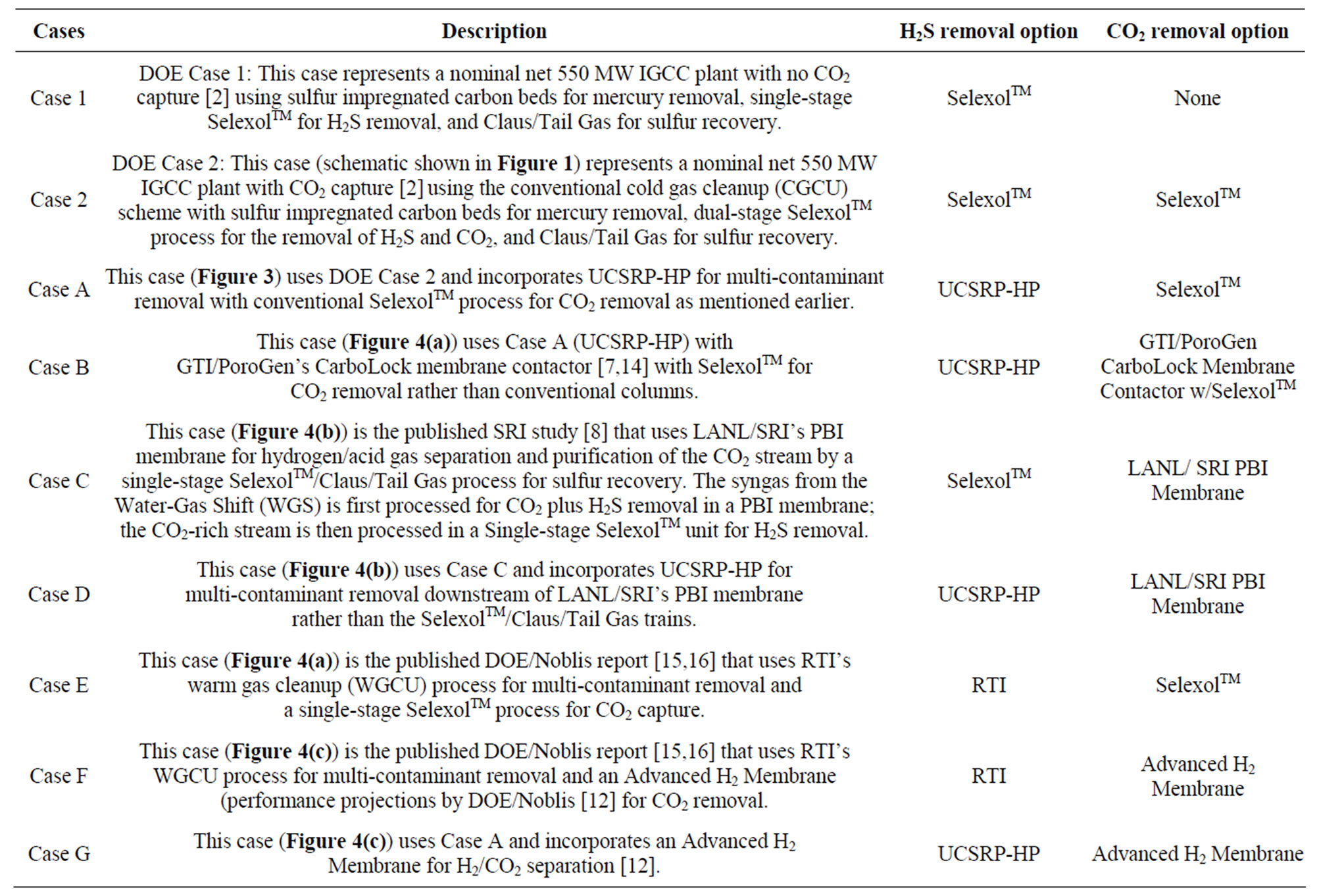
Table 1. Design cases and technologies used in the economic evaluations of various process pathways.
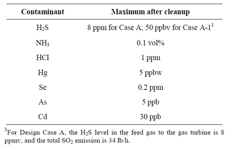
Table 2. Design targets for contaminants.
H2S. As a result, the HCl content of the feed gas will be absorbed very effectively to form highly soluble NH4Cl. A small but significant concentration of NH4HS will also be present in the liquid phase and the heavy metals As, Cd and Hg will be absorbed to form their respective, insoluble sulfides. Selenium will be present in the syngas as H2Se and will be absorbed to form highly soluble (NH4)2Se under these conditions. At the bottom of the scrub contactor, the water stream is withdrawn and circulated by pump back to the top after dissolved gases are flashed and returned to the feed gas stream. A slipstream of the water stream will be withdrawn for filtration and other treatments to remove the accumulated impurities, and then sent to the sour water stripper forwater treatment; the overhead sour gases from the stripper will be compressed and mixed with the syngas feed to the UCSRP reactor. Following this Water Contactor unit, the gas is preheated to about 120˚C prior to its processing in the UCSRP-HP reactor. The key objective for the removal of a large fraction of the water prior to the UCSRP-HP reactor in this specific design case is to minimize the cost of separation of water from DGM solvent used in the reactor. In future, other design options for the separation of water and DGM from the UCSRP reactor effluent(s) will be evaluated.
An Aspen Plus® simulation UCSRP-HP model was prepared to identify a co-current, down-flow contactor reactor design that is simple and less expensive to build compared to the original counter-current designs. A DGM slipstream is treated by hydro cyclones to remove any precipitated heavy metal salts that may not have been removed by the water filter. To be conservative, the design cases assume that some COS is formed within the UCSRP-HP reactor system. The sulfur is separated, filtered by a DURCO sulfur filter, and sent to a sulfur pit or
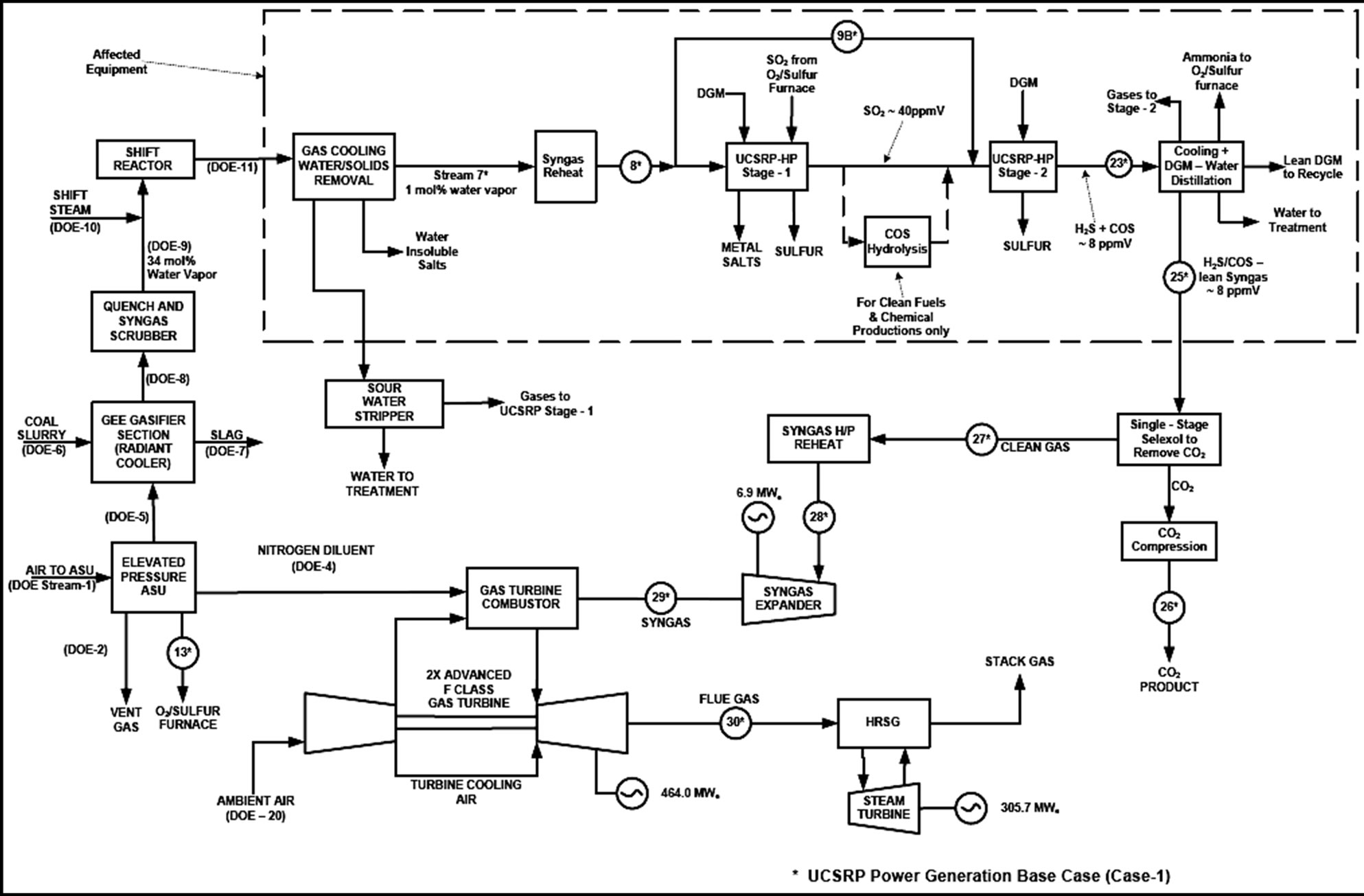
Figure 3. GTI UCSRP-HP Base Case (Design Case A) with CO2 capture (Total SO2 emission: 34 lb/hr and near zero for chemicals case, Case A-1).
to a commercial-design O2/sulfur submerged combustion furnace [11], as needed to generate the required liquid SO2 for reaction with H2S in the UCSRP-HP reactors. Ammonia from the DGM distillation unit is also fed to the sulfur furnace and converted to N2 and H2O as it passes through the furnace. The combustion gas raises steam in the boiler and then passes through the condenser, where liquid sulfur is collected. The wet SO2 gas then flows to a cooler, where liquid water, saturated with dissolved SO2, is condensed. The SO2 stream leaving the cooler is converted to liquid in another condenser, and then pressurized to the pressure of the reactor column by a pump.
The product syngas from the UCSRP-HP reactor is cooled to about 32˚C for 1) heat integration and 2) minimization of the loss of DGM solvent with the product syngas delivered to the IGCC plant. The cooled gas is sent to a high-pressure separator to recover DGM solvent that is processed in a distillation unit to remove the water 1) formed in the reactor due to the reaction of H2S and SO2, 2) present in the syngas feed to the reactors and 3) provide a lean DGM supply to the reactor. For the Chemicals case, to achieve the <50 ppb sulfur target, a COS hydrolysis unit is introduced in the UCSRP-HP reactor system to produce a syngas containing about 7.6 ppm H2S and 0.4 ppm COS. A zinc oxide guard-bed is also added downstream of the high-pressure separator to reduce the total sulfur level to <50 ppb in the effluent gas. If COS is shown not to form, the COS hydrolysis unit can be eliminated and the zinc oxide guard bed can be made smaller. To be conservative, there are three means to collect the heavy metals in the process. One is primarily by using water filters in the Water Removal unit. The other two backup means involve the use of DURCO liquid sulfur filter, and hydro cyclone/precipitation filters to process a slipstream of the recycle DGM solvent from the UCSRP-reactor. If further experimentation shows that all of the heavy metals are collected in the Water Removal unit as solid sulfides, the backup means can be eliminated. The sweet, cooled syngas is then transferred, as in the DOE Case 2 design, to the CO2 removal section of the dual-stage SelexolTM unit and the power island.
2.2. Process Economics
The methodology given in the referenced DOE report was followed to evaluate the UCSRP-HP process. Relative to the results for the DOE Case 2 that uses conventional cold gas cleanup scheme with SelexolTM/Claus/ Tail Gas-type H2S removal processes, the study shows
 (a)
(a)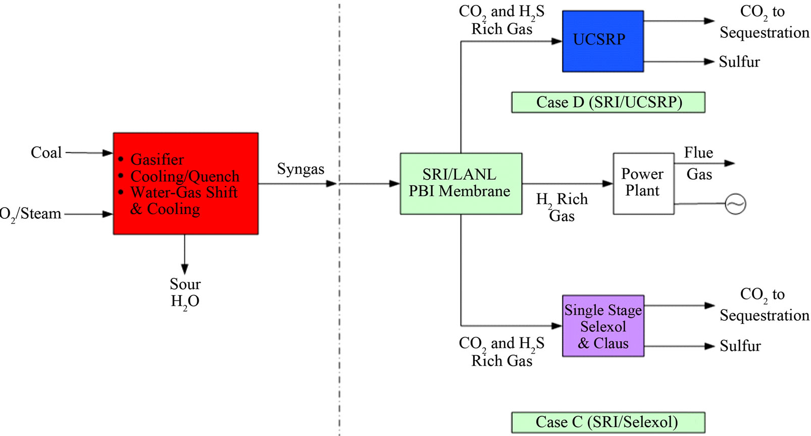 (b)
(b)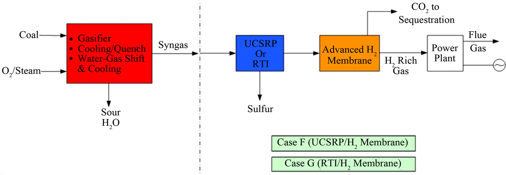 (c)
(c)
Figure 4. Overall process schematics: (a) Cases A, B, and E; (b) Cases C and D; (c) Cases F and G.
significant economic and environmental advantages (see Table 3) for the UCSRP-HP Base Case design:
• A net CAPEX savings of about $123 MM (Dec’06 dollars) based on the conservative design and ±30% cost estimate basis; key details on the comparative CAPEX data for the two designs are given in Table 4.
• The overall thermal efficiency (HHV basis) would increase from about 32.5% for the DOE Case 2 to about 33.5% for the UCSRP-HP design.
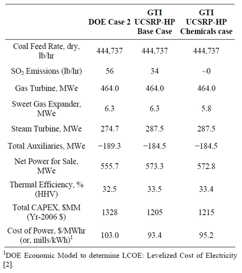
Table 3. Comparative COE data: DOE Case 2 vs. UCSRPHP.
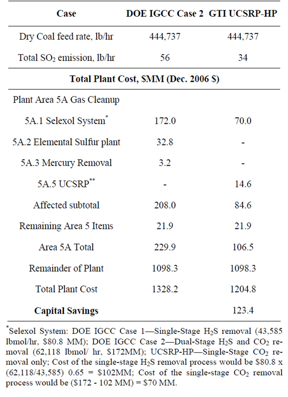
Table 4. Comparative data on CAPEX: DOE Case 2 vs. UCSRP-HP Base Case.
• An increase of about 17.6 MW (~3.2%) in net power sale.
• A reduction of about $9.60/MWhr (~9.3%) in the cost of electricity (COE) production with carbon capture, CO2 compression plus transport/storage/monitoring; and
• A reduction in total SO2 emission of about 22 lb/hr (74 tonne/y).
In addition, preparing the syngas for a Chemicals application that requires <50 ppb sulfur in the syngas would increase the COE by about $1.80/MWhr if the syngas was used for power generation in a near zero SO2 discharge IGCC plant.
Table 5 provides a comparison of the overall plant performance for the DOE Case 2 and the UCSRP-HP Base Case. The power production was set the same for both plants. The difference in saleable power is the difference in the auxiliary load. As seen here, the Claus Plant Tail Gas Recycle Compressor, first stage Selexol Unit Auxiliaries, and the Claus Plant/Tail Gas Unit Auxiliaries consumed 4751 kWe more than the UCSRP Units and Sulfur Furnace. This resulted in a modest efficiency increase for the UCSRP-HP from about 32.5% for the
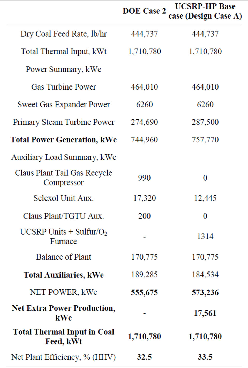
Table 5. Plant performance summary.
DOE Case 2 to about 33.5% for the UCSRP-HP Base Case design.
2.3. Economic Potential for the Integration of Key Membrane Technologies for the Removal of CO2 and H2 with the UCSRP-HP in IGCC Applications
The economic potential of integrating UCSRP-HP with 1) the LANL/SRI’s PBI (polybenzimidazole), high-temperature (~250˚C - 450˚C), polymeric CO2-removal membrane, 2) the GTI/PoroGen’s CarboLock Membrane for CO2 removal, and 3) an advanced H2-separation membrane that would meet specific year-2015 performance targets [12] assumed by DOE/Noblis LLC were also examined. For these economic evaluations, it is assumed that the CO2 product would need to meet the KinderMorgan specifications for existing commercial CO2 pipelines [13]. These cases were compared to the published data on RTI’s warm gas cleanup (WGC) process. The salient features of these various designs cases are summarized in Table 1. The schematic flow diagrams of the design cases A, B. C, D, E, F and G are shown in Figure 4.
The COE data for these integration options are compared in Table 6 with those derived from literature information. As shown in Table 6, both the RTI and the UCSRP-HP process integration options with an advanced hydrogen membrane appear to be quite promising in reducing the overall COE for future IGCC plants that would include CCUS.
Figure 5 shows how various developmental technologies affect the cost of electricity (see Table 1 for related design cases). The horizontal line marked “1” is the COE without carbon capture (Case 1). Point “2” is the base case for carbon capture using “conventional” capture technology (Case 2). The line 2-A-B-G represents incorporating UCSRP-HP for multi-contaminant removal with SelexolTM for CO2 removal (Case A), GTI/PoroGen’s CarboLock membrane contactor with SelexolTM rather than conventional columns for CO2 removal (Case B), and an Advanced H2 membrane for CO2 removal (Case G). Line 2-C-D represents incorporating the PBI membrane for H2/acid gas separation with purification of the CO2 stream by a single-stage SelexolTM/Claus/Tail Gas process for sulfur recovery (Case C) and UCSRP-HP for multi-contaminant removal (Case D). Line 2-E-F represents incorporating WGCU for multi-contaminant removal with a single-stage SelexolTM for CO2 removal (Case E) and an Advanced H2 membrane for CO2 removal (Case F). These cases show that UCSRP-HP can make a positive impact with new developmental technologies and become a viable alternative to competing multicomponent cleanup technologies.
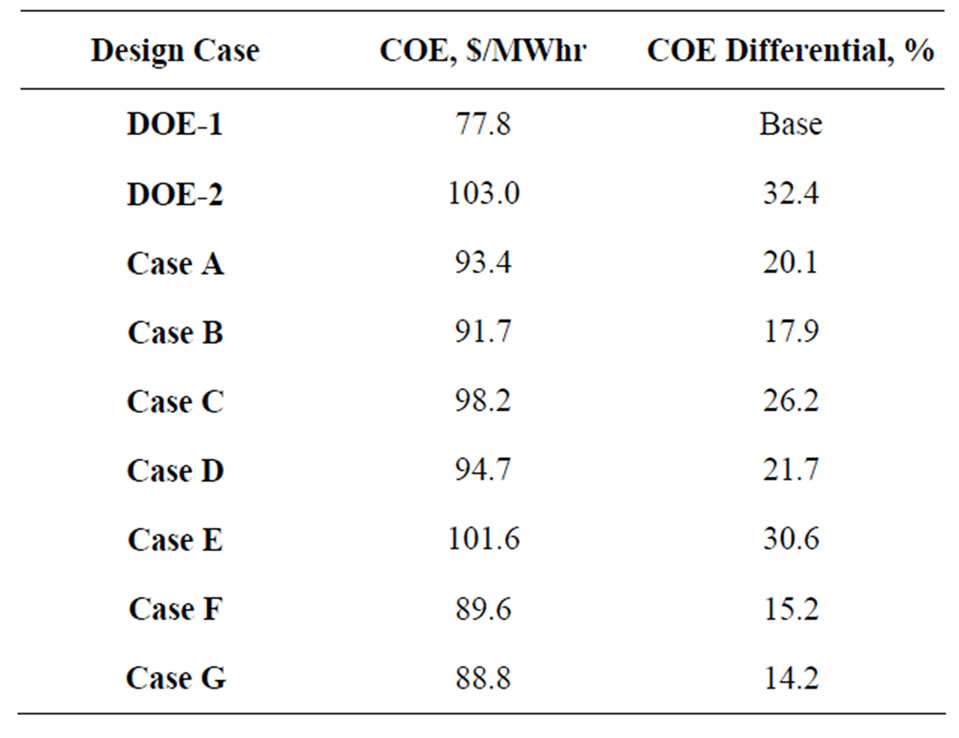
Table 6. Comparative data for COE (including CO2 capture, compression, transport, plus storage/monitoring).
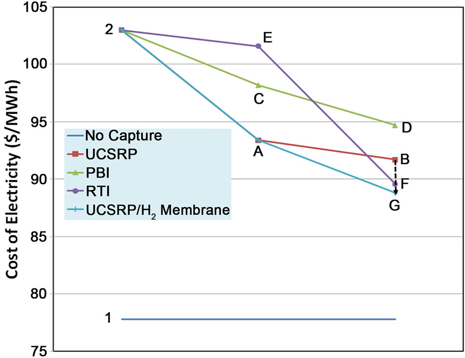
Figure 5. Comparative data for COE using multiple technology pathways and integrations.
3. Conclusions
The key conclusions of this study are:
• For economic evaluations of various novel technologies for sulfur removal and carbon capture in IGCC applications, estimates for COE would depend on overall thermal efficiency for power generation as well as the capital cost requirements.
○ As an example, the RTI WGCU technology for sulfur removal has demonstrated relatively high thermal efficiency; however, based on the DOE/ NETL estimates, the COE with carbon capture for Case E (RTI WGCU with single-stage SelexolTM for carbon capture) has been estimated at only ~1.4% lower relative to the DOE Case 2 (CGCU with two-stage SelexolTM).
○ In contrast, for Case A (using the UCSRP-HP technology for sulfur removal and the single-stage SelexolTM for carbon capture), a COE reduction of ~9.1% relative to the DOE Case 2 is estimated. This can be attributed to the significant savings in capital cost for the UCSRP-HP process due to its relative simplicity.
• As indicated in the Design Case G, integration of the UCSRP-HP process for sulfur removal with an Advanced H2 Membrane for H2/CO2 separation could lead to a COE value that would be only about 15% higher than DOE’s baseline cost projections (in DOE Case 1) for a no carbon capture IGCC plant.
○ The COE for Case G is similar (at about 15% increase relative to the no carbon capture case) to that estimated by DOE/Noblis for the Case F using the RTI process for sulfur removal and the advanced H2 Membrane process for CO2 removal.
• The UCSRP-HP technology may offer significant economic advantages over competing technologies in monetizing high-sulfur coals (e.g., Illinois basin coals).
4. Acknowledgements
This paper is based upon work supported by the Department of Energy National Energy Technology Laboratory under Award Number DE-FC26-05NT42458, and by the Illinois Clean Coal Institute with funds made available through the Office of Coal Development of the Illinois Department of Commerce and Economic Opportunity. The authors acknowledge the support and guidance of Jenny Tennant, DOE-NETL, Francois Botha and Debalina Dasgupta, ICCI, Dennis Leppin and Jim Wangerow, GTI, and Professor Scott Lynn, UC, Berkeley on this technology development.
REFERENCES
- BP Energy Outlook 2030, Slide 10, 2011. http://www.bp.com/liveassets/bp_internet/globalbp/globalbp_uk_english/reports_and_publications/statistical_energy_review_2008/STAGING/local_assets/2010_downloads/2030_energy_outlook_booklet.pdf
- Research and Development Solutions LLC., and Parsons Corp., “Cost and Performance Baseline for Fossil Energy Plants,” DOE/NETL-2007/1281, August 2007.
- H. S. Meyer, “Development of an Integrated Multi-Contaminant Removal Process Applied to Warm Syngas Cleanup for Coal-Based Advanced Gasification Systems,” Vol. 1, DOE Project # DE-FC26-05NT42458, Reporting Period: June 2005-November 30 2010.
- H. S. Meyer, “Integrated, Multi-Contaminant Removal Process for Syngas Cleanup—Phase 3,” ICCI Project Number 10/2A-1, 2010.
- A. Basu, H. S. Meyer, D. Leppin, J. Zhou and A. Makkuni, “UCSRP-A Flexible Sulfur Removal Process for Sweetening Natural Gas,” American Institute of Chemical Engineers Spring Meeting, Houston, 1-5 April 2012. http://www.aiche-fpd.org/listing/127.pdf
- http://www.rti.org/brochures/rti_adv_gasification.pdf
- S. Li, D. J. Rocha, S. J. Zhou, H. S. Meyer, B. Bikson and Y. Ding. “Post-Combustion CO2 Capture Using SuperHydrophobic, Polyether Ether Ketone, Hollow Fiber Membrane Contactors,” Journal of Membrane Science, Vol. 430, 2013, pp. 79-86. doi:10.1016/j.memsci.2012.12.001
- Krishnan, G., “Fabrication and Scale-Up of Polybenzimidazole (PBI) Membrane Based System for Pre-Combustion Based Capture of Carbon Dioxide,” 2011 NETL CO2 Capture Technology Meeting, Pittsburgh, 22-26 August 2011. http://www.netl.doe.gov/publications/proceedings/11/co2capture/presentations/5-Friday/26Aug11-Krishman-SRIPBI%20Membranes%20for%20Pre-Combustion%20Captur.pdf
- K. A. Berchtold, et al., “High Temperature PolymerBased Membrane Systems for Pre-Combustion Carbon Dioxide Capture,” NETL CO2 Capture Technical Meeting, Pittsburgh, 9-12 July 2012. http://www.netl.doe.gov/publications/proceedings/12/co2capture/presentations/4-Thursday/K%20Berchtold-LANLPolymer-based%20Membrane.pdf
- D. Jack, et al., “Scale-Up of Hydrogen Transport Membranes for Carbon Capture Applications,” Gasification Technology Conference, San Francisco, 9-12 October 2011. http://www.netl.doe.gov/technologies/coalpower/gasification/projects/adv-sep/42469/40JACK.pdf
- R. L. Schendel, “SO2-Generation Process Can Double Refinery Claus Unit Capacity,” The Oil and Gas Journal, 1993, pp. 63-66.
- D. Gray and J. Plunkett, “Personal Communication on Mass/Energy Balances and Cost Data for Advanced H2 Membrane,” 2010.
- K. Havens, “CO2 Transportation,” Indiana Center for Coal Technology Research, Slide 14, 2008. https://www.purdue.edu/discoverypark/energy/assets/pdfs/cctr/presentations/Havens-CCTR-June08.pdf
- S. J. Zhou, et al., “Hybrid Membrane/Absorption Process for Post-Combustion CO2 Capture,” NETL CO2 Capture Technology Meeting, Pittsburgh, 13-17 September 2010. http://www.netl.doe.gov/publications/proceedings/12/co2capture/presentations/1-Monday/J%20Zhou-GTI-Hybrid% 20Membrane%20Process.pdf
- DOE/NETL Report, “Current and Future Technologies for Gasification-Based Power Generation,” DOE/NETL Report 2009/1389, Vol. 2, 2009, pp. 3-17.
- DOE/NETL Report, “Current and Future Technologies: A Pathway Study Focused on Non-Carbon Capture Advanced Power Systems R & D using Bituminous Coal,” Vol. 1, DOE NETL-2008/1337, 2008, pp. 3-18.
NOTES
*Corresponding author.