E-Health Telecommunication Systems and Networks
Vol.1 No.1(2012), Article ID:18068,6 pages DOI:10.4236/etsn.2012.11002
Energy-Constrained Duty-Cycle Optimization for Wireless Implanted Communication Devices
Shenzhen Institutes of Advanced Technology, Chinese Academy of Sciences, Shenzhen, China
Email: zhao.xu@siat.ac.cn
Received March 20, 2012; revised March 25, 2012; accepted March 30, 2012
Keywords: Energy Minimization; Energy Consumption Model; Channel Model; Duty-Cycle; Optimization; Cross-Layer
ABSTRACT
Energy minimization is an important goal in wireless implanted communication devices. In this context, a cross-layer method is used to optimize parameters in different layers of OSI model, but, there are still several challenges affecting the optimization algorithm. The first point is the accurate energy model, and the second point is the suitable channel model exclude traditional free space channel model. In this paper, we establish a system level accurate energy consumption model and build a suitable channel model for implanted communication devices; analysis the energy-constrained duty cycle optimization with a cross-layer method. Simulation results reveal that adaptive duty cycle to minimize the energy consumption of the wireless implanted communication system is implemented based on accurate energy consumption model and channel model. Simulation results show a good performance on energy saving.
1. Introduction
The rapid developments of wireless communication and low power implanted techniques have opened up new frontiers in the race to conquer healthcare challenges. As wireless sensor networking technology comes into reality, it brings the revolution of E-Health application and new challenge of limited energy consumption, especially for implanted communication devices operating without battery replacement in a long time. For instance, capsule endoscopy needs to work continuously in human body for over 8 hours. Even, as to wireless pacemaker, it’ll operate inside the heart for many years. Therefore, the “battery gap” [1] makes energy saving become a very important consideration for the green E-Health application.
To minimizing the energy consumption, we should achieve an optimal joint design across all layers of the network protocol stack. The duty cycle is a very important parameter effecting the energy consumption in media access control (MAC) layer, but the effect by physical (PHY) layer also should be considered. In PHY layer, according to the Shannon formula, the energy should be saved by low data rate which means in a high duty cycle; but in MAC layer, there is contrary result that is longer sleep time (lower duty cycle) with higher data rate can minimize the energy consumption (Figure 1). So the relationship between the energy consumption and transfer time is not a monotonically function, and the minimum energy point achieved by the duty cycle optimization crossing layers.
Cross-layer optimization has been widely used in adhoc networks and wireless sensor networks. There is an extensively study on cross-layer optimization between data link layer and network layer. In [2], Jaejoon Cho et al. propose an energy-efficient routing method to enable nodes to reduce control traffic routing overhead using routing distance without big routing table. Safwat et al. present energy efficient scheme by successfully receiving a CTS or an ACK frame in MAC layer [3]. In [4], Jianwu Zhang et al. propose an optimal routing of minimizing the transmission energy without the link adaptation. Sichitiu et al. present node sleep mechanism based on MAC layer and routing [5]. For cross-layer optimization between PHY layer and MAC layer, Karvonen et al. present an optimization method on the code and sleep/ awake periods [6]. In [7], Huang et al. propose a crosslayer method for the joint design of scheduling and power control in wireless ad hoc networks by adaptive modulation with power control. Kwon et al. present a cross layer optimization by the power control in the physical layer, the ARQ control in the MAC layer, and the routing protocol in the network layer [8]. The works all above have achieved a joint optimization from different layers, but for wireless implanted communication devices, the analysis also should take accurate energy model and implanted channel model into account, not only based on an ideal fixed energy model and free space channel.
In this paper, we propose an energy-constrained duty cycle optimization for wireless implanted communication
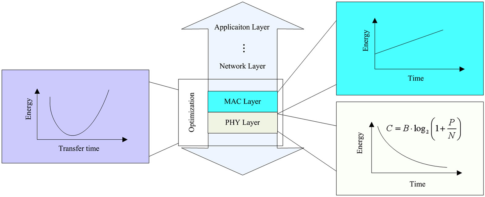
Figure 1. Duty cycle optimization crossing layers.
devices. With the consideration of the parameters affected by PHY and MAC layers, we implement an adaptive duty cycle optimization to minimize the energy consumption based on accurate energy model and channel model for wireless implanted communication devices.
2. System Model
2.1. Energy Model
A communication link connecting the transmitting path and the receiving path is considered. It is assumed that the analysis is done with MQAM modulation. In order to minimize the total energy consumption, all signal processing blocks at the transmitter and the receiver need to be considered in the optimization model. It is also assumed that no complicated signal processing techniques such as multiuser detection or iterative decoding are used. The power consumption in these parts are quite small [9] compared with the power consumption in the RF circuitry block, which is closely related to the carrier frequency. Thus, in this paper, these blocks (e.g., source coding, pulse-shaping, and digital modulation) are neglected to simplify the model. The resulting signal paths on the transmitter and receiver sides are shown in Figure 2, where it is seen that on the transmitter side, the baseband signal is converted to an analog signal by the digital-to-analog converter (DAC), then filtered by the reconstruction filter and modulated by the mixer, then amplified by the power amplifier (PA), and finally filtered again and transmitted to the wireless channel. On the receiver side, the RF signal is first filtered by the RF band selected filter and amplified by the low noise amplifier (LNA), then down converted by the mixer, and amplified again by the baseband amplifier, then filtered again before going through the analog-to-digital converter (ADC)
to convert back to a digital signal. Although this model is based on a generic low-IF transceiver structure, the framework can be easily modified to analyze other architectures as well.
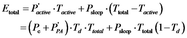
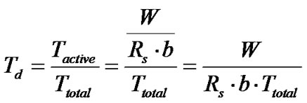
It is assumed that an implanted device has W bits to transmit with a deadline T. The transceiver spends time Tactive ≤ T to communicate these bits, then Td is a parameter to optimize which is equal to Td = Tactive/Tsleep, and then returns to the sleep mode where all the circuits in the signal path are shut down for energy saving. In wireless communication system, the full-duplex transceiver works in two modes (active and sleep mode). Correspondingly, the total energy consumption Etotal required to send L bits also consists of two components.
 (1)
(1)
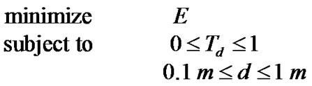
Then, the energy-constrained modulation problem can be modeled as
 (2)
(2)
where it is seen that the task is to find the most efficient way to choose the transmission duty cycle under the given system constraints so that the total energy consumption is minimized. For the second constraint, the transmit distance (only 0.1 m to 1 m) is very short for implanted device, in this paper, we choose d0 = 0.5 cm as the reference distance. From the resulting optimal Td, the duty cycle optimization for energy efficiency can be obtained.
First of all, it is essential to analysis the energy consumption of the RF front end because of the largest share. We have established accurate model for the main component and find out the key parameters related to the energy minimizing.
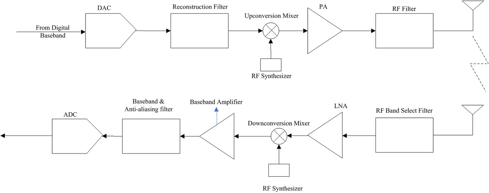
Figure 2. Transceiver circuit blocks of the analog signal chain.
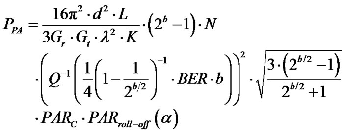
Energy consumption for PA is dominant in all components of RF front-end and the power consumption model of the PA is given by [11]
 (3)
(3)
where BER is the bit error rate, PAR is the peak-to-average ratio, N, b, Gt, Gr, are the noise power, modulation level, transmitter and receiver antenna gains respectively. And K is a constant, L is the system loss factor not related to propagation, λ is the carrier wavelength.
According to [13], the medical devices can operate on the medical implanted communication band (from 402 MHz to 405 MHz). Most of medical sensors have a maximum current consumption less than 6 mA and the supply voltage vary from 1.8 V to 3.5 V. We assume Pe equal to 13 mW in our analysis. Consider the modulation and denote, where Rs is the symbol rate, in hertz. Then, the active energy consumption per bit for the RF frontend for all modulation levels b is given by
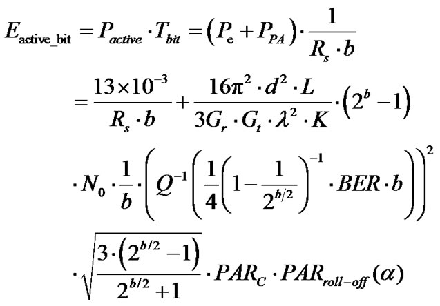 (4)
(4)
2.2. Channel Models for Implanted Sensor Devices
For implanted channel model, the traditional system design is established with normal free space channel. Since the impact of human tissue on signal transmission is serious, we must evaluate the impacts of human tissue and build an accurate channel model suitable for implanted devices.
Many theoretical and measurement-based studies presented in literature have shown that the average received signal decreases logarithmically with distance. Therefore, the average path loss for a distance between transmitter and receiver is expressed as
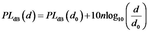 (5)
(5)
where, n is the path loss exponent that indicates the rate at which the path loss increases with distance and d0 is a reference distance set in measurement, PLdB(d0) is the reference path loss in dB corresponding to the reference distance d0, and we don’t consider the Gaussian noise the path loss model.
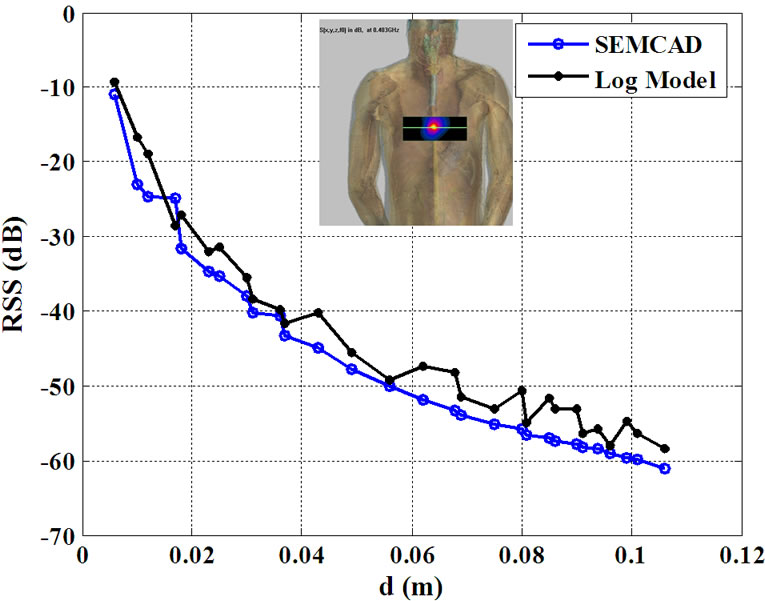
SEMCAD is used to analysis the path loss exponent implanted communication model at both chest and abdomen (Figure 3), and we can get the average value of pass loss exponent as shown in Table 1.
2.3. Energy Model for Implanted Devices
From above analysis, we can see that the tissue impacts the signal transmission severely. So, we have to consider the tissue’s effect before optimization algorithm.
According to [14], the path loss for free space model can be expressed as
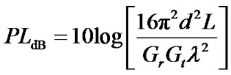 (6)
(6)
So
 (a) Cheat
 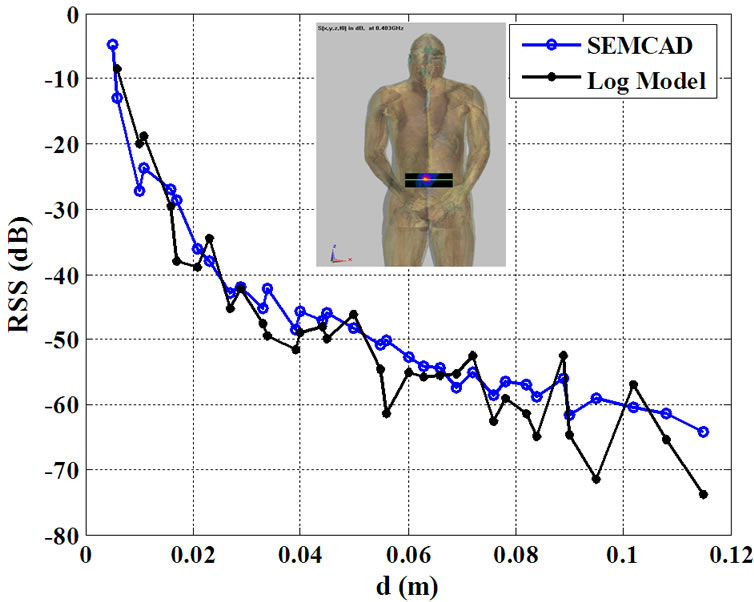 (b) Abdomen
Figure 3. Path loss model for implanted sensor nodes.
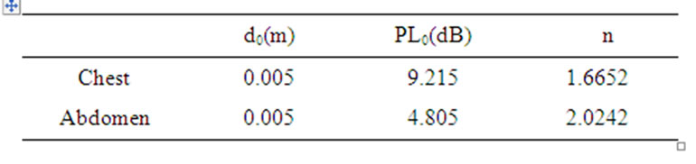
Table 1. Modeling parameters for implanted channel.
 (7)
(7)
But for the implanted communication channel, according to equation (5), we can get
 (8)
(8)
Since equation (7) and equation (8) are used to express the path loss of free space communication model and implanted communication model respectively, we can replace the left part of equation (7) with the left part of equation (8) when calculate the power consumption with the additional consideration of the effect of human tissue, and update the power consumption of the class A linear PA with MQAM modulations derived by
 (9)
(9)
Then, the total energy consumption per bit can be expressed by
 (10)
(10)
3. Optimization Algorithm
In this section, we consider a duty cycle optimization method for energy-constrained communication system. We present the duty cycle optimization  in MAC layer by the optimal parameters in PHY layer for minimizing the energy consumption. The sleep mode is equal to Tsleep=Ttotal – Tactive, and the power consumption of the RF front-end in sleep mode can be fixed at 0.5 mw.
The total energy consumption can be expressed as
 (11)
(11)
The duty cycle Td can be expressed as
 (12)
(12)
Thus, b is
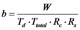 (13)
(13)
 is a function of d, and
 (14)
(14)
When communication device works on a short active timeslot, the data stream must finish the transmission in a short timeslot, which means the symbol rate should be large or the modulation level should be selected for a large one in PHY layer. It is hard to decide when the active/sleep mode should be changed. The optimal duty cycle is the value which can directly show the suitable point when the energy consumption is minimal. Therefore,  is the duty cycle that minimize Etotal, and then it can be expressed as
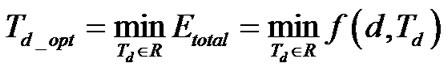 (15)
(15)
The number of elements in the set R is practically finite, for instance .
.
4. Cross-layer Optimization Design for Implanted Wireless Communication System
Figure 4 shows the effect of the duty cycle with different values of the distance d for Total energy consumption of the implanted communication device. For larger distance, the energy consumption will increase by fixed . When distance is fixed, there is a duty cycle which could minimize total energy consumption, that is,
 .
.
According to Figure 4, we will have an energyconstrained duty cycle optimization for implanted BSN communication devices. For instance, if assume that d = 0.2 m, we can get the minimum energy consumption when  is equal to 0.2, which means that the ratio of active time to sleep time is 1:4. According to (11), if duty cycle
  = 0.2 is chosen, the total energy consumption Etotal = 2.8 mJ.
5. Conclusion
In this paper, an energy-constrained duty-cycle optimization for a wireless transceiver of implanted devices is proposed. Two important models have been studied: a system level energy model for the RF front-end and a channel model for implanted communication. The effects of signal bandwidth, PAR, symbol rate, modulation level, transmission distance, duty-cycle, and the implanted communication path loss are considered. With a cross-layer method, we got the optimal duty-cycle to minimize the total energy consumption. For such a system, tradeoffs between the transfer time and the energy consumption and communication quality are presented. Future work includes adding the effect of error coding on the energy model.
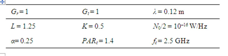
Table 2. System parameter values.

Figure 4. Total energy consumption versus duty-cycle with different distance.
6. Acknowledgements
This work was supported in part by the National S & T Major Project of China (Grant No. 2011ZX03005-001- 04), the Guangdong Innovation Research Team Fund for Low-cost Healthcare Technologies (GIRTF-LCHT).
REFERENCES
- K. Lahiri, A. Raghunathan, S. Dey and D. Panigrahi, “Battery-Driven System Design: A New Frontier in Low Power Design,” Proceedings of 7th Asia and South Pacific and the 15th International Conference on VLSI Design, Bangalore, 7-11 January 2002, pp. 261-267.
- J. Cho, S. Kim, H. Nam and S. An, “An Energy-Efficient Mechanism Using CLMAC Protocol for Wireless Sensor Networks,” Third International Conference on Networking and Services, Athens, 19-25 June 2007, p. 3.
- A. Safwat, H. Hassanein and H. Mouftah, “ECPS and E2LA: New Paradigms for Energy Efficiency in Wireless Ad Hoc and Sensor Networks,” Global Telecommunications Conference, Canada, 1-5 December 2003, pp. 3547- 3552.
- J.-W. Zhang, Y.-F. Chen and J.-J. Zhang, “Joint Routing, MAC, and Link Layer Optimization in Virtual MIMO Sensor Networks,” IET International Conference on Wireless Mobile and Multimedia Networks Proceedings, Hangzhou, 6-9 November, 2006, p. 26.
- M. L. Sichitiu, “Cross-Layer Scheduling for Power Efficiency in Wireless Sensor Networks,” Twenty-third Annual Joint Conference of the IEEE Computer and Communications Societies, Hong Kong, 7-11 March 2004, pp. 1740-1750.
- H. Karvonen, C. Pomalaza-Raez and M. Hamalainen, “Cross-Layer Energy Efficiency of FEC Coding in UWB Sensor Networks,” IEEE International Conference on Ultra-Wideband, Waltham, 24-27 September 2006, pp. 357-362. doi:10.1109/ICU.2006.281576
- W. L. Huang and K. B. Letaief, “Cross-Layer Scheduling and Power Control Combined with Adaptive Modulation for Wireless Ad Hoc Networks,” IEEE Transactions on Communications, Vol. 55, No. 4, 2007, pp. 728-739. doi:10.1109/TCOMM.2007.894093
- H. Kwon, T. H. Kim, S. Choi and B. G. Lee, “A CrossLayer Strategy for Energy-Efficient Reliable Delivery in Wireless Sensor Networks,” IEEE Transactions on Wireless Communications, Vol. 5, No. 12, 2006, pp. 3689- 3699. doi:10.1109/TWC.2006.256992
- M. Srivatsava, “Power-Aware Communication Systems,” Kluwer Academic, Boston, 2002.
- H. C. Liu, J. S. Min and H. Samueli, “A Low-Power Baseband Receiver IC for Frequency-Hopped Spread Spectrum Communications,” IEEE Journal of Solid-State Circuits, Vol. 31, No. 3, 1996, pp. 384-394. doi:10.1109/4.494200
- Y. Li, B. Bakkaloglu and C. Chakrabarti, “A System Level Energy Model and Energy-Quality Evaluation for Integrated Transceiver Front-Ends,” IEEE Transactions on Very Large Scale Integration Systems, Vol. 15, No. 1, 2007, pp. 90-102.
- J.-Q. Zhai, H.-S. Zhang, Y. Li and Y.-W. Zhang, “Energy Efficient RF Front-Ends Architecture Design for Wireless Sensor Networks,” Proceedings of the Networks Security Wireless Communications and Trusted Computing, Wuhan, 24-25 April 2010, pp. 236-239.
- P. D. Bradley. “Implantable Ultralow-Power Radio Chip Facilitates In-Body Communications,” 2007. http://mobiledevdesign.com/hardware_news/radio_implantable_radio_chip/
- T. S. Rappaport, “Wireless Communications: Principles and Practice,” 2nd Edition, Publishing House of Electronics Industry, Beijing, 2008.