Open Journal of Fluid Dynamics
Vol.07 No.03(2017), Article ID:78994,12 pages
10.4236/ojfd.2017.73018
Numerical Simulation of Interaction between Supersonic Flow and Backward Inclined Jets Surrounded by Porous Cavity
Nao Kuniyoshi1, Minoru Yaga2
1Department of Marine Electronics and Mechanical Engineering, Tokyo University of Marine Science and Technology, Koto-ku, Japan
2Department of Mechanical Systems Engineering, University of the Ryukyus, Nishihara, Japan

Copyright © 2017 by authors and Scientific Research Publishing Inc.
This work is licensed under the Creative Commons Attribution International License (CC BY 4.0).
http://creativecommons.org/licenses/by/4.0/


Received: July 25, 2017; Accepted: September 9, 2017; Published: September 12, 2017
ABSTRACT
As one of supersonic mixing techniques, a supersonic mixing technique using a cavity and a porous wall has been proposed. The cavity and the porous wall generate the low speed region in the cavity, which enhances mixing the main flow with the jets. In this study, numerical simulations were conducted to clarify the effects of backward inclined jets on the mixing technique using a porous wall and a cavity. In the numerical simulations, three patterns of jet injections which combined normal jets with backward inclined jets were studied. As a result, the combination of a backward inclined jet and a normal jet generates the suction flow behind the backward inclined jet, which is useful for making the injected jets flow into the cavity. In addition, the introduction of backward inclined jets reduces the total pressure loss. On the other hand, the mass flow rate through the porous holes decreases with increase in the number of the backward inclined jets.
Keywords:
Supersonic Mixing, Cavity, Porous Wall, Backward Inclined Jet

1. Introduction
Supersonic mixing enhancement techniques are important for scramjet engines. Air passes through a scramjet engine at supersonic speed, so the lack of time for mixing fuel with air becomes a problem. Moreover, the compressibility effect reduces a growth rate of mixing layers. Therefore, effective supersonic mixing enhancement techniques are required. Supersonic mixing techniques can be applied not only to scramjet engines but also to chemical oxygen iodine lasers [1] . Many researchers have investigated supersonic mixing techniques such as techniques using streamwise vortexes, and techniques using cavities. Gerlinger et al. [2] investigated a lobed strut injector to create counter-rotating streamwise vortices. It is revealed that this technique shortens the length to achieve a mixing. Kubo et al. [3] experimentally studied the effects of some types of hypermixer injectors with an unswept and a swept. As a result, it is found that the swept type injector shows good performance when the streamwise vortices are not generated sufficiently. Das et al. [4] numerically investigated supersonic combustion with a wall mounted cavity. As a result, a trailing edge injection shows good performance. Ukai et al. [5] conducted experimental investigation of a rectangular open cavity with upstream dual injectors. It is found that the distance between the jets affects the flow from the mainstream to the cavity and the long distance between the jets shows good characteristics within the cavity.
In addition to these supersonic mixing techniques, the authors have investigated a technique using a cavity and a porous wall, as shown in Figure 1. The cavity is attached to the lower wall and a porous wall is located between the main duct and the cavity. Then a jet is injected on the porous wall into the main flow, which generates a bow shock wave. The pressure difference across the bow shock wave generates flows between the main flow and the cavity flow, as shown in Figure 1. Therefore, the supersonic main flow and the jet flow into the cavity. The cavity flow is slower than the main flow. Therefore, it can solve the problem of the lack of time for mixing the jet with the main flow. Moreover, the introduction of a porous wall to a cavity is considered to reduce the total pressure loss caused by a cavity.
In the mixing technique using a porous wall and a cavity, the increase in the static pressure due to the bow shock waves generated by jets on the porous wall generates the suction flows and the blowing flows through the porous wall. Therefore, the flow between the main flow and the cavity flow is considered to be affected by the number of jets on the porous wall, jet arrangements, and jet angles. The effects of normal jets on the flow field around a porous cavity have been studied [6] [7] . However, the effects of backward inclined jets on the flow around a porous cavity have been little investigated. Therefore, it is important for the mixing technique to clarify the effects of backward inclined jets on the flow
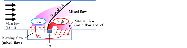
Figure 1. Proposed mixing enhancement technique [6] [7] .
around a porous cavity.
In the present study, numerical simulations were conducted to investigate the effects of backward inclined jets on the flow field around a porous cavity. In the simulations, three jets were aligned on a porous wall in the streamwise direction and each jet adopts an angle of 45 degrees or 90 degrees to the streamwise direction. In this paper, the difference between backward inclined jets and normal jets, and the effect of the combination of a backward inclined jet and a normal jet are presented.
2. Numerical Procedure
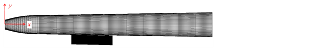
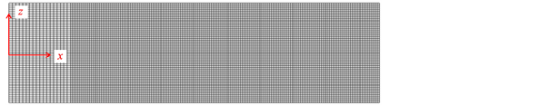
Numerical simulations were conducted to clarify the effects of backward inclined jets on the flow around a cavity. Three dimensional compressible Navier-Stokes equations are solved by the finite volume method in a curvilinear generalized coordinate. The inviscid flux is evaluated by the AUSMDV scheme. In addition, the third order MUSCL approach with the van Albada limiter is adopted. The viscous flux is evaluated by the central differencing technique. The Baldwin-Lomax model is used as the turbulence model. The forward Euler method is used for the time integration. Figure 2 shows the grid structure of the main duct and the cavity. The streamwise length of the main duct is 21.9 h*, where h* denotes the throat height. The cavity is located between x/h* = 7.0 and 11.37. The depth of the cavity is h*. The holes of the porous wall are distributed regularly. The number of the holes along the streamwise direction and the spanwise direction are eleven and fifteen, respectively. The porosity of the porous wall is 0.25. The grid numbers of the main duct along the x, y, and z directions are 201, 41, and 62, respectively. The grid becomes fine approaching the upper wall and the lower wall. The upper wall and the lower wall of the main duct have diverging angle of 1 degree in order to avoid a choking at the exit and to reduce the oscillation of the main flow and the shock waves. The grid numbers of the
 (a)
(a)
 (b)
(b)
Figure 2. Grid structure. (a) Side view of the calculation domain; (b) Top view of the calculation domain.
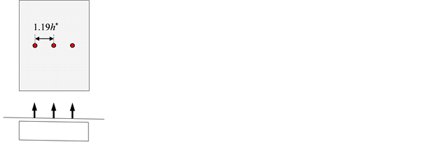
cavity along the x, y, and z directions are 46, 61, and 62, respectively. The boundary condition of the inlet is choking condition. The 1/7 power law is applied to the velocity profile at the inlet. The upper wall and the lower wall adopt Non-slip conditions. The side walls adopt slip conditions. The exit condition of the main duct depends on the Mach number at the exit. If the flow at the exit is supersonic, the boundary condition is extrapolated from the inner properties. On the other hand, the static pressure is fixed at the atmospheric pressure if the flow is subsonic at the exit. The flows through the porous holes are calculated by an empirical formula proposed by Doerffer and Bohning [8] . Figure 3 shows jet arrangements and jet angles. The simulations were conducted for three cases. For Case 1, the three jets are aligned streamwise direction and all the jets are injected normally. For Case 2, the first jet adopts the 45 degrees to the streamwise direction and the others are normal jets. For Case 3, the first jet and the second jet are backward inclined jets. The third jet is a normal jet. The pressure ratio p0/pb of the main flow is 10.0, where the pressure ratio p0/pb is defined as the ratio of the stagnation pressure p0 of the main flow at the center of the inlet to the back pressure pb. The pressure ratio pj0/pb of jets is 5.0, where the pressure ratio pj0/pb of jets is defined as the ratio of the stagnation pressure pj0 at the inlet of the jet to the back pressure pb. The calculations were continued until flow field became steady state. The time averages of the numerical simulations were calculated to reduce effects of small fluctuations of the flow field.
3. Results and Discussion
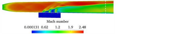
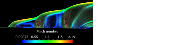
Figure 4 shows the colored images of Mach number in the x-y plane at z/h* = 0. For Case 1, three bow shock waves are generated by the jets. There are the differences between the penetration heights of the jets because the second jet and the third jet are injected into the dead air regions of their upstream jets. For Case 2 and Case 3, the backward inclined jets generate small dead air regions. Moreover, the backward inclined jets generate the weak bow shock waves compared with the normal jets. Therefore, the blockage effect of the backward inclined jets
 (a)
(a)
 (b)
(b)
 (c)
(c)
Figure 3. Jet arrangements. (a) Case 1; (b) Case 2; (c) Case 3.
 (a)
(a)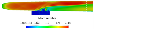 (b)
(b)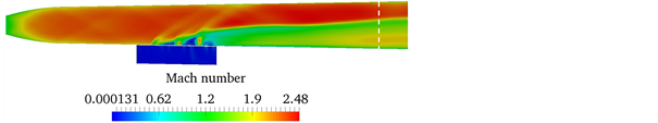 (c)
(c)
Figure 4. Colored images of Mach number in the x-y plane at z/h* = 0. (a) Case 1; (b) Case 2; (c) Case 3.
is smaller than that of the normal jets.
Figure 5 shows the colored images of Mach number in the y-z plane at x/h* = 20. The positions are indicated by the dashed lines in Figure 4. In Figure 5(a), the left side and the right side are a result for Case 1 and a result for Case 2, respectively. In Figure 5(b), the left side and the right side are a result for Case 1 and a result for Case 3, respectively. The penetration height of the jets for Case 1 is highest of all the cases. The second jet and the third jet are injected into the dead air region of its upstream jet, and the penetration heights of the jets is considered to become high as the dead air region is large. As discussed above, the normal jets generate the large dead air regions compared with the backward inclined jets. Therefore, the penetration height of the jets for Case 1 becomes the highest of three cases. High penetration height is effective in mixing enhancement. Therefore, Case 1 shows good performance in terms of jet penetration height.
Figure 6 indicates the static pressure distributions along the centerline on the upper wall. The static pressures increase from x/h* = 10 because of the bow shock waves. The static pressure peak indicated by A for Case 1 is high compared with those for Case 2 and Case 3, which indicates that the backward inclined jets generate weak bow shock waves. On the other hand, the static pressure peak indicated by B for Case 1 is almost the same as those for Case 2 and
 (a)
(a)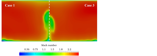 (b)
(b)
Figure 5. Colored images of Mach number in the y-z plane at x/h* = 20. (a) Case 1 and Case 2; (b) Case 1 and Case 3.
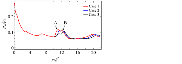
Figure 6. Static pressure distributions along the centerline on the upper wall.
Case 3.
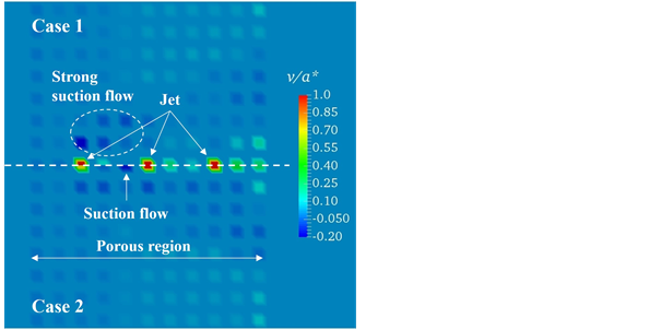
Figure 7 shows the colored images of the velocity component v in the y direction on the lower wall. The velocity is normalized by the sonic speed a* at the inlet. In Figure 7(a), the top and the bottom show the results for Case 1 and Case
 (a)
(a)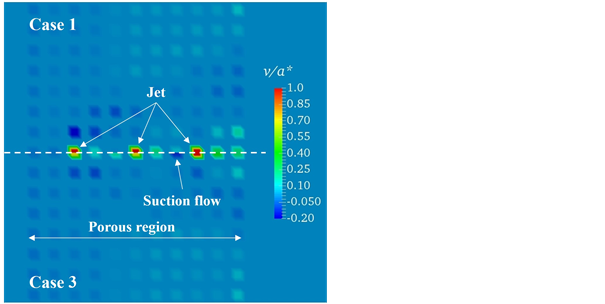 (b)
(b)
Figure 7. Colored images of the velocity component in the y direction on the lower wall (porous wall). (a) Case 1 and Case 2; (b) Case 1 and Case 3.
2, respectively. For Case 1, strong suction flows appear around the first jet because the first normal jet generates the strong bow shock wave as shown in Figure 6. For Case 1, blowing flows from the cavity are observed behind all the jets, and a large blowing flow region appears behind the third jet. These blowing flow regions correspond to the dead air regions of the jets. For Case 2, the suction flows around the first jet become weak compared with that for Case 1. For Case 2, the first jet is a backward inclined jet which generates the weak bow shock wave. Therefore, the suction flows around the first jet become weak. On the other hand, suction flow appears between the first jet and the second jet. For Case 1, the suction flow behind the jet is not confirmed. In Figure 7(b), the top and the bottom show the results for Case 1 and Case 3, respectively. For Case 3, the suction flows around the first jet also become weaker than those for Case 1 because the first bow shock wave generated by the backward inclined jet is weak. A suction flow is observed behind the second jet, which is not observed for Case 1. The suction flows behind jets are observed only between the backward inclined jet and the normal jet for Case 2 and Case 3. It is not observed between the normal jets and between the backward inclined jets. It is revealed that the combination of a backward inclined jet and a normal jet has an important role in generating suction flows behind a jet. Suction flows behind jets are very important for our mixing technique to make the jets flow into the cavity. Therefore, the combination of a backward inclined jet and a normal jet is very useful for achieving mixing the jets with the main flow in the cavity.
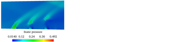
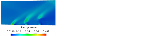
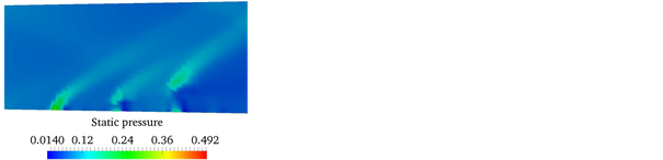
The colored images of the static pressure in the x-y plane at z/h* = 0 are shown in Figure 8. For Case 1, the first bow shock wave is the strongest of the three bow shock waves. For Case 2, the second bow shock wave approaches the lower wall, and it becomes stronger than that for Case 1. On the other hand, the first bow shock wave is weaker than that for Case 1. For Case 3, the first and the second backward inclined jets generate weak bow shock waves. The distance between the lower wall and the third bow shock wave is shorter than those for the other cases. Moreover, third bow shock wave is strong. For Case 2 and Case 3, these high pressure regions approaching the lower wall are considered to affect the suction flow regions between a backward inclined jet and a normal jet
 (a)
(a)
 (b)
(b)
 (c)
(c)
Figure 8. Colored images of static pressure in the x-y plane at z/h* = 0. (a) Case 1; (b) Case 2; (c) Case 3.
shown in Figure 7. For Case 2 and Case 3, the high pressure regions approaching the lower wall are considered to affect the pressure distribution on the lower wall. To clarify the effect of backward inclined jets on static pressure distribution on the lower wall, the static pressure distributions along the centerline on the lower wall are shown in Figure 9. The dashed lines indicate the jet positions in Figure 9. For Case 1, the static pressure increases in front of the first jet. The increase in the static pressure around the first jet occurs more upstream than those for Case 1 and Case 2. In addition, the static pressure peak at the first jet for Case 1 is smallest of the three cases. The different tendency for Case 1 is considered to be caused by the strong interaction between the first normal jet for Case 1 and the main flow. For Case 2 and Case 3, the first jets are backward inclined jets. Therefore, the two cases show the same tendencies around the first jet. The static pressure between the first jet and the second jet for Case 2 becomes larger than that for Case 1. However, the increase in the static pressure is small. The static pressure between the second jet and the third jet for Case 3 is almost same as that for Case 1. Therefore, the effect of the combination of a backward inclined jet and a normal on the static pressure on the lower wall is small.
Figure 10 shows the stream lines around the porous cavity. The Color indicates Mach number. For Case 2 and Case 3, the backward inclined jets generate more complicated flow field compared with normal jets. In addition, a small vortex is observed behind the first jet for Case 2. The backward inclined jets have the streamwise component of velocity and generate small dead air region, which makes differences between the dead air region of the normal jets and the dead air region of the backward inclined jets.
Figure 11 shows mass flow rates m through the porous wall. The mass flow rates are the sums of the blowing flows and the suction flows through the porous wall, which are normalized by the mass flow rate mCase1 for Case 1. Figure 11 shows that the mass flow rate decreases as the number of backward inclined jets increases, because backward inclined jets weaken the flows through the porous holes as shown in Figure 7. As mentioned above, the introduction of backward inclined jets realizes desirable suction flow regions. However, it reduces the mass
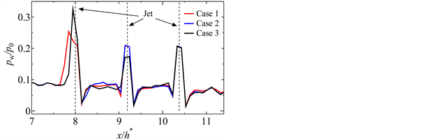
Figure 9. Static pressure distributions along the centerline on the lower wall.
 (a)
(a)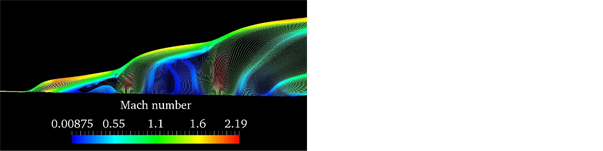 (b)
(b)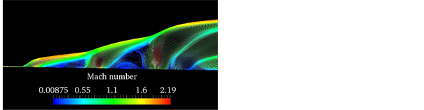 (c)
(c)
Figure 10. Stream lines around the porous cavity in the x-y plane at z/h* = 0. (a) Case 1; (b) Case 2; (c) Case 3.
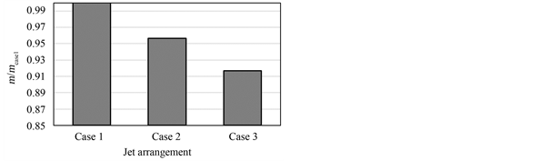
Figure 11. Mass flow rates through the porous wall.
flow rate through the porous holes. Therefore, methods to increase suction flow are needed for achieving more effective mixing.
Figure 12 shows total pressure distributions. The total pressures are calculated as mass weighted average of the total pressure in the y-z plane. They were
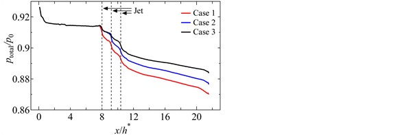
Figure 12. Total pressure distributions.
normalized by p0. The dashed lines indicate the jet positions. The large total pressure losses are caused by the jets. The normal jets cause large total pressure loss compared with the backward inclined jets. Therefore, the total pressure loss for Case 1 is the largest of the three cases. Reducing total pressure losses is important for effective mixing techniques as well as enhancing the mixing jets and a main flow. Therefore, backward inclined jets are effective in the mixing technique in terms of reducing total pressure loss.
4. Conclusions
The effects of backward inclined jets on the mixing technique using a porous wall and a cavity were numerically studied. Moreover, the difference between backward inclined jets and normal jets, and the effect of the combination of a backward inclined jet and a normal jet were clarified.
The backward inclined jets are found to generate the weak bow shock waves compared with the normal jets, which makes the total pressure losses smaller than those of the normal jets.
The combination of a backward inclined jet and a normal jet generates the suction flow behind the backward inclined jet, which is very useful for making injected jets flow into the cavity. This tendency is not confirmed between normal jets, and between backward inclined jets. On the other hand, the mass flow rate through the porous wall decreases as the number of backward inclined jets increases. Therefore, methods to increase the flow through the porous wall are needed for achieving effective mixing.
Cite this paper
Kuniyoshi, N. and Yaga, M. (2017) Numerical Simulation of Interaction between Supersonic Flow and Backward Inclined Jets Surrounded by Porous Cavity. Open Journal of Fluid Dynamics, 7, 276-287. https://doi.org/10.4236/ojfd.2017.73018
References
- 1. Masuda, W., Hishida, M. and Abe, Y. (1999) Mixing and Reacting Zone Structure in a Supersonic Mixing Chemical Oxygen-Iodine Laser with Ramp Nozzle Array. JSME International Journal Series B Fluids and Thermal Engineering, 42, 362-368. https://doi.org/10.1299/jsmeb.42.362
- 2. Gerlinger, P., Stoll, P., Kindler, M., Schneider, F. and Aigner, M. (2008) Numerical Investigation of Mixing and Combustion Enhancement in Supersonic Combustors by Strut Induced Streamwise Vorticity. Aerospace Science and Technology, 12, 159-168. https://doi.org/10.1016/j.ast.2007.04.003
- 3. Kubo, N., Murakami, A., Kudo, K. and Tomioka, S. (2015) An Experimental Investigation on Combustion Characteristics of Hypermixer Injectors—Effects of the “Swept” Applied to Hypermixer Injector Ramps. Procedia Engineering, 99, 954-960. https://doi.org/10.1016/j.proeng.2014.12.627
- 4. Das, R., Kim, J. S. and Kim, H.D. (2015) Supersonic Cavity Based Combustion with Kerosene/Hydrogen Fuel. Journal of Thermal Science, 24, 164-172. https://doi.org/10.1007/s11630-015-0769-z
- 5. Ukai, T., Zare-Behtash, H., Lo, K.H., Kontis, K. and Obayasihi S. (2014) Effects of Dual Jets Distance on Mixing Characteristics and Flow Path within a Cavity in Supersonic Crossflow. International Journal of Heat and Fluid Flow, 50, 254-262. https://doi.org/10.1016/j.ijheatfluidflow.2014.08.009
- 6. Kuniyoshi, N., Yaga, M., Koda, A., Teruya, I. and Ishikawa, M. (2012) Experimental Study of Interaction between Supersonic Duct Flow and Jets Surrounded by the Porous Cavity. Experimental Thermal and Fluid Science, 40, 185-194. https://doi.org/10.1016/j.expthermflusci.2012.03.011
- 7. Kuniyoshi, N., Yaga, M., Teruya, I. and Ishikawa, M. (2016) Numerical Study of Injected Jet into Supersonic Main Flow from Porous Cavity. Transactions of the Japan Society for Aeronautical and Space Sciences, Aerospace Technology Japan, 14, Pe_49-Pe_53. http://doi.org/10.2322/tastj.14.Pe_49
- 8. Doerffer, P.P. and Bohning, R. (2000) Modeling of Perforated Plate Aerodynamics Performance. Aerospace Science and Technology, 4, 525-534. https://doi.org/10.1016/S1270-9638(00)01063-4