Open Journal of Applied Sciences
Vol.08 No.10(2018), Article ID:87903,13 pages
10.4236/ojapps.2018.810035
The Effect of Tire Design Parameters on the Force Transmissibility
Woo Cheol Park, Hee Kyu Lim, Kyoung Moon Jeong*, Tan Wan Kim
R&D Center, KUMHO TIRE Co. Inc., Yongin, South Korea

Copyright © 2018 by authors and Scientific Research Publishing Inc.
This work is licensed under the Creative Commons Attribution International License (CC BY 4.0).
http://creativecommons.org/licenses/by/4.0/


Received: September 27, 2018; Accepted: October 19, 2018; Published: October 22, 2018
ABSTRACT
A finite element modeling technique is employed in this paper to predict the force transmissibility of tire-cavity-wheel assembly under a free-fixed condition. The tire and wheel force transmissibility is factor in structure borne road noise performance. In order to improve structure borne noise, it is required to lower the 1st peak frequency of force transmissibility. This paper presents an application of finite element analysis modeling along with experimental verification to predict the force transmissibility of tire and wheel assembly. The results of finite element analysis for force transmissibility are shown to be in good agreement with the results from the indoor test. In order to improve structure borne noise, it is required to lower the 1st peak frequency of force transmissibility. And, the effect of the tire design parameters such as the density and modulus of a rubber and the cord stiffness on the force transmissibility is discussed. It is found that the prediction of the force transmissibility model using finite element analysis will be useful for the improvement of the road noise performance of passenger car tire.
Keywords:
Force Transmissibility, Tire-Cavity-Wheel Assembly, Design Parameter, Finite Element Analysis, Noise

1. Introduction
Noise generated by rolling vehicle tires is a topic of significant and growing concern. In the automotive industry, interior road noise is one of the main issues observed when the tire is rolling on a rough surface. Interior road noise performance can be split into two contributions according to the main physical mechanisms generating the noise, which are structure borne noise and airborne noise. Atire’s noise performance is often a high priority item for vehicle manufacturers because a quiet interior is often regarded as a mark of luxury and quality. Therefore, a quiet tire reduces the need for inserting noise insulation material, resulting in savings in vehicle manufacturing cost.
In general the tire and wheel force transmissibility is factor in structure borne road noise performance. Various applications of transmissibility approach may now be found, such as structural response estimation [1] , damage detection [2] [3] , operational modal analysis [4] , evaluation of unmeasured frequency response functions [5] [6] , and force identification [7] [8] . Tcherniak et al. [9] [10] [11] sought easier and more reliable ways to address those types of problem through the use of the transmissibility matrix extracted from operating measurements, therefore not requiring the measurement of transfer functions. Recently, Lage et al. [12] studied a relationship to obtain the force transmissibility from the displacement transmissibility and vice versa, in multiple-degree-of-freedom systems. This relationship will allow one to perform force identification using displacement transmissibility, which is a very practical technique, especially if the displacement transmissibility can be measured in operational conditions, not using frequency response functions. The proposed relationship was validated through the numerical simulations and experimental tests.
In this paper, a numerical technique for predicting the force transmissibility of tire and wheel assembly under a free-fixed condition is presented. Understanding of the tire force transmission mechanism from the wheel hub center to tire tread due to road disturbances uses the modal dynamics using finite element analysis. Tire force transmissibility is defined as the ratio between the amplitude of the force transmitted to the wheel hub center and the amplitude of the excitation force at the tire tread center using impact hammer. The test of tire force transmissibility is conducted using General Motors (GM) test method [13] . The test procedure is appropriate to use for all passenger cars, vans and small bus tire and wheel assembly. In order to predict the 1st frequency of force transmissibility of tire, the finite element model of tire and wheel assembly has been developed using a commercial finite element code [14] . The result of finite element analysis on the force transmissibility of 3D smooth tire is compared the test data. The effect of the tire design parameters such as the density and modulus of a rubber and the cord stiffness on the force transmissibility is discussed by using Design of Experiments (DOE) [15] [16] . This paper proceeded with the finite element method to understand how to force transfer the wheel hub center to tire tread. The DOE using finite element method is conducted to lower the 1st peak frequency of the force transmissibility.
2. Problem Description
2.1. Theoretical Framework
For the numerical analysis of tire an arbitrary Lagrangian Eulerian (ALE) description has been established [17] , resulting in a decoupling of rigid body motion and deformation. A spatially fixed mesh is introduced for the description of the rigid body motion, while the general large deformations are described relatively with respect to this reference configuration. Figure 1 shows a principle sketch of the mappings between the base, the current, and the reference configuration. This yields a multiplicative split of the deformation gradient, i.e.,
(1)
where
describes the relative deformation gradient and
is the rotation tensor with properties of orthogonality. The material time derivative of a quantity
(2)
where is the guiding velocity of the rolling tire. For stationary problems the partial time derivative vanishes, resulting in a time independent description of rolling. After some basic analysis on the equations of motion regarding symmetry and C0-smooth representation [17] , a linearized finite element equation system is derived
(3)
Herein, the stiffness matrix and is represents the inertia matrix, which results from the linearization of the centrifugal forces. The matrix is obtained from the linearization of the contact forces and the right side, and describes the equivalent nodal forces of external loads, e.g., inflation pressure oraxial load. Here, are the inertia forces due to rotation and the contact forces. The internal forces due to the divergence of the stress tensor are summarized in . The linearized finite element equation of motion has to be solved for the incremental displacements , while nonlinearities are treated iteratively within a Newton-Raphson schema.
In mechanical excitation and modal superposition approach, measured road surface textures are analyzed by a discrete Fourier transform, resulting in a harmonic excitation function

Figure 1. Mapping between base, deformed current, and rotated reference configuration in arbitrary Lagrangian Eulerian description.
(4)
in terms of displacement amplitudes and associated phase angles, while the excitation frequencies are calculated from the guiding velocity. The displacement is introduced to the contact nodes of the tire model and together with the related contact stiffness , this yields the corresponding excitation forces . For a more precise modeling these contact forces are weighted with the contact pressure distribution. The total number of Fourier series elements j is determined from the resolution of the texture analysis, velocity, and frequency range of interest. With this excitation force the inhomogeneous finite element equation of motion reads
(5)
which again can be transformed into the linear form,
(6)
By this approach a modal reduction is introduced for the state-space vibration vector, described with the generalized coordinates . With the properties of orthogonality of the eigenvectors, Equation (6) decouples into a set of first-order differential equations,
(7)
where i and j describe the number of eigenmode and the number of Taylor series elements for the excitation approach, respectively. The operational vibration in physical space is obtained from
(8)
In order to avoid singularities at resonance frequencies, damping is introduced to the system by a constant factor , which modifies Equation (8) to
(9)
It is obvious that by this first approach the damping increases linearly with frequency. However, it outlines the framework for improved constitutive modeling of rubber damping in a broad frequency domain.
2.2. Method for Measuring Force Transmissibility
In order to measure the force transmissibility of tire-cavity-wheel assembly, two measuring methods [13] can be used to measure the tire and wheel transmissibility under free-free or free-fixed condition. The tire-wheel assembly using the steel and alloy wheel are tested where the assembly is hung using a bungee cord as well as fixed at the hub on a rigid steel table. The excitation is made with the impact hammer or hand held shaker. However, the excitation with impact hammer to measure input forces (0 - 400 Hz) under a free-fixed condition is applied in this paper. The test method is appropriate to use for all passenger cars, vans and small bus tire wheel systems. The tire and wheel force transmissibility is factor in structure borne road noise performance. The test set up is shown in Figure 2 and the location of the impact is shown in Figure 3.
The dynamic transmissibility of forces is defined as the ratio between the amplitude of the force transmitted to the wheel hub center and the amplitude of the excitation force atthe tire tread center,
(1)
where FRF is frequency response function. In order to compare the result of finite element analysis, experiments are performed to measure the FRF under impact hammer excitation for the vertical mode (Z direction) under free-fixed condition.
3. Force Transmissibility Analysis
3.1. Finite Element Model and Analysis Procedure
A tire usually consists of several rubber components, each of which is designed to contribute to some particular factors for tire driving performance in addition
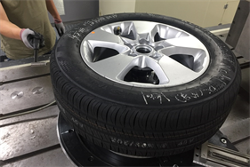 (a)
(a)  (b)
(b)
Figure 2. Tire-cavity-wheel impact test setup. (a) Test setup (fixed); (b) Impact hammer.
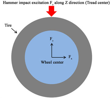
Figure 3. Tire-cavity-wheel diagram indicating the impact location and direction.
to several cords and rubber composites. These components play a role in maintaining the stiffness and strength required in a tire. The roles of tire components are well described in a book by Clark [18] . It consists of a radial carcass ply, two belt plies, bead wires, and several rubber components. The material composition of most tires is distinguished largely into the fiber-reinforced rubber (FRR) parts and the remaining pure rubber part. The FRR parts of the tire model considered here are composed of a single-ply polyester carcass, two steel belt layers, and several steel bead cords. Since the FRR parts are in the highly complex structure, their material models are chosen based on the goal of the numerical simulation.
Figure 4 shows the 2D finite element mesh on the general structure of tire-cavity-wheel model. The finite element model of a tire is shown in a sectional view and is representative of a passenger car tire. The wheel is modeled as an elastic solid. In order to simplify the assembly of all components, we define the same condensed nodes on the tire than those on the rim. With an axisymmetrical meshing of the tire, a meridian plan is created every 4 degrees. A 3D finite element model of tire-cavity-wheel assembly is shown in Figure 5. A simple Mooney-Rivlin law is used to model the strain energy potential of the rubber materials.
The viscoelastic nature of rubber uses the prony series in simulation. A small amount of material damping is applied to the rubber in the form of Rayleigh damping. The plies and belts are modeled using rebar layers that are embedded in the surrounding rubber matrixby Abaqus [14] . The hypo-elastic material properties are applied to the reinforcement fibers. The vibration characteristics are determined in an analysis sequence consisting of 5 steps as shown in Figure 6.
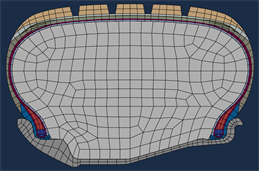
Figure 4. Example of 2-D tire-cavity-wheel meshing.

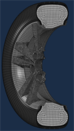
Figure 5. Finite element model of 3D tire-wheel-cavity assembly model.
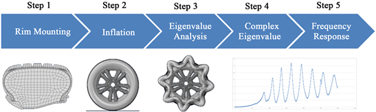
Figure 6. Flow chart for finite element analysis of the force transmissibility.
• Step 1: Rim Mounting Analysis
Rim mounting is carried out using a 2D axisymmetric model of the tire cross-section, which saves significant analysis time. Leveraging the symmetry of the model and the loading conditions, only one half of the tire is modeled. Axisymmetric elements with twist are used to capture the out-of-plane deformation introduced by the belts.
• Step 2: Inflation Analysis
The symmetric model generation capability is used to revolve the 2D axisymmetric cross-section into a partial three-dimensional model. Inflation is carried out using a 3D model which made symmetric model generation of Abaqus [14] . The spoke of wheel is imported by 3D FE model using the tetra elements. Uniform mesh density around the circumference is used in this study.
• Step 3: Frequency Extraction
An eigenvalue analysis is performed after both the staticinflation steps to compute the natural frequencies and mode shapes of the tire in its stationary.
• Step 4: Complex Eigenvalue Extraction
The modes of the tire, computed in the referenceframe associated with the Eulerian-Lagrangian scheme, are complex due to the contributions from the gyroscopicterms. The complex frequency extraction procedure uses a subspace projection method based on the eigenmodes extracted in the frequency extraction step (Step 3).
• Step 5: Steady State Dynamics
A subspace-based steady state dynamics procedure is used to compute the frequency response of the tire to an applied excitation. The subspace projection method uses the eigenmodes extracted in the frequency extraction step (Step 3). The forced response analysis is performed for stationary conditions.
3.2. Validation of Finite Element Analysis
In order to validate FEA-based force transmissibility model, the four tires tested at the indoor room are checked with the model. Figure 7 shows the frequency response of tire-cavity-wheel assembly of 175/65R15 size. A simulation result is shown to be in good agreement with the results from the indoor test. The first peak of frequency response is 84 Hz and the peak corresponding to the tire cavity resonance mode at 250 Hz is located. As shown in Table 1, the 1st peak frequency and the cavity peak frequency is applied to compare the test and the

Figure 7. Tire-cavity-wheel FRF of the test and simulation.

Table 1. The comparison between FEA and indoor test.
simulation. The results of tests and simulations on four tires are compared as having a very high correlation. It is shown that the analysis model in this paper can be effectively used to identify the tire modes that play a role, and recommend design changes that can solve the problem such as the improved structure borne noise design of tire.
4. Parametric Study
An important feature of the finite element model is that it provides a cost-effective means of carrying out parametric studies on the tire so as to optimize desired performance output. As a result of this, the properties of force transmissibility of tire-wheel assembly can be optimized to achieve a low 1st peak frequency. Based on the finite element analysis results well-fitting with the test results, we will try to implement DOE-based on tire design factors. The tire design parameters for DOE of the force transmissibility are performed by using the density of rubber, the modulus of rubber, and the cord stiffness.
4.1. The Effect of Rubber Density
In order to analyze the effect of rubber density, the level of DOE is selected form 95% to 100% of rubber density of tire components as listed in Table 2. The version for the finite element analysis of tire-cavity-wheel assembly is preceded by full factorial, 16 versions in total, and analyzed by using Minitab software [16] .
Table 2. Design table to analyze the effect of rubber density.
We used the 175/65R15 and 225/55R18 tire models. In this finite element analysis, there was no effectiveness factors, but through Minitab software analysis, we found that tread rubber and under-tread rubber have some influence. As the density of rubber increases, the 1st peak frequency of the force transmissibility tends to decrease as shown in Figure 8. It is found that the design parameter on the effect of rubber design on the force transmissibility of tire-cavity-wheel assembly is the density of tire tread rubber as shown in Pareto chart.
4.2. The Effect of Rubber Modulus
Table 3 shows the level for DOE for the effect of rubber modulus, and the level is from 80% to 120%. The versions for finite element analysis are preceded by full factorial. In Figure 9, there are two effectiveness factors; the modulus of tread and under-tread rubber. Especially, as the modulus of body ply topping rubber increases, the 1st frequency increased significantly. The body ply topping rubber is the rubber coating that encapsulates the radial ply reinforcing cords. The topping rubber is calendered onto the body ply cords in thin sheets. It is analyzed that the reason is that the body ply provide the strength to contain the air pressure and provide for sidewall impact resistance.
4.3. The Effect of Cord Stiffness
The tire cords used in the tire consist of belt, body ply, capply. The cord is able to express stiffness with Ends PerInch (EPI) concept, so we used in the DOE as Table 4. EPI is the number of warp threads per inch of woven fabric. In general, the higher the ends per inch, the finer the fabric. Figure 10 shows the effect of the cord stiffness such as EPI on the 1st frequency of force transmissibility of tire-cavity-wheel assembly. There is no effectiveness factor as shown in Pareto chart. It is concluded that the effect of capply and body ply on the 1st peak frequency of the force transmissibility are noticeable, and the effect of the belt is minimal.
5. Conclusion
A numerical method for predicting the force transmissibility of tire-cavity-wheel assembly under a free-fixed condition has been introduced in this paper to reduce the time and cost that is required for indoor test of a tire at the tire design. The results of finite element analysis for force transmissibility are shown to be in good agreement with the results from the indoor test. In order to improve structure borne noise, it is required to lower the 1st peak frequency of force
Table 3. Design table to analyze the effect of rubber modulus.

Figure 8. Graphical interpretation to the DOE for the effect of rubber density. (a) 175/65R15; (b) 225/55R18.

Figure 9. Graphical interpretation to the DOE for the effect of rubber modulus. (a) 175/65R15; (b) 225/55R18.

Figure 10. Graphical interpretation to the DOE for the effect of cord stiffness. (a) 175/65R15; (b) 225/55R18.
Table 4. Design table to analyze the effect of rubber density.
transmissibility. The effect of the tire design parameters such as the density and modulus of a rubber and the cord stiffness on the 1st peak frequency of force transmissibility is discussed. It is found that to increase the rubber density and to decrease the rubber modulus and the cord stiffness reduce the 1st peak frequency of the force transmissibility of the tire-cavity-wheel assembly. It is found that the prediction of the force transmissibility model using finite element analysis will be useful for the improvement of the structure borne noise performance of tire. In the future, it is expected that this finite element modeling technique for predicting the force transmissibility is a step forward for the automotive industry to evaluate tire-cavity-wheel assembly characteristics and the vehicle transfer functions.
Acknowledgements
The present study was supported by the Center for Environmentally Friendly Vehicles (CEFV) under the project “Development of the global top eco-friendly tire for reduction of tire wear particles and carbon dioxide” through the Ministry of Environment (ME, Republic of Korea).
Conflicts of Interest
The authors declare no conflicts of interest regarding the publication of this paper.
Cite this paper
Park, W.C., Lim, H.K., Jeong, K.M. and Kim, T.W. (2018) The Effect of Tire Design Parameters on the Force Transmissibility. Open Journal of Applied Sciences, 8, 446-458. https://doi.org/10.4236/ojapps.2018.810035
References
- 1. Law, S.S., Li, J. and Ding, Y. (2011) Structural Response Reconstruction with Transmissibility Concept in Frequency Domain. Mechanical Systems and Signal Processing, 25, 952-968. https://doi.org/10.1016/j.ymssp.2010.10.001
- 2. Maia, N.M.M., Urgueira, A.P.V. and Almeida, R.A.B. (2012) An Overview of the Transmissibility Concept and Its Application to Structural Damage Detection, Topics in Modal Analysis I. Proceedings of the Society for Experimental Mechanics Conference, Vol. 5, 30 January-2 February 2017, Garden Grove, 137-151.
- 3. Sampaio, R.P.C., Maia, N.M.M., Ribeiro, A.M.R. and Silva, J.M.M. (1999) Damage Detection Using the Transmissibility Concept. Proceedings of the 6th International Congress on Sound and Vibration (ICSV 6), Copenhagen, 5-8 July 1999, 2559-2568.
- 4. Devriendt, C., De Sitter, G. and Guillaume, P. (2010) An Operational Modal Analysis Approach Based on Parametrically Identified Multivariable Transmissibilities. Mechanical Systems and Signal Processing, 24, 1250-1259. https://doi.org/10.1016/j.ymssp.2009.02.015
- 5. Urgueira, A.P.V., Almeida, R.A.B. and Maia, N.M.M. (2008) Experimental Estimation of FRF’s Using the Transmissibility Concept. Proceedings of the International Conference on Modal Analysis Noise and Vibration Engineering (ISMA 2008), Leuven, 15-17 September 2008, 1807-1814.
- 6. Urgueira, A.P.V., Almeida, R.A.B. and Maia, N.M.M. (2011) On the Use of the Transmissibility Concept for the Evaluation of Frequency Response Functions. Mechanical Systems and Signal Processing, 25, 940-951. https://doi.org/10.1016/j.ymssp.2010.07.015
- 7. Nevew, M.M. (2010) Estimation of Transmitted Forces Using the Transmissibility Concept for Multiple Degrees of Freedom. Proceedings of the International Conference on Modal Analysis Noise and Vibration Engineering (ISMA 2010), Leuven, 20-22 September 2010, 3887-3897.
- 8. Lage, Y.E., Maia, N.M.M., Neves, M.M. and Ribeiro, A.M.R. (2013) Force Identification Using the Concept of Displacement Transmissibility. Journal of Sound and Vibration, 332, 1674-1686. https://doi.org/10.1016/j.jsv.2012.10.034
- 9. Tchemiak, D. (2009) Application of Transmissibility Matrix Method to Structure Borne Path Analysis. Proceedings of NAG/DAGA Conference, 23-26 March 2009, Rotterdam, 1691-1694.
- 10. Tchemiak, D. and Schumacher, A.P. (2009) Application of Transmissibility Matrix Method to NVH Source Contribution Analysis. Proceedings of the 27th International Modal Analysis Conference (IMAC XXVII), Orlando, 9-12 February 2009, Orlando, 2076-2085.
- 11. Tchemiak, D. (2010) Application of Operational Noise Path Analysis to Systems with Rotational Degrees of Freedom. Proceedings of the International Conference on Noise and Vibration Engineering (ISMA 2010), Leuven, 20-22 September 2010, 3943-3952.
- 12. Lage, Y.E., Neves, M.M., Maia, N.M.M. and Tcherniak, D. (2014) Force Transmissibility versus Displacement Transmissibility. Journal of Sound and Vibration, 333, 5708-5722. https://doi.org/10.1016/j.jsv.2014.05.038
- 13. GMW14876 (2014) Tire Force Transmissibility and Wheel Lateral Stiffness Evaluation Procedure. Worldwide Engineering Standards.
- 14. Dassault Systemes SIMULIA Corp. (2014) Abaqus Analysis User’s Manual Version 6.14. Providence.
- 15. Coppola, A. (1993) Design of Experiments. Total Quality Management Toolkit: An Encyclopedic Listing of TQM Tools. Defense Technical Information Center, 75-93.
- 16. Minitab (2015) Minitab Inc. http://www.minitab.com/zh-cn/
- 17. Nackenhorst, U. (2004) The ALE-Formulation of Bodies in Rolling Contact-Theoretical Foundations and Finite Element Approach. Computer Methods in Applied Mechanics and Engineering, 193, 4299-4322. https://doi.org/10.1016/j.cma.2004.01.033
- 18. Clark, S.K. (1982) Mechanics of Pneumatic Tires. US Department of Transportation, National Highway Traffic Safety Administration.