Modeling and Numerical Simulation of Material Science
Vol.3 No.4(2013), Article ID:37711,8 pages DOI:10.4236/mnsms.2013.34014
Modeling and Simulation of Laser Assisted Turning of Hard Steels
1Military Technical College, Cairo, Egypt
2Libyan National Army, Tripoli, Libya
3Military Technical College, Cairo, Egypt
4Central Metallurgical R & D Institute, Cairo, Egypt
Email: Omar_787mtc@yahoo.com, m_sobeih2001@yahoo.com, amro.youssef@gmail.com, *elbatahgy@yahoo.com
Copyright © 2013 Omar Abdulghani et al. This is an open access article distributed under the Creative Commons Attribution License, which permits unrestricted use, distribution, and reproduction in any medium, provided the original work is properly cited.
Received March 18, 2013; revised August 16, 2013; accepted September 1, 2013
Keywords: Laser assisted turning; Hard steels; Three-dimensional modeling; User-defined function; Temperature distribution
ABSTRACT
This research work is focused on simulation of laser assisted turning as a new solution for machining of hard steels. A transient, three-dimensional model was developed to predict the temperature distribution of a rotated cylindrical steel workpiece subjected to a localized heating using a moving Gaussian laser beam. In this regard, a User-Defined Function was created to overcome the problem of a moving Gaussian heat source’ definition. This User-Defined Function was compiled into a finite volume software package (Fluent®), where three-dimensional single precision solver was used for analysis. Based on this model, simulation of the surface temperature of 32 mm diameter workpiece of AISI51 50H steel was performed as a function of time at a specific distance behind the laser beam spot, which is corresponding to 30˚ angle from the laser beam. The simulation results were compared with other published data of the same steel type where a close agreement was obtained. The verified model was used for simulation of laser assisted turning of 20 mm diameter workpiece of AISI D2 tool steel. The cutting depth, behind the laser beam, was set at a distance corresponding to 60˚ angle from the laser beam for having sufficient access for handling both laser head and cutting tool. This cutting depth was studied as a function of different lasers and machining parameters. The results indicated that the optimum parameters for successful laser-assisted turning process of the concerned steels are 800 W laser power, 5 mm laser beam spot diameter, 20 sec preheating time, 0.8 mm/sec laser scanning speed, 300 rpm rotational speed and 0.8 mm/sec feed rate. These parameters ensure easy/successful cutting of 1 mm depth in one pass without deteriorating the properties of the remaining bulk material. It can be deduced that the developed model might provide a useful tool for online process control of different steel types regardless of their physical properties and geometries.
1. Introduction
Hard steel alloys are widely used in various important applications such as automotive industry, die and mold industries as well as cutting purposes including shear blades, punches and piercers. Manufacturers of hard components constantly strive for lower cost solutions as well as higher quality in order to maintain their competitiveness. Conventional hard machining processes that may be used in pre-grinding or pre-finishing operations result in low quality. Besides, it is still an expensive and complicated solution that in turn restricts the applications of high-performance hard steels [1-5].
The new solution is the hot machining, which combines a heating source with conventional machining methods. Hot machining has emerged as a promising technique for hard materials that are difficult to cut. Besides, the workpiece is softened by heating during machining. It is showing a great promise in increasing the productivity and improving the quality due to a remarkable reduction in both cutting forces and tool wear [6-8].
Among hot machining processes is the laser assisted machining that combines laser beam technology with traditional machining methods such as turning and milling. Laser assisted machining is characterized by removal of controlled localized heated metal, which means maintaining the properties of the remaining bulk material. It is considered as a new and innovative way of machining the materials that are difficult to cut in the hardened state, such as ceramics, nickel based super alloys, titanium alloys and hardened ferrous alloys. Effectiveness of the laser assisted machining has already been demonstrated by different researchers [9-15]. Although scientific work on this area has contributed to understanding the process, there are still unresolved problems. Deep understanding of this process fundamentals including temperature distribution at material removal zone as a function of laser and machining parameters as well as material physical properties is of considerable importance regarding the machining quality.
It is extremely difficult or impossible to directly measure the parameters of interest such as heat depth or temperature distribution inside the workpiece during machining. In comparison with experimental work, modeling and simulation are of remarkable importance regarding accuracy and economy aspects. Numerical modeling has been proven to be an efficient method to understand physical phenomena and to predict control parameters of a certain process [16-18]. Mathematical models do not only allow an estimation of such parameters but also have the ability to lead into new directions due to the detailed analysis that can be achieved.
Mathematical modeling and simulation have been developed and used to understand and gain insight into the various mechanisms which take place during heating of a rotating workpiece using a moving laser beam. Transient three-dimensional model of a rotating workpiece undergoing laser heating and material removal was developed and used for different materials including mainly ceramics as well as titanium alloys [19-23]. However, research work for a moving Gaussian laser heat source to predict depth of heat-affected zone and temperature distribution in a Cartesian coordinates of hard steels is far from complete and more research work is required.
The current study aims at modeling and simulation of the laser assisted turning of hard steels for deep understanding of the temperature distribution at the material removal zone as a function of both laser and machining parameters.
2. Mathematical Modeling and Simulation
2.1. Mathematical Modeling
The concept of laser-assisted machining of hard steels is based on using a laser as a heat source with the beam positioned directly in front of the cutting tool to heat and soften the work metal selectively before machining. In this case, the laser beam energy is absorbed by the workpiece surface and converted to thermal energy to produce rapid heating and softening of the part’s upper layer reducing the cutting forces and thereby increasing the ease of material removal.
Schematic illustration of a rotated cylindrical workpiece subjected to laser heating is shown in Figure 1. To simulate the temperature distribution in this case, transient 3-dimensional numerical model was developed based on Rozzi et al model [21,22].
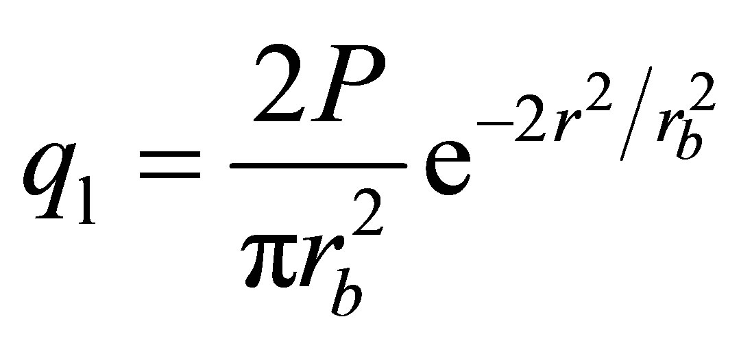
The laser heat source is assumed to have Gaussian distribution with a maximum heat flux at the laser beam spot center. The laser heat flux is a function of the laser power, the laser beam spot radius and the radial distance from the laser beam spot center, as shown in equation (1) [24].
 , (1)
, (1)
where ql is the laser heat flux, P is the laser power, rb is the radius of laser beam spot at the workpiece surface, and r is the radial distance from the laser beam spot center.
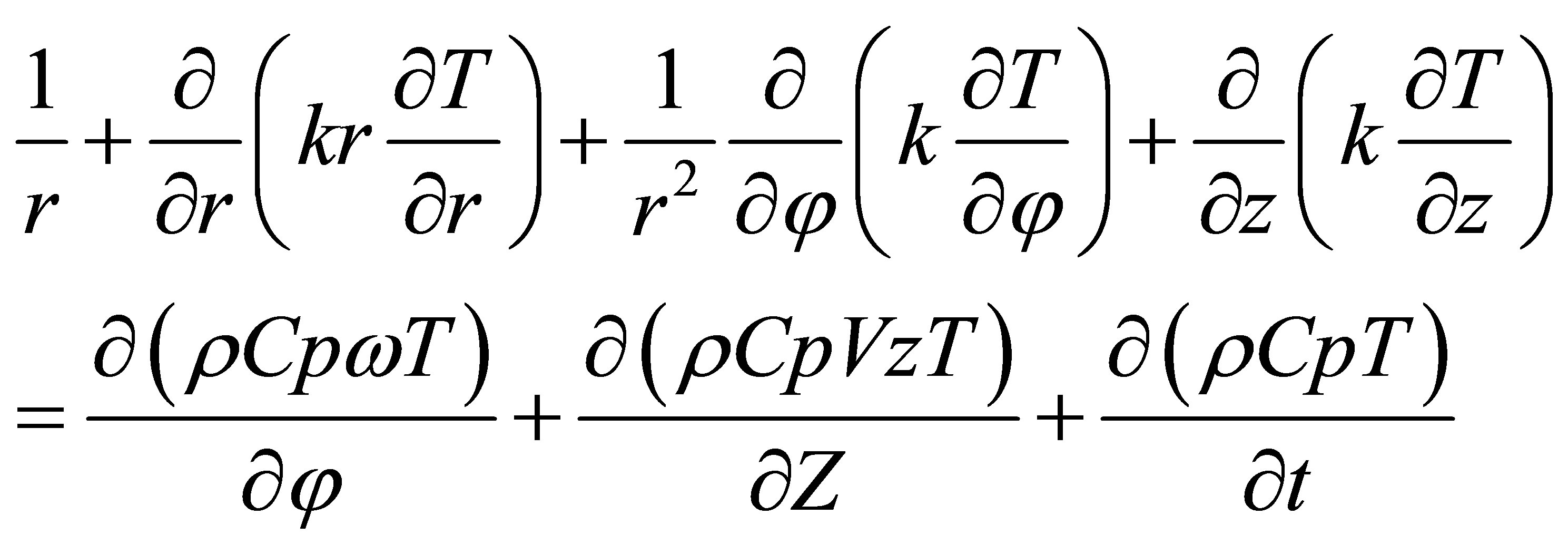
Assuming isotropic thermal conductivity and neglecting the convection effect of the laser gas jet, the heat is generated due to oxidation resulted from high temperature of the laser beam heating. The governing heat conduction equation in case of a rotated workpiece undergoing moving heat source is as following [21,22].
 (2)
(2)
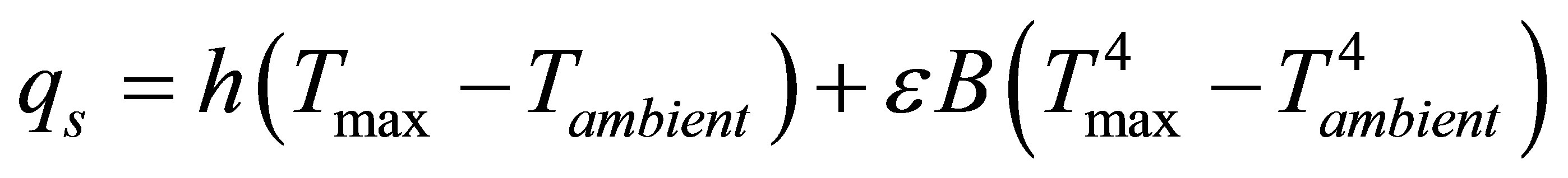
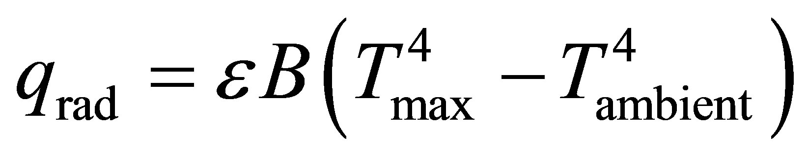
To calculate the heat flux losses to ambient or surroundings, both convection and radiation boundary conditions are applied to the workpiece surface and the following equation was used.
 (3)
(3)
The initial condition is T
 (4)
(4)
and the boundary conditions are as following:
• At the laser beam spot:
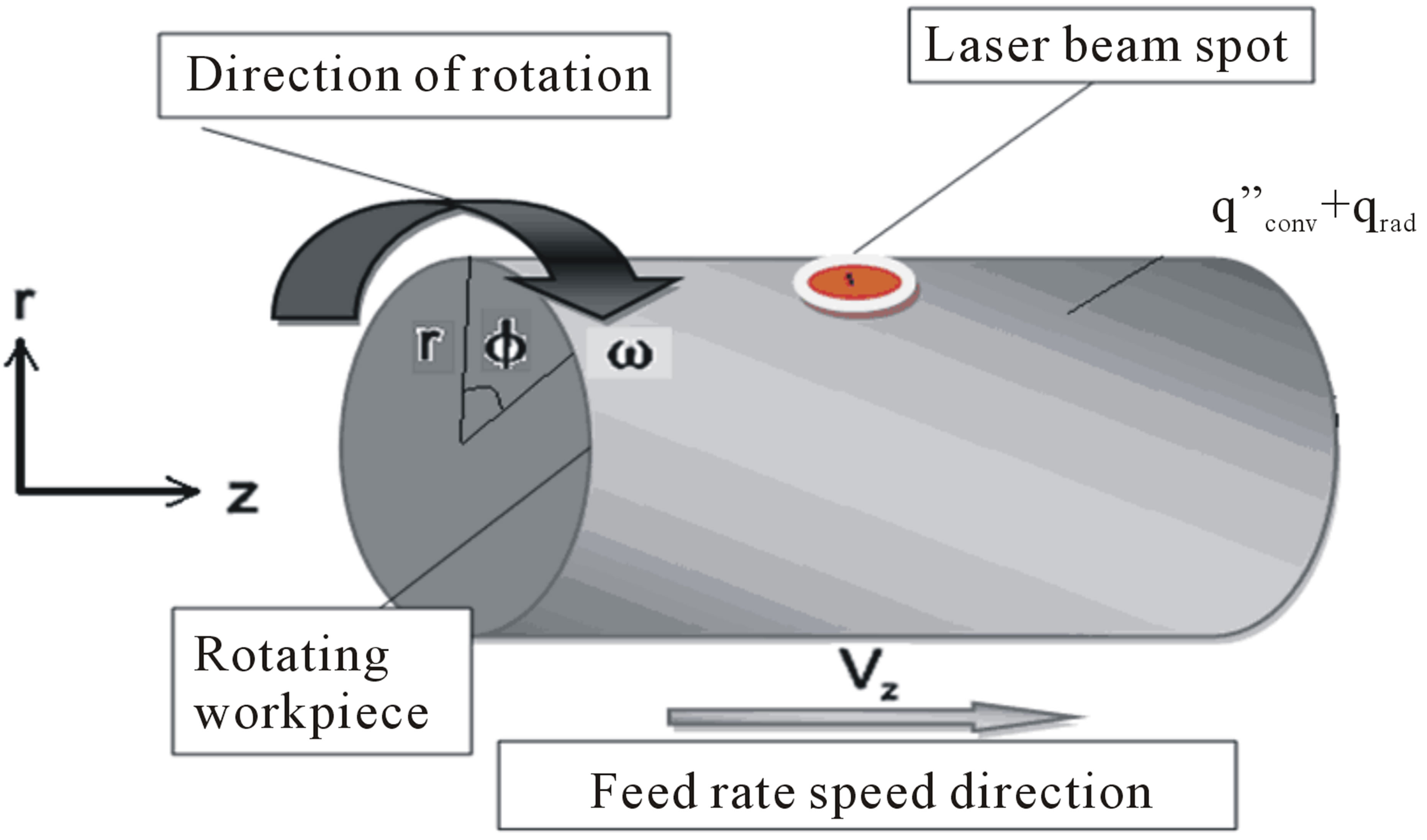
Figure 1. Schematic illustration of a rotated cylindrical workpiece subjected to laser heating.
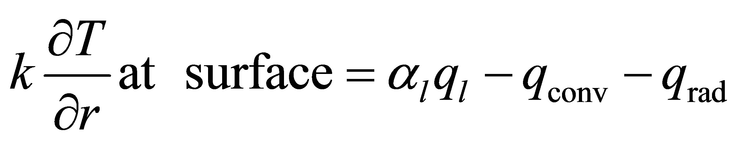 (5)
(5)
• Off the laser beam spot:
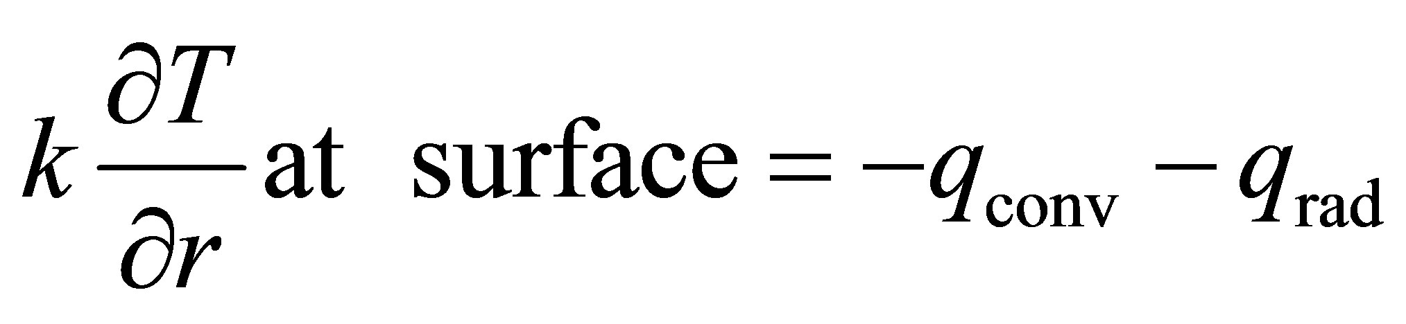 (6)
(6)
where
 (7)
(7)
 (8)
(8)
 is the maximum surface temperature out of the laser beam spot.
 is the ambient temperature.
2.2. Simulation of the Model
For simulation of the above model, AISI51 50H hot worked tool steel was selected based on an available experimental data for this type of steel [20]. In this regard, a rotated workpiece with 32 mm diameter and 100 mm length subjected only to translating laser heating with no material removal was considered.
Chuck holder of the workpiece has not been included in the model. As only the heat transfer process is analyzed, the workpiece divided into four regions including surface, interior and two sides. The summation of the cells is 288,234 cells including 878,799 faces and 302,596 nodes. Figure 2 shows meshes created by Gambit-CFD for the used workpiece. Once the modeling and meshing have been done, the grid is imported into a finite volume software package (Fluent®), where three-dimensional single precision solver was used for analysis. The next step of the model development is the definition of the material properties as well as the definition of a moving Gaussian heat source. The thermo physical properties of AISI51 50H steel are given in Table 1. Since transient boundary conditions cannot be defined by the fluent user-interface, a User-Defined Function was created, using C language, (Figure 3) to enable applying a heat flux to a rotating cylindrical workpiece. This User-Defined Function is very important to customize the Fluent Code to calculate the heat flux as a particular modeling need. The heat flux is defined as a custom boundary profile that varies as a function of spatial co-ordinates and time. The established User-Defined Function is compiled at the run time by built-in complier/interpreter in the Fluent Code. Once the User-Defined Function is interpreted, the function is available in the graphical interface of the Fluent Code. This User-Defined Function is called at every time step, where the laser heat flux center is calculated as a function of time. The User-Defined Function loops cover all the cell faces on the surfaces, where the distance between the center of each cell face and the laser spot is calculated. If this distance is equal to or less than the laser spot radius then, the heat flux is calculated
Figure 2. Meshes created by Gambit-CFD for the used workpiece.
Table 1. Thermo physical properties of AISI51 50H steel [20].
Figure 3. Flow chart of User-Defined Function created to enable applying a heat flux to a rotating cylindrical workpiece. P is the power input, rb is the laser beam radius, Vz is the linear speed of laser beam, t is the interaction time, r is the distance from the laser beam spot center, d is the offset distance.
using equation (5). Otherwise Equation (6) is used in case of convection and radiation condition.
2.3. Model Validation
Based on the above simulation, surface temperature of the used steel workpiece was calculated as a function of time at a specific distance behind the laser beam spot, which is corresponding to 30˚ angle from the laser beam. To ensure maximum uniform heat distribution without damaging/melting of the workpiece, the laser beam spot was defocused and kept constant at 5 mm diameter. Reflectivity of the material to the laser beam was considered as 50%.
The results were compared with other published data of the same used steel, which included both experimentally measured and calculated values based on a transient, three-dimensional model [20]. This comparison disclosed a close agreement between both present and published results, as shown in Figure 4.
3. Results and Discussion
The verified model was used for simulation of laser-assisted turning process of a different tool steel (AISI D2) having different dimensions. In this regard, a workpiece with 20 mm diameter and 300 mm length was considered. The thermo physical properties of this steel type are given in Table 2. The cutting depth was studied as a function of different laser-assisted turning parameters including preheating time, laser power, laser scanning speed and workpiece rotational speed. Then, the proper laser-assisted turning parameters were determined. In order to avoid damage of the laser head and for having sufficient access for handling both laser head and cutting tool, the cutting zone behind the laser head was set at 60˚ angle from the laser beam, as shown schematically in Figure 5.
It is speculated that the hardness of AISI D2 tool steel is decreased and subsequently its toughness is improved with heating above 540˚C due to softening. The maximum cutting depth is decided based on this temperature for easy and successful cutting process. In other words, the maximum cutting depth is considered as the depth heated above 540˚C. The temperature of the remaining bulk material is kept below 540˚C to minimize its microstructure change and then to maintain its properties.
3.1. Effect of Preheating Time
For easy and successful cutting, it is of considerable importance to maintain uniform temperature distribution during the laser-assisted turning process. In this concern, the preheating time before starting metal removal has a remarkable effect. It is necessary to match the preheating time with the other parameters of the laser-assisted turning process so that steady-state temperature distribution is achieved, just at the beginning of metal removal. To ensure maximum uniform heat distribution, without damaging/melting the workpiece or tool, the laser beam spot was defocused and kept constant at 5 mm diameter. Reflectivity of the used steel to the laser beam was consi-
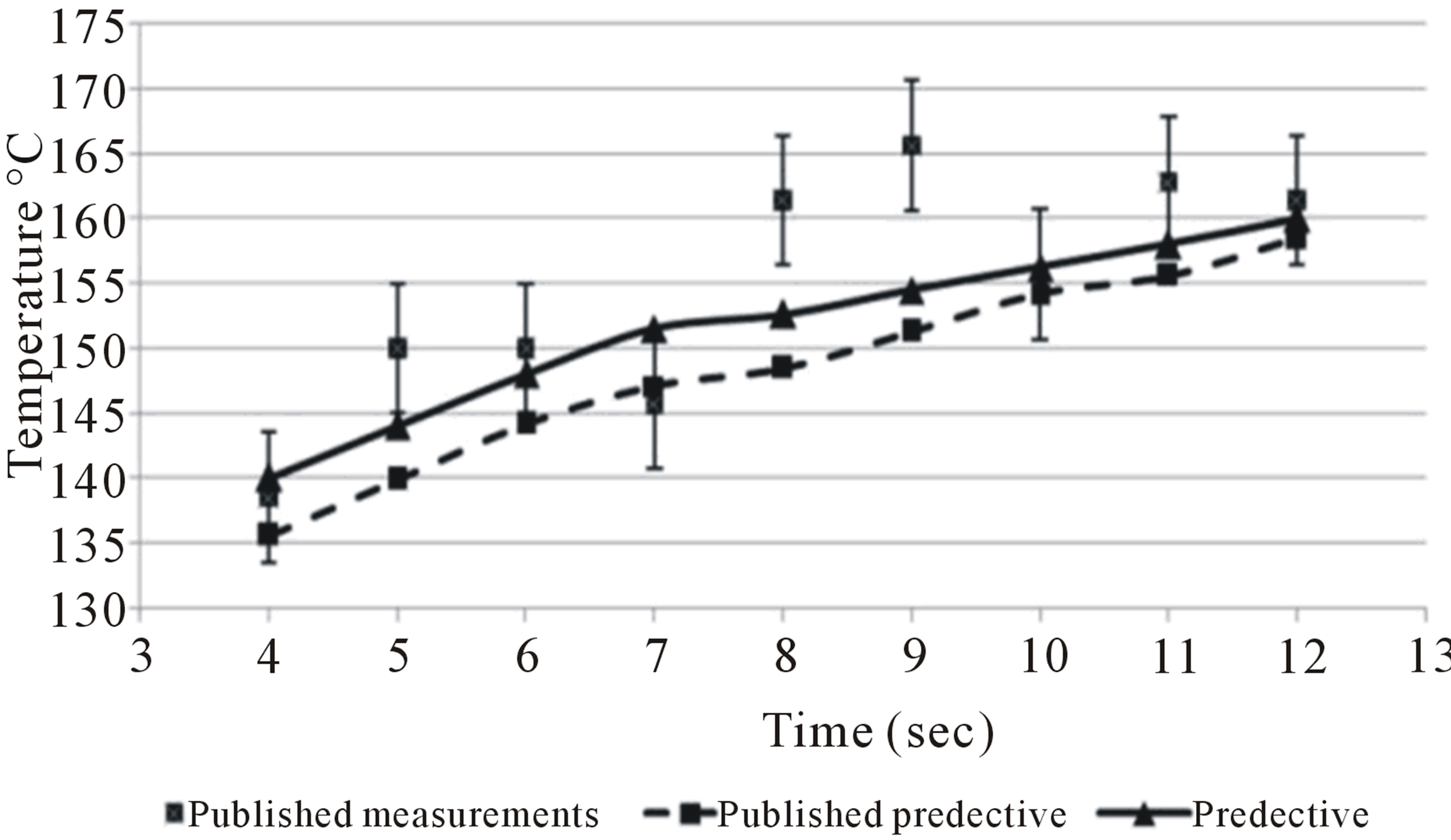
Figure 4. Comparison between the present results of calculated surface temperature as a function of time and other experimentally measured and calculated data [20]. Laser power: 500W; Laser scanning speed: 0.4 mm/s; Rotational speed: 6 rpm.
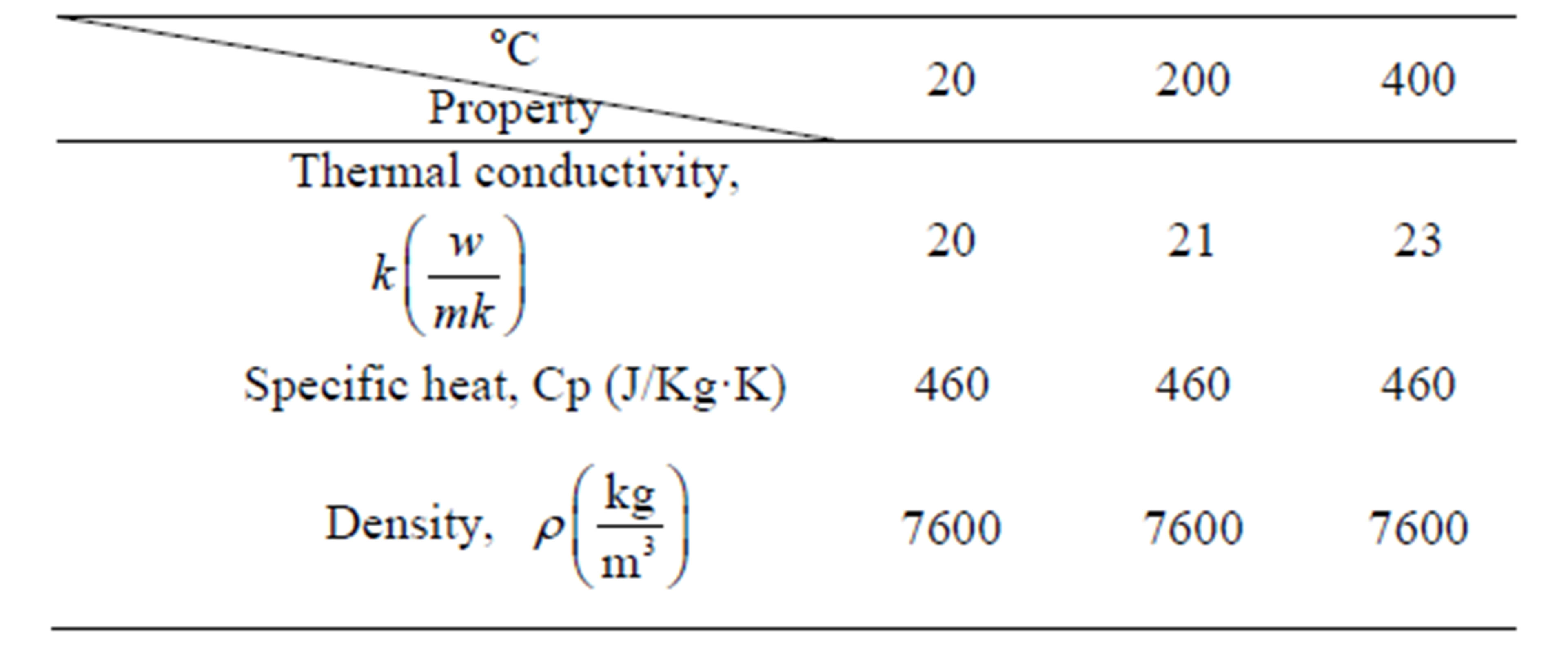
Table 2. Thermo physical property of AISI D2 steel [25].
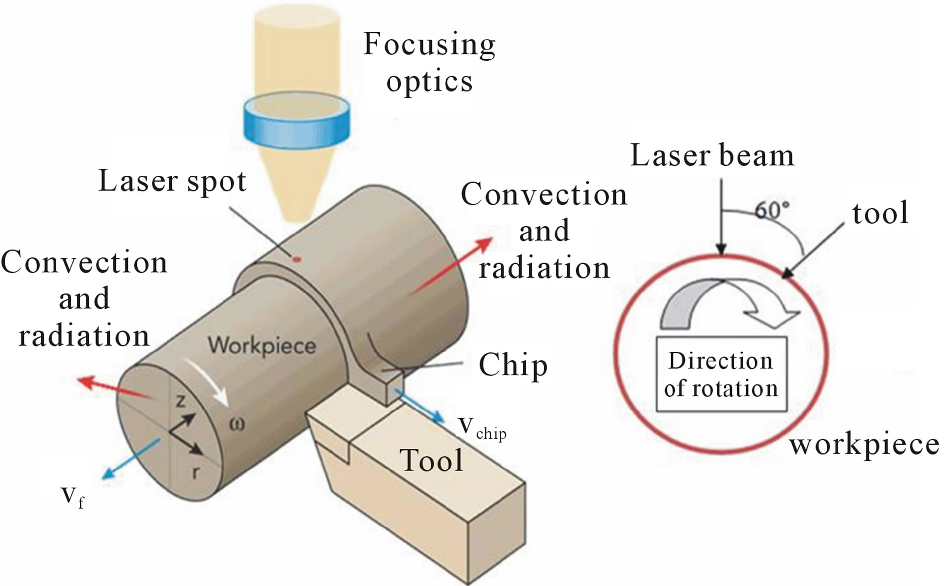
Figure 5. Schematic illustration of a laser-assisted turning process.
dered as 50%.
For clarifying the effect of preheating time, the surface temperature was calculated at different preheating times (10, 20, 30 sec) while other parameters were kept constant at 800 W laser power, 0.0 mm/sec laser scanning speed, 300 rpm rotating speed and 0.0 mm/sec feed rate. The laser power was selected based on an available CO2 laser system having a maximum output power of 1000W. The rotational speed was selected based on previous accumulated practical machining experience. Figure 6 shows an example of three-dimensional surface temperature distribution after 20sec preheating of 20 mm
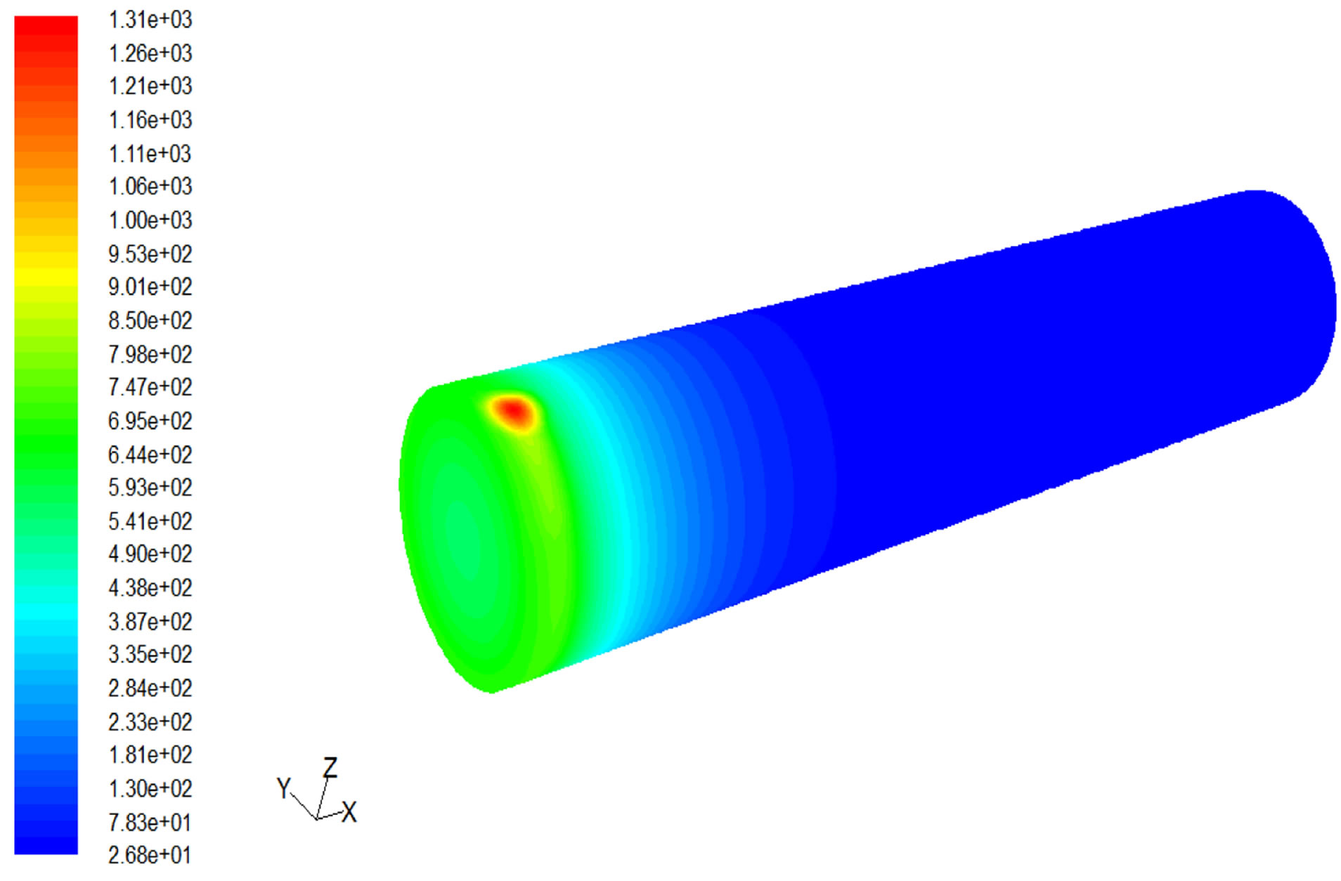
Figure 6. Three dimensional surface temperature distribution after 20 sec preheating of 20 mm diameter workpiece with other parameters kept constant at 800 W laser power, 0.0 mm/sec laser scanning speed, 300 rpm rotating speed and 0.0 mm/sec feed rate.
diameter workpiece with other parameters kept constant. It is found that 20 sec is the optimum preheating time for successful cutting since longer preheating time results in surface melting while shorter time results in insufficient heating for easy and successful cutting.
3.2. Effect of Laser Power
To clarify the effect of laser power on the cutting depth, three-dimensional heat distribution was calculated as a function of laser power with other parameters kept constant at 20 sec preheating time, 0.8 mm/sec laser scanning speed, 300 rpm rotational speed and 0.8 mm/sec feed rate. It should be reported that 0.8 mm/sec feed rate was selected based on previous accumulated practical machining experience. Based on the selected feed rate, the laser scanning speed was set at the same value; 0.8 mm/sec.
Figure 7 shows the temperature distribution through the depth as a function of the laser power with the other parameters kept constant. It can be noticed that laser power lower than 800 W has resulted in insufficient surface heating (450˚C maximum). This means insufficient reduction in the hardness of the outer layer and then, difficult or unsuccessful cutting. Increasing the laser power to 800 W has resulted in increasing the surface temperature to 595.6˚C, which is sufficient for easy/successful cutting. Based on the minimum temperature (540˚C) required to reduce hardness for easy cutting, the maximum depth that can be successfully cut in this case is 1mm where proper temperature (546˚C) is still existed. More increase in laser power (1000 W) has resulted in 735.63˚C surface temperature and 540˚C at 5 mm depth, which is still within the cutting range. In other words, increasing the laser power to 1000 W will increase the possible cutting depth to 5 mm. However, this cutting condition is not practically applicable since it is difficult to cut 5 mm depth in a one pass. For successful laser assisted turning process that means high cut quality with maintaining the properties of the remaining bulk material, the depth of the decreased hardness or softened layer should be completely removed in a one pass. It can be deduced that 800 W is considered as the optimum laser power regarding both quality and economy aspects.
3.3. Effect of Laser Scanning Speed
The effect of the laser scanning speed on the cutting depth was studied through calculation of three-dimensional heat distribution as a function of laser scanning speed with other parameters kept constant. In this concern, the laser scanning speed was varied between 0.2 and 1.0 mm/sec while the other parameters kept constant at 800 W laser power, 20sec preheating time, 300 rpm rotational speed and 0.8 mm/sec feed rate. Figure 8
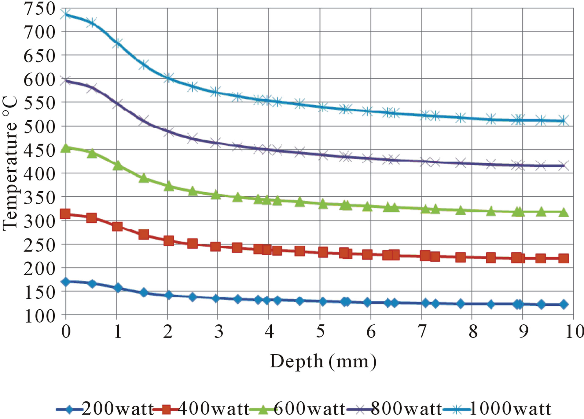
Figure 7. Temperature distribution through depth as a function of laser power with other parameters kept constant at 20 sec preheat time, 0.8 mm/sec laser scanning speed, 300 rpm rotational and 0.8 mm/sec feed rate.
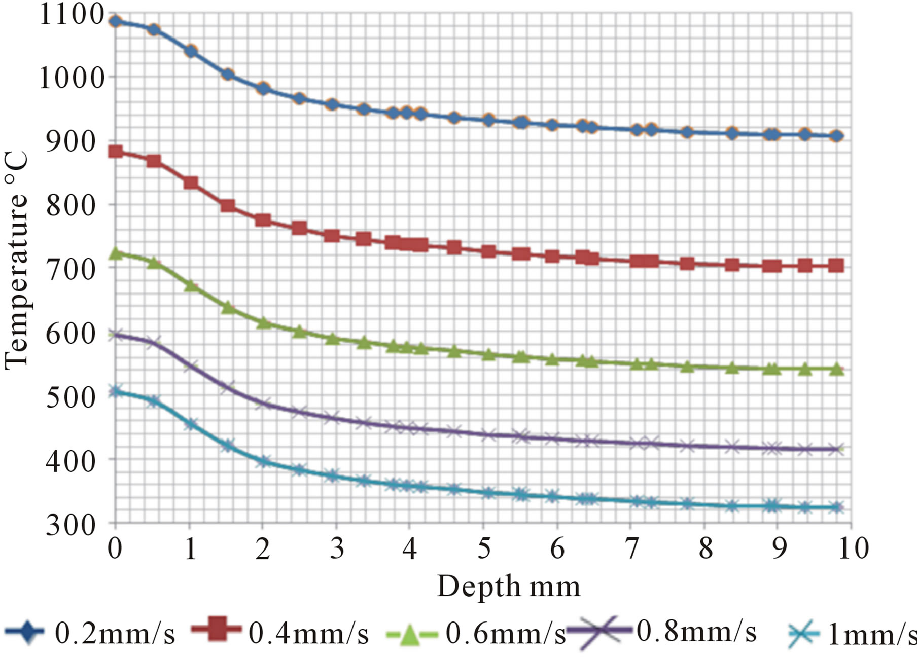
Figure 8. Temperature distribution through depth as a function of laser scanning speed with other parameters kept constant at 800 W laser power, 20 sec preheating time, 0.8 mm/sec feed rate and 300 rpm rotational speed.
shows the temperature distribution through the depth as a function of the laser scanning speed with the other parameters kept constant. For laser scanning speed range of 0.2 - 0.6 mm/sec, the surface temperature of the workpiece is increased up to 1088˚C due to massive or high heat input. The temperature is decreased up to 541˚C at 10 mm depth, which indicates that the workpiece center is located within the easy cutting range. However, this cutting condition is not applicable due to difficulty in removing such thick layer (10 mm depth) in a one pass. In addition, massive heat input will result in deterioration of the properties of both the remaining bulk material as well as the cutting tool.
Increasing the laser scanning speed to 0.8 mm/sec has resulted in acceptable heat distribution through the workpiece where surface temperature of 595.6˚C was obtained. Based on the required minimum heating temperature (540˚C) for easy cutting, the maximum depth that can be successfully cut is 1 mm. Increasing the laser scanning speed to 1 mm/s has resulted in a lower surface temperature (505˚C), which means insufficient heating for successful cutting. It can be deduced that 0.8 mm/sec is considered as the optimum laser scanning speed regarding both quality and economy aspects.
3.4. Effect of Workpiece Rotational Speed
Three-dimensional heat distribution was calculated for different rotational speeds with the other previously obtained optimum parameters kept constant. In this concern, the rotational speed was varied between 100 and 900 rpm while the other parameters kept constant at 800 W laser power, 20 sec preheating time, 0.8 mm/sec laser scanning speed and 0.8 mm/sec feed rate. Figure 9 shows the temperature distribution through depth as a function of the rotational speed with other parameters kept constant. For 100 rpm rotational speed and based on minimum heating temperature (540˚C) required for successful cutting, a depth of 1.5 mm should be completely cut or removed in a one pass in order to avoid deterioration of the properties of the remaining bulk material. Much better heat distribution through the depth was achieved with 300 rpm rotational speed, where 1 mm depth can be easily or successfully cut without deteriorating the properties of the remaining bulk material.
Increasing the rotational speed to 500 and 700 rpm has resulted in lower surface temperatures (570˚C - 554.57˚C), which are still sufficient for cutting. However, the maximum depth that can be easily or successfully cut is limited to 0.5 mm based on the required minimum heating temperature (540˚C). This relatively shallow cut depth is not economically reasonable. More increase in the rotational speed to 900 rpm has resulted in insufficient heating for easy/successful cutting of even 0.5 mm depth. This is due to insufficient heating temperature (534.7˚C) at this depth.
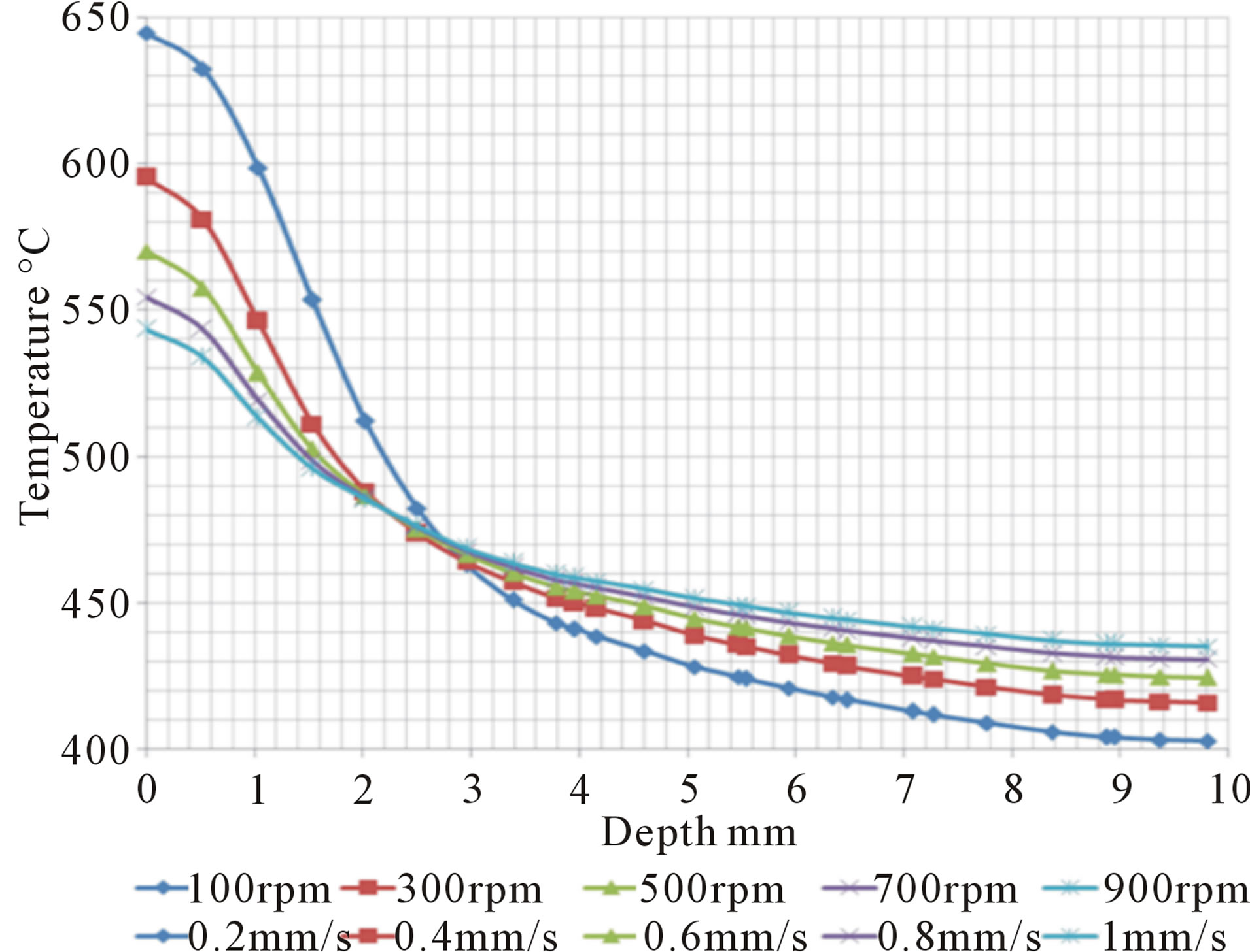
Figure 9. Temperature distribution through depth as a function of rotational speed with other parameters kept constant at 800 W laser power, 20 sec preheating time, 0.8 mm/sec laser scanning speed and 0.8 mm/sec feed rate.
Based on the above all results, the most suitable parameters for laser-assisted turning of the concerned steel are 800 W laser power, 5 mm laser beam spot diameter, 20 sec preheating time, 0.8 mm/sec laser scanning speed, 300 rpm rotational speed and 0.8 mm/sec feed rate. These parameters ensure successful cutting of 1 mm depth without deteriorating the properties of the remaining bulk material.
4. Conclusions
A transient, three-dimensional model was developed to predict the temperature distribution of a rotated cylindrical steel workpiece subjected to a localized heating using a moving Gaussian laser beam. In this concern, a UserDefined Function (C program) was established to overcome the problem of the definition of a moving Gaussian heat source. This User-Defined Function was compiled into a finite volume software package (Fluent®), where three-dimensional single precision solver was used for analysis. Based on this model, simulation of the surface temperature of 32 mm diameter workpiece of AISI51 50H steel was performed as a function of time at a specific distance behind the laser beam spot, which is corresponding to 30˚ angle from the laser beam. The simulation results were compared with other published data of the same steel type where a close agreement was obtained.
The verified model was used for simulation of laser assisted turning of 20 mm diameter workpiece of AISI D2 tool steel. The cutting zone behind the laser beam was set at a distance corresponding to 60˚ angle from the laser beam for having sufficient access for handling both laser head and cutting tool. Prediction of the cutting depth was done as a function of different lasers and machining parameters. The results indicated that the optimum parameters for successful laser-assisted turning process of the concerned steels are 800 W laser power, 5 mm laser beam spot diameter, 20 sec preheating time, 0.8 mm/sec laser scanning speed, 300 rpm rotational speed and 0.8 mm/sec feed rate. These parameters ensure easy /successful cutting of 1 mm depth in one pass without deteriorating the properties of the remaining bulk material.
It can be deduced that the developed model might provide a useful tool for online process control of different steel types regardless of their physical properties and geometry.
5. Acknowledgements
The authors would like to thank Prof. G. Baumann, Head of Mathematics Department at Germany University in Cairo for his valuable advice and fruitful discussion on mathematical modeling.
REFERENCES
- R. Poggie, “Wear of Materials,” Journal of Materials Science and Technology, Vol. 7, No. 2, 1991, pp. 387-406.
- A. Lima, “Hard Turning: AISI 4340 High Strength Low Alloy Steel and AISI D2 Cold Work Tool Steel,” Journal of Materials Processing Technology, Vol. 169, No. 3, 2005, pp. 388-395. http://dx.doi.org/10.1016/j.jmatprotec.2005.04.082
- S. Herbert, “Metal Cutting and High Speed Machining,” 2nd Edition, Springer, New York, 1994.
- G. Brain, “Manufacturing Surface Technology,” 3rd Edition, Taylor and Francis Inc., London, 2001.
- L. Bourithisa, “Comparison of Wear Properties of Tool Steels AISI D2 and O1 with the Same Hardness,” Tribology International, Vol. 39, No. 6, 2006, pp. 479-489. http://dx.doi.org/10.1016/j.triboint.2005.03.005
- L. Zler, “Theoretical and Experimental Determination of Tool Life in Hot Machining of Austenitic Manganese Steel,” International Journal of Machine Tools and Manufacture, Vol. 41, No. 2, 2001, pp. 163-172. http://dx.doi.org/10.1016/S0890-6955(00)00077-8
- J. A. Sanchez, “Plasma Assisted Milling Heat-Resistant Superalloys,” Journal of Manufacturing Science and Engineering, Vol. 126, No. 2, 2004, pp. 274-285. http://dx.doi.org/10.1115/1.1644548
- S. Sun, M. Brandt and M. Dargusch, “Thermally Enhanced Machining of Hard-to-Machine Materials,” International Journal of Machine Tools and Manufacture, Vol. 50, No. 8, 2010, pp. 663-680. http://dx.doi.org/10.1016/j.ijmachtools.2010.04.008
- M. Anderson, R. P. Yung and C. Shin, “Laser-Assisted Machining of Inconel 718 with an Economic Analysis,” International Journal of Machine Tools and Manufacture, Vol. 46, No. 14, 2006, pp. 1879-1891. http://dx.doi.org/10.1016/j.ijmachtools.2005.11.005
- S. Rajagopal, “Machining Aerospace Alloys with the Aid of a 15kW Laser,” Journal of Applied Metal Work, Vol. 2, No. 3, 1982, pp. 170-184. http://dx.doi.org/10.1007/BF02834035
- S. Sun, “Parametric Investigation of Laser-Assisted Machining of Commercially Pure Titanium,” Advanced Engineering Materials, Vol. 10, No. 6, 2008, pp. 565-572. http://dx.doi.org/10.1002/adem.200700349
- B. Yang, “Laser-Assisted Milling of Silicon Nitride Ceramic :A Machinability Study,” International Journal of Mechatronics and Manufacturing Systems, Vol. 1, No. 1, 2008, pp. 116-130. http://dx.doi.org/10.1504/IJMMS.2008.018282
- F. E. Pfefferkorn, et al., “Laser Assisted Machining of Magnesia-Partially Stabilized Zirconia,” Journal of Manufacturing Science and Engineering, Vol. 126, No. 1, 2005, pp. 346-357.
- P. Dumitrescu, et al., “High-Power Diode Laser Assisted Hard Turning of AISI D2 Tool Steel,” International Journal of Machine Tools and Manufacture, Vol. 46, 2006, pp. 2009-2016. http://dx.doi.org/10.1016/j.ijmachtools.2006.01.005
- A. N. Samant and N. B. Dahotre, “Laser Machining of Structural Ceramics—A Review,” Journal of European Ceramic Society, Vol. 29, No. 6, 2009, pp. 969-993. http://dx.doi.org/10.1016/j.jeurceramsoc.2008.11.010
- J. Mazumder and W. M. Steen, “Heat Transfer Model for CW Laser Materials Processing,” Journal of Applied Physics, Vol. 51, No. 2, 1980, pp. 941-947. http://dx.doi.org/10.1063/1.327672
- K. S. Yeung and P. H. Thornton, “Transient Thermal Analysis of Spot Welding Electrodes,” Welding Journal, Vol. 78, No. 1, 1999, pp. 1S-8S.
- D. Mandelprot, “Modeling the Fluid-Flow in Laser-Beam,” Welding Journal, Vol. 65, No. 3, 1986, pp. 167S-174S.
- X. W. Shen and L. Shuting, “Thermal Modeling and Experimental Investigation for Laser Assisted Milling of Silicon Nitride Ceramics,” Journal of Manufacturing Science and Engineering, Vol. 131, No. 5, 2009, pp. 1254- 1274.
- R. Patwa and Y. C. Shin, “Predictive Modeling of Laser Hardening of AISI51 50H Steels,” International Journal of Machine Tools and Manufacture, Vol. 47, No. 2, 2007, pp. 307-320. http://dx.doi.org/10.1016/j.ijmachtools.2006.03.016
- J. C. Rozzi, et al., “Transient, Three-Dimensional Heat Transfer Model for Laser Assisted Machining of Silicon Nitride: I. Comparison of Predictions with Measured Surface Temperature Histories,” International Journal of Heat and Mass Transfer, Vol. 43, No. 8, 2000, pp. 1409- 1424. http://dx.doi.org/10.1016/S0017-9310(99)00217-3
- J. C. Rozzi, F. P. Incropera and Y. C. Shina, “Transient, Three-Dimensional Heat Transfer Model for the Laser Assisted Machining of Silicon Nitride: II. Assessment of Parametric Effects,” International Journal of Heat and Mass Transfer, Vol. 43, No. 8, 2000, pp. 1425-1437. http://dx.doi.org/10.1016/S0017-9310(99)00219-7
- P. A. Rebro, Y. C. Shin and F. P. Incropera, “Design of Operating Conditions for Crack Free Laser-Assisted Machining of Mullite,” International Journal of Machine Tools and Manufacture, Vol. 44, No. 7-8, 2004, pp. 677- 694. http://dx.doi.org/10.1016/j.ijmachtools.2004.02.011
- W. A. Chang, “A Study on Heat Source Equations for the Prediction of Weld Shape and Thermal Deformation in Laser Micro Welding,” Metallurgical and Materials Transactions B-Process Metallurgy and Materials Processing Science, Vol. 33, No. 5, 1991, pp. 757-764.
- M. H. Mohamed, “Laser Assisted Machining of Tool Steel,” M.Sc. Thesis, Military Technical College, Cairo, 2007.
NOTES
*Corresponding author.