Journal of Geoscience and Environment Protection
Vol.05 No.05(2017), Article ID:76097,16 pages
10.4236/gep.2017.55002
Optimized Design of a Hybrid Biological Sewage Treatment System for Domestic Wastewater Supply
Benjamin K. Kogo1, Elijah K. Biamah2, Philip K. Langat3
1Environment Department, Norken International Limited, Nairobi, Kenya
2Department of Environmental and Bio-Systems Engineering, University of Nairobi, Nairobi, Kenya
3School of Environmental and Rural Science, University of New England, Armidale, Australia

Copyright © 2017 by authors and Scientific Research Publishing Inc.
This work is licensed under the Creative Commons Attribution International License (CC BY 4.0).
http://creativecommons.org/licenses/by/4.0/


Received: March 28, 2017; Accepted: May 8, 2017; Published: May 11, 2017
ABSTRACT
This study is aimed at evaluating alternative designs of waste stabilization ponds (WSPs) and constructed wetlands (CWs) for Kaputiei Housing Estate consisting of 2000 low cost housing units in Kenya. The entire analysis was carried out by simulating the effectiveness and purification efficiencies of WSPs and CWs in terms of Biological Oxygen Demand (BOD) reduction and faecal coliform (FC) removal under different scenarios of water treatment systems that included Re-sizing of the initial sewage treatment system, optimizing the design of the initial system and design of hybrid system for the estate. The graphic comparison of the simulated parameters under different scenarios showed that a hybrid design that combines both the WSPs and CWS provides an effluent BOD of 20 mg/l and 195 FC per 100 ml that meets the standard effluent discharge that is acceptable for unrestricted crop irrigation and thus will be reused in the housing estate for kitchen gardening and agroforestry.
Keywords:
Wastewater, Waste Stabilization Ponds, Constructed Wetlands, BOD, Faecal Coliforms, Purification

1. Introduction
Pollution of the environment and in particular of water resources as a result of poor waste management including sanitation constitutes one of the most immediate and serious environmental problems facing governments around the world, particularly in developing countries. Urbanization and economic development are now changing the face of the earth dramatically and remain powerful drivers of pollution. Between 1970 and 2000, the global population doubled 6 billion while the degree of urbanization in developing countries rose by half to reach 50% and these countries’ economies grew tenfold from US$0.4 to 4 trillion [1] . Industrial cities with factories are the engine for economic development, but also consume more resources and use up more space forcing all waste to be discharged into the “nature” beyond these cities’ borders [2] . The pollution load into the environment has increased concomitantly, thus is exerting pressure on nature and threatening economic activities [3] [4] . The Commission on Sustainable Development has raised concern over current patterns of development, utilization and management of water resources [5] . Current patterns of water use globally are not sustainable [6] and the world is facing a worsening series of local and regional water quality problems, partly as a result of unregulated effluent disposal especially in poor developing countries [3] [7] despite requirements of modern and sustainable Development Goals.
More than 1.7 billion people in urban and rural areas do not have appropriate sanitary facilities and approximately 80% of all diseases and a third of all deaths are caused by inadequate water and lack of hygiene in developing countries [1] . This is a tragedy that has been called “the ‘silent emergency’―a global crime against humanity” [8] .
In Kenya, the demand for urban settlements especially for the poor urban dwellers has remarkably increased over the years necessitating sprang up of slum dwellings. These urban and peri-urban dwellings are often constraint by land space and lack proper planning of sewage disposal systems. Even where there are well designed sewer lines, the people living in the slums have ended up perforating and conveying the tapped raw sewage to their vegetable gardens. Because of the risks associated with the abstraction of raw sewage that is polluted by heavy metals such as arsenic and lead, and other toxic pollutants that are translocated by plants, it is imperative that means of safe disposal of raw sewage in unplanned urban and peri-urban settlement areas be sought. A well planned and efficient liquid waste treatment system allows for the recycling of quality waste water in households and thus significantly reducing the per capita water demand for fresh water. This study is aimed at evaluating alternative designs of waste stabilization ponds and constructed wetlands in space constraint urban and peri-urban settlement areas.
2. Description of Study Area
The study area was Kaputiei Housing Estate located in Kisaju in, Kajiado County where 2,000 low cost housing units were being developed. It is situated at an altitude range of 1650 m and 1680 m above sea level 50 km South East of Nairobi City. Kaputiei is an undulating ridge area lying between two seasonal rivers (Kisaju to the south and Engejolorowak to the north) and is in a semi-arid environment. This semi-arid area falls within agro-climatic zone 4/5 which is a typical semi-arid environment with medium potential for agriculture. Kaputiei soils are predominantly deep (one meter) black cotton soils (vertisols) with a sandy clay loam texture. The Kaputiei (new) Town area has black cotton soil within the top 0 to 1.0 m depth and weathered limestone within a depth of 1.0 to 2.0 m and is underlain by weathered Upper Athi Tuffs (volcanic tuffs or building stones) at depths greater than 2.0 m [9] . In some areas, the black cotton soil is to a depth of 65 cm and is above a limestone layer of 1 to 1.4 m depth. The parent material comprises of deep phonolitic basement system rock.
3. Methodology
3.1. Determination of Design Input Parameters
The standard design models that are applicable to sewage treatment systems (STSs) in Kenya were used in determining the input design parameters that included:
i) Design population (Pd)
The population projection for the STS is adopted from the Practice Manual for Water Supply Services in Kenya (2005) that recommends that water supply systems be designed for a 20 year period.
The design population for the waste treatment system for the estate was based on an initial population of 10,000 people and a design period of 20 years. Equation (1) was used in estimating the initial, future and ultimate population.
 (1)
(1)
where, Pd = design population, Pi = initial population, n = design period, r = annual population growth rate expressed as a fraction.
Based on the above, the design population was as follows: Initial population- 10,000; Future Population-14,802; and Ultimate Population-21,911.
ii) Design BOD concentrations
The design BOD concentration was estimated on the basis of wastewater contribution of 100 liters/capita/day and per capita BOD contribution of 40 mg/day [10] that is recommended for medium-sized towns that Kaputiei Housing Estate falls. The wastewater BOD from the estate was estimated using Equation (2) applicable to Tropical climates [11] :
 (2)
(2)
where: Li is wastewater BOD (mg/l); B is BOD contribution (g/capita/day); and q is wastewater flow (L/capita/day).
iii) Design flows
The amount of wastewater generation was estimated as a factor of water consumption per person per day. The mean daily flow rate was estimated using Equation (3) [11] as follows:
 (3)
(3)
where: Q = design mean daily flow (m3/day), k = wastewater return factor; q = per capita water consumption (l/person/day), Pd = design population; I = infiltration of groundwater into a sewer line (m3/day), E = industrial wastewater flow (m3/day).
Wastewater return factor of 0.8 suggested for sewage project for the Government of Kenya [12] was used.
iv) Design Faecal coliform concentrations
Design faecal coliforms concentration of 5 × 10⁷ FC per 100 ml in domestic wastewater [13] was used.
3.2. Design Criteria and Analysis of the Waste Stabilization Ponds
a) Anaerobic Ponds
The design and analysis of anaerobic ponds was based on permissible volumetric BOD loading and BOD removal [11] [14] . The volume of the anaerobic pond was determined using Equation (4) as follows:
 (4)
(4)
where: λv volumetric organic loading rate (g/m3/day); Li is the influent BOD (mg/l); Q is the flow rate; and Va is the volume of the anaerobic pond.
The mean hydraulic retention time in the anaerobic was calculated using Equation (5) as follows:
 (5)
(5)
The effluent BOD in the anaerobic pond was determined as per Equation (6) [13] as applicable to Kenya.
 (6)
(6)
where: θa = hydraulic retention time in anaerobic pond (days); Li = influent BOD (mg/l); Le = effluent BOD into facultative pond (mg/l); KBOD = first order BOD removal constant rate (d−1).
The first order BOD removal constant (KBOD) was determined as follows
 (7)
(7)
where: HRT = hydraulic retention time; T = temperature (˚C)
b) Facultative Ponds
Facultative ponds have been designed on the basis of permissible surface BOD loading [15] [16] .
 (8)
(8)
The hydraulic retention time in the facultative pond was computed using Equation (9) that takes full account of the impact of the evaporation rates that may be experienced in the housing estate especially in the hottest months of the year (May - October).
 (9)
(9)
The effluent BOD the facultative was calculated using Equation (10) [17]
 (10)
(10)
where k1 is a gross measure of bacterial activity described by an Arrhenius Equation (11) below:
 (11)
(11)
The facultative pond was assumed to be lined with well compacted impermeable borrowed soils that will limit leakage of wastewater in the pond. Thus, effluent flow rate (Qe) was computed using Equation (12).
 (12)
(12)
c) Maturation Ponds
The design criteria for maturation ponds assumed a first order rate constant for bacterial die-off in the process. The formula used for coliform removal in a series of anaerobic, facultative and maturation ponds is as shown in Equation (13) [18] :
 (13)
(13)
where the faecal coliform die-off rate  is determined as per Equation (14)
 (14)
(14)
The minimum hydraulic retention time in the first maturation pond was determined by using Equation (15) [19] .
 (15)
(15)
A minimum retention time of 3 days in maturation ponds that has been established to be adequate for East Africa was used [20] . The retention times and the number of subsequent maturation ponds was determined from Equation (16).
 (16)
(16)
The maturation pond area was calculated from Equation (17) as follows:
 (17)
(17)
d) Volumes of the Ponds
The volumes of the ponds were analyzed as follows [11] [21] :
 (18)
(18)
where: V = pond volume (m3); L = pond length at TWL (m); W = pond width at TWL (m); s = horizontal slope factor; D = pond liquid depth (m).
3.3. Design Criteria and Analysis of Constructed Wetlands
The constructed wetlands analysed for wastewater treatment in Kaputiei housing estate were the vertical surface flow horizontal subsurface flow constructed wetland.
a) Vertical surface flow constructed wetlands
The design of the vertical surface flow constructed wetland was based on Equation (19) [22] :
 (19)
(19)
The population equivalent was determined from Equation (20), as follows:
 (20)
(20)
b) Horizontal surface flow (HSSF) constructed wetlands
Equation (21) that has been widely used sizing HSSF constructed wetlands for domestic sewage treatment [23] was used as follows:
 (21)
(21)
where Q = average flow rate through the wetland (m3/day), Ce = outlet effluent pollutant concentration (mg/l), Ci = influent pollutant concentration (mg/l); n = porosity (percent, expressed as decimal fraction), d = depth of the wetland (m), KT = Rate constant (day−1)
The effluent BOD from the constructed wetland was determined using Equation (22) as follows:
 (22)
(22)
The rate constant,
 (23)
(23)
The values for the rate constant KT (rate constant, KR; the temperature coefficient, θ; and reference temperature, TR) for both BOD and faecal coliforms were extracted from Table 1 as follows:
The hydraulic residence time (HRT) was calculated using Equation (24) as follows:
 (24)
(24)

Table 1. Temperature coefficient for rate constants [23] .
where: n = effective porosity of media as a decimal; L = length of bed (m); W = width of bed (m); d = average depth of liquid in bed (m); Q = average flow through the bed, m3/d.
In analysing a suitable STS for the housing estate, alternative wastewater treatment systems were analysed in the following three scenarios:
Scenario 1: Re-sizing of the initial sewage treatment system;
Scenario 2: Optimization of the initial STS;
Scenario 3: Hybrid sewage treatment system.
4. Results and Discussion
4.1. Design Flows (Q)
The existing practices relate generated waste water to the per capita water consumption. The amount of wastewater generation is estimated as a factor of water consumption (q) of 100 liters/capita/day. Wastewater return factor (k) of 0.8 suggested [24] for sewage projects for the Government of Kenya was used in the design.
The domestic wastewater to be treated in Kaputiei Housing Estate was assumed to be conveyed through a PVC pipeline network and thus infiltration of groundwater into the sewer line was negligible. Thus, infiltration (I) and industrial wastewater flow (E) in Equation (3) were assumed to be zero. Therefore, the amount of generated sewage from the housing estate was estimated to be 1,753 m3/day.
4.2. Design BOD Concentration (Li)
Kaputiei Housing Estate is a medium-size town. Thus, BOD contribution of 40 g/capita/day recommended for tropical countries was considered appropriate for estimation of the influent BOD [11] . Therefore, the design BOD concentration using Equation (2) was taken to be 400 mg/l.
4.3. Analysis of the Performance of the Initial STS
The analysis of the initial STS was an attempt to comparatively calculate its capacity in handling the wastewater from the housing estate and associated limitations. The standard design models for the WSPs were used as a basis for the analysis as follows:
a) Anaerobic Pond
The analysis of the anaerobic pond was based on the design specifications that included: Water Depth (D) = 2.6 m; Top Water Level: Length (l) = 60 m; Width (W) = 37 m; and s = 0.5. The volume of the anaerobic pond (Va) computed using the Equation (5) [11] [21] was 5,450 m3 and the hydraulic retention time being 3 days which was more than minimum 1 day recommended for the design of anaerobic ponds [25] .
The volumetric BOD loading in the anaerobic pond estimated using Equation (4) was 129 g/m3/day. The loading was considered to be within a permissible range of 100 - 400 g/m3/day that is recommended for designing anaerobic ponds in order to maintain anaerobic conditions and avoid release of odour [13] .
With a BOD loading of 300 g/m3/day, the required volume of anaerobic pond was 2,337 m3. Therefore, the anaerobic pond was way above the expected capacity of 2,337 m3. Thus not making the most economic use of available land in the estate.
The effluent BOD from the above pond was simulated to 244 mg/l using a design temperature of (T) of 20˚C and first order BOD removal constant rate (KBOD) of 0.212 per day.
b) Facultative pond
The design specifications that form the basis for analyzing the facultative pond were: Water Depth (D) = 1.5 m; Top Water Level: Length (l) = 148 m; Width (W) = 42 m. Thus, the Volume of the facultative pond was 9,111 m3 and surface area (Af) was 6,216 m2.
The permissible surface BOD loading as per Equation (5) [16] at design temperature of 20˚C should be 253 g/m3/day. For this amount of BOD loading, the ideal surface area required was 16, 906 m2. Therefore, the surface area of the facultative pond (i.e 6,216 m2) was below the anticipated size by 10,690 m2.
For this surface area and considering net evaporation rate in Kaputiei Housing Estate of 12 mm/day, retention time in the facultative pond (θf) was determined to be 5 days. Therefore, the effluent BOD (Le) calculated using Equation (10) was 97.7 mg/l and the flow rate of the partially treated being 678 m3/day.
c) Maturation Pond
Design specifications of the maturation pond were: Water Depth (D) = 1.1 m; Top Water Level: Length (l) = 148 m; Width (W) = 42 m; and Influent flow rate (Qi) = 1,474 m3/day.
Based on Equation (5), the volume of maturation pond (Vm) was 6,723 m3 and Surface area (Am) of 6,216 m2.
The hydraulic retention time in the maturation pond determined by Equation (17) was 4 days which was above the minimum 3 days that has been established to be adequate for maturation ponds in East Africa [20] . This meant that there would be minimal rates of hydraulic short-circuiting and algal washout in the pond [18] . The rate of faecal coliform removal in a series of anaerobic, facultative and maturation ponds determined by applying Equation (8) [18] was 35,600 FC per 100 ml. This was way above 1,000 FC per 100 ml that are recommended by WHO if the treated wastewater was to be used for unrestricted crop irrigation. From the maturation pond, the effluent BOD was determined to be 44 mg/l which was also way above the recommended 25 mg/l for discharge into the water bodies. The analysis showed that the initial STS was not going to be sufficient for the treatment of the domestic wastewater to acceptable effluent discharge standards.
4.4. Analysis and Selection of Suitable STS
A suitable biological sewage treatment, based on the design input parameters, would be selected on account of BOD reduction and faecal coliform removal as critical parameters.
Scenario 1: Re-sizing of the Initial STS
In this scenario, the actual sizes of the waste stabilization ponds required in order to achieve acceptable wastewater treatment discharge standards are common traditional designs of anaerobic, facultative and maturation ponds.
a) Anaerobic Pond
The design of the actual size of anaerobic pond was based on permissible volumetric BOD loading (λv) of 300 g/m3/day usually below the upper limit of 400 g/m3/day recommended to avoid risks of odour production [15] . Thus, it was suitable in determining the actual size of the anaerobic pond.
The volume of the anaerobic pond determined using Equation (7) was 2,337 m3. By assuming a design depth of 2.5 m, the surface area of the anaerobic pond was 935 m2. The hydraulic retention time in the anaerobic pond using Equation (6) was 3 days which was above the minimum design value of 1 day recommended for the design of anaerobic ponds [25] . The BOD removal in the anaerobic pond determined using Equation (6) was 314 mg/l.
b) Facultative Pond
The design of facultative pond was based on permissible surface BOD loading (λS), Equation (8). By using a design temperature of 20˚C, the λS is as 253 g/m3/ day. With this BOD loading, the surface area determined using Equation (7) was 21,757 m2.
The hydraulic retention time in the facultative pond computed using Equation (9) and a design depth of 1.5 m was 3 days which was above the acceptable minimum value of 4 days that is usually adopted for design temperatures that are above 20˚C. Therefore suitable in minimizing hydraulic short-circuiting and preventing algal washout.
c) Maturation ponds
The hydraulic retention time in the maturation pond as per Equation (15) was found to be 2.4 days which is less than the recommended minimum of 3 [18] . Therefore, θm1 of 3 days was used in the design. Thus, the area of the first maturation pond being 4,397 m2 and the effluent BOD being 23.7 mg/l. Thus, the effluent flow from the first maturation pond would be 1,463 m3/day).
The influent faecal coliforms (Ni) of 5 × 10⁷ FC per 100 ml [13] and effluent faecal (Ne) of 1,000 FC per 100 ml that are recommended by WHO are used in Equation (18) to determine the hydraulic retention time in subsequent maturation ponds. By allocating random values to n and solving for the hydraulic retention time, the following outputs resulted:
For:
・ Combination 1: n = 1, θm = 9 days
・ Combination 2: n = 2, θm = 1.5 days
・ Combination 3: n = 3, θm = 0.7 days
From the above combinations, using two maturation ponds was considered to provide the recommended minimum time hydraulic retention time of 3 days. The area of M2 was determined to be 4,397 m2 (same as for M1). Therefore, effluent BOD was 12.5 mg/l and effluent flow from maturation pond M2 would be 1,425 m3/day.
Scenario 1 which presents the actual sizes of anaerobic, facultative and maturation required to treat domestic wastewater in the housing estate would give satisfactory treatment performance both in terms of BOD and faecal coliform reductions as summarized in Table 2 above. However, the only limiting factor is the size of land required which is above the currently available land. Thus, the analysis proceeded to scenario 2.
Scenario 2: Optimization of the initial STS
In this scenario, the anaerobic pond of the initial STS was considered to remain as a constant and the facultative and maturation ponds portioned into two ponds in order to obtain optimal wastewater treatment:
Anaerobic ponds
The design specifications and the projected wastewater treatment performances of the initial anaerobic pond will be maintained in the optimized design as follows:
・ Water Depth (D) = 2.6 m
・ Influent flow rate = 1753 m3/day
・ Hydraulic retention time = 3 days
・ Effluent BOD = 244 mg/l
Facultative ponds F1 and F2
The initial facultative pond was split into two equal ponds F1 and F2 with the following design specifications.
Water Depth (D) = 1.5 m
Top Water Level: Length (l) = 72 m; Width (W) = 42 m
From the above design specifications, the volume and the surface area of each facultative pond as per Equation (5) will be 4,409 m3, Surface area (Af) being 3,024 m2 and the hydraulic retention time in the facultative pond F1 computed using Equation (9) being 3 days. With this retention time and an influent BOD of 244 mg/l, the anticipated BOD concentration in the effluent will be 128 mg/l and the Effluent from rate from F1 being 1,717 m3/day.
The hydraulic retention time in F2 was analyzed to be 2.7 days and an Effluent of 71 mg/l. In this scenario, the effluent from the facultative pond F2 was less than the 97.6 mg/l in the initial STS. This meant that better treatment was
Table 2. Analysis of well sized WSPs (Scenario 1).
achieved when the facultative pond was partitioned. The combined BOD removal in the anaerobic pond and facultative ponds in this scenario was 82.2% and was greater than 80% for temperatures above 20˚C [13] . Thus, the partitioning was considered adequate.
Maturation Ponds M1 and M2
The analysis considered partitioning of the initial maturation pond into two equal ponds with a water depth (D) of 1.1 m and equal volumes (Vm) of 3,258 m3 and the surface area (Am) of 3,024 m2. With this, the effluent BOD was anticipated at 44.4 mg/l and the effluent flow rate being 1,645 m3/day. The hydraulic retention time θm2 obtained was 2 days BOD in the effluent of 27.8 mg/l. Through partitioning of the initial maturation pond, a BOD of 27.8 mg/l was achieved. This was lower than the 44.4 mg/l in the initial STS. With faecal coliform die-off rate  determined previously as 2.6 and a design influent faecal coliform concentration of 5 × 10⁷ FC per 100 ml, the effluent FC (Ne) gave 2,094 FC per 100 ml and this was way below the 35,600 FC per 100 ml in the initial STS.
Analysis of scenario 2 for the initial and future populations
In the design of an STS for the initial and future populations, there was need to analyze Scenario 2 for the treatment of the wastewater. The design assumption was population of 10,000 with waste water generation of 800 m3/day and Volumetric BOD being 58 g/m3/day. The future population (i.e. 10 years after implementation of the STS) was projected to be 14,802 people with an estimated wastewater production of 1184 m3/day and Volumetric BOD of 87 g/m3/day.
Thus, the use of the initial anaerobic pond would contribute to volumetric BOD loading that was way below 300 g/m3/day suitable at a design temperature of 20˚C and the minimum 100 g/m3/day in order to prevent anoxic reactions in anaerobic ponds [13] . The initial anaerobic pond was not therefore suitable for use in the two cases.
In order to ensure proper utilization of available land, there was need to design an anaerobic pond which can satisfactorily handle wastewater for the two cases.
The required volume of the anaerobic pond for the future population determined from Equation (7) was 1,579 m3. With an initial flow rate of 800 m3/day, the volumetric BOD loading was 203 g/m3/day. The above BOD loading was within the permissible range of 300 g/m3/day. Thus, with a retention time determined as 1.3 days and effluent BOD of 314 mg/l, the pond was considered appropriate in handling wastewater for the initial and future population.
The facultative and the maturation ponds in scenario 2 will be utilized in the estate for the present and future populations. Thus, F1 and F2 will have a design surface area of 3,024 m2. Thus, the hydraulic retention time in facultative pond F1 will be 4 days and the anticipated BOD concentration in the effluent of 143 mg/l and flow of 1,148 m3/day.
As for F2, the hydraulic retention time was determined to be 4 days, effluent BOD concentration (Le) of 65 mg/l and flow rate of 1,112 m3/day. The hydraulic retention time in M1 will be 3 days, effluent BoD of 34.2 mg/l and effluent flow rate from M1 will be 1,076 m3/day.
With the above flow rate, the hydraulic retention time in Maturation Pond 2 was determined to be 3.1 days and Effluent BOD of 21 mg/l. With a design influent faecal coliform concentration of 5 × 10⁷ FC per 100 ml, the effluent FC from M2 will be 1,101 FC per 100 ml.
From the above design, the faecal coliforms in the effluent were not be satisfactory, thus, the need to re-design M2 to have a HRT of 3.5 days and surface areas of 3,360 in order to get an effluent BOD of 16.7 mg/l and with at most 1,000 FC per 100 ml.
For the initial and future population, the above STS will provide satisfactory treatment. Thus, with M2 of 3360 m2 and a flow rate of 1,645 m3/day for the ultimate population, HRT (θm2) will be 2.2 days and the BOD in the effluent of 26.7 mg/l. The effluent flow rate from M2 will be 1,605 m3/day and the faecal coliforms removal will be 1,932 FC per 100 ml.
The anticipated effluent faecal coliforms in this scenario are way below the 35,600 FC per 100 ml in the initial STS.
In summary, scenario 2 which involved partitioning of the initial facultative pond and the maturation pond gave better treatment performance when compared to the initial STS in terms of both BOD and faecal coliforms removal. However, for the initial and the future populations, the use of the initial anaerobic pond which is appropriate for the ultimate population was considered not appropriate since the volumetric BOD loading would be too low. Thus, an additional treatment system selected for the ultimate population was a constructed wetland. A hybrid system that incorporates both the STS of WSPs in scenario 2 and a constructed wetland analysed under scenario 3.
Scenario 3: Hybrid wastewater treatment system
The hybrid STS consisted of the optimized initial STS and a constructed wetland (CW). In order to achieve better treatment performance, the CW adopted for the purification pond was that of German Pure Reedbed Technology which incorporates both the vertical flow and the horizontal subsurface flow in the Gravel Bed Hydroponics (Figure 1).
i) Design of the vertical surface flow (VSF) GBH
The design of the vertical surface flow constructed wetland based on Equation

Figure 1. Cross-Section of the purification Bed of a Pure Reedbed STS [26] .
(21) and (19) was 465 m2 and the hydraulic retention time (t) in the VSF being 0.1 days. By assuming a rate constant KT for BOD removal as 09.3 in Equation (22), the effluent BOD as per Equation (22) was 24.3 mg/l. Thus, the rate constant (KT) for faecal coliform removal determined as per Equation (22) was 1.54.
Therefore, one cell of the vertical flow bed was considered adequate in providing effluent faecal coliforms amounting to 1,674 FC per 100 ml.
ii) Design of the horizontal subsurface flow (HSSF) GBH
The design input parameters for sizing and evaluating the performance of the HSSF GBH were:
1) Influent BOD (Ci) = 24.3 mg/l
2) Influent FC = 1674 FC per 100 ml
3) Effluent BOD (Ce) = 20 mg/l
4) Depth of the GBH (d) = 0.6 m
5) Media = Gravel of diameter 32 mm and porosity (n) of 0.4
The surface area of the HSSF (Ah) determined using Equation (21) [23] was 1,396 m2
With the above surface area, the hydraulic residence time (t) was 0.2 days and the effluent flow (Qe) rate of 1,587 m3/day and 195 FC per 100 ml.
For scenario 3, a summary of the analysis based on the ultimate population is as shown in Table 3:
A summary of the analysis of alternative STSs for Kaputiei Housing Estate based on the ultimate population in terms of land area required and the anticipated treatment performances is as shown in Table 4:
Table 3. Analysis of the hybrid STS (scenario 3).
Table 4. Comparison of the alternative STSs analyzed.
From the summarised results in Table 4, the Hybrid STS analysed in scenario 3 provided best effluent performances that meets acceptable discharge limits to the environment.
Figure 2 shows the output of the analysis that compared the initial STS and the alternative scenarios both in terms of surface areas and the anticipated treatment performances in BOD and faecal coliforms in the effluent.
As shown in Figure 3 and Figure 4, the two alternatives that can provide
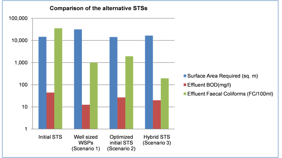
Figure 2. Comparison of alternative STSs in terms of surface area and treatment performances.
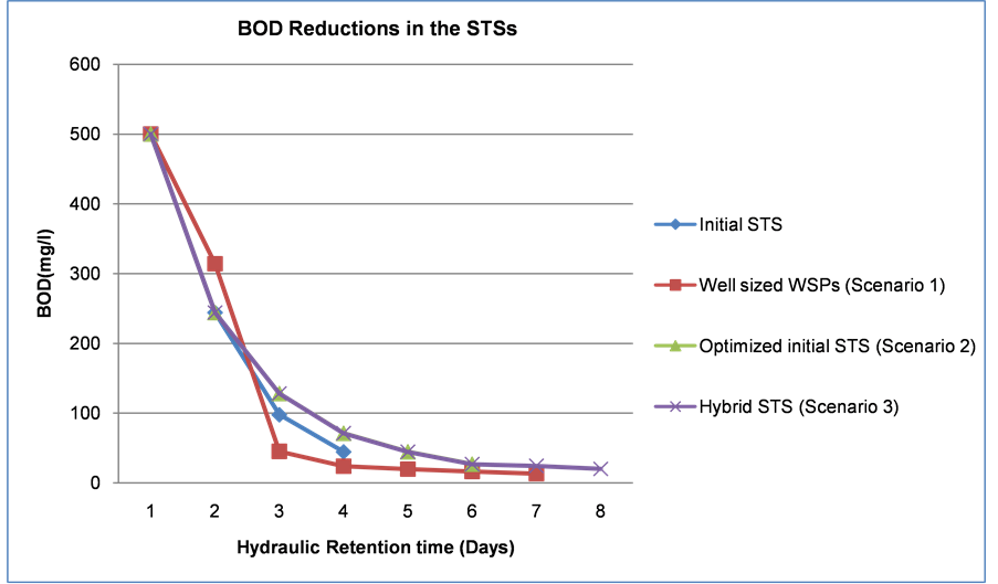
Figure 3. Comparison of BOD reduction in the alternative STSs.

Figure 4. Comparison of faecal coliform reduction in the alternative STSs.
satisfactory treatment performances include well sized WSPs (Scenario 1) and the hybrid STS (Scenario 3). The only limitation with scenario 1 was the large amount of land required. Thus, the hybrid STS was considered appropriate for wastewater treatment in the estate both in terms of land area required and projected treatment performance.
5. Conclusion
Based on this study, the objective of selecting a hybrid sewage treatment system for wastewater treatment in the housing estate demonstrated excellent wastewater purification performance in both BOD reduction and faecal coliform removal within the available land area in the housing estate. The incorporation of a constructed wetland in the hybrid system reduced the overall land area required for treatment by approximately half that was required for well sized WSPs. The treated effluent discharge from the hybrid STS with a BOD of 20 mg/l and 195 FC per 100 ml was acceptable for unrestricted crop irrigation and thus would be reused in the housing estate for kitchen gardening and agroforestry.
Cite this paper
Kogo, B.K., Biamah, E.K. and Langat, P.K. (2017) Optimized Design of a Hybrid Biological Sewage Treatment System for Domestic Wastewater Supply. Journal of Geoscience and Environment Protection, 5, 14-29. https://doi.org/10.4236/gep.2017.55002
References
- 1. WHO (2004) Development Goals: Sanitation Target Out of Reach for Many Countries. Bulletin of the World Health Organization, World Health Organization, Geneva.
- 2. Viessman, W. and Hammer, M.J. (1993) Water Supply and Pollution Control. 5th Edition, Harper Collins College Publishers, New York.
- 3. Chara, J., Pedraze, G. and Conde, N. (1999) The Productive Decontamination System: A Tool for Protecting Water Resources in the Tropics. Livestock Research and Rural Development, 11, 25-35.
- 4. Eckenfelder Jr., W.W. (1989) Industrial Wastewater Pollution Control. McGraw-Hill, New York.
- 5. United Nations Environment Program (UNEP) (1999) UNEP/Global Program of Action Strategic Action Plan to Address Sewage as a Major Land-Based Pollutant. UNEP Second Global Meeting of Regional Seas Conventions and Action Plans, Hague.
- 6. Wright, A. (1999) Toward a Strategic Sanitation Approach: Improving Sustainability in Developing Countries.
- 7. Lier, J.B. and Lettinga, G. (1999) Appropriate Technologies for Effective Management of Industrial and Domestic Wastewaters: The Decentralized Approach. Water Science and Technology, 40, 171-184.
- 8. British Broadcasting Corporation (BBC) (2004) Sanitation in Developing Countries.
- 9. Barongo and Mathu (2002) Ground Water Survey Report for Kaputuei, Kajiado-Kenya.
- 10. Mara, D.D. and Pearson, H.W. (1986) Artificial Freshwater Environments: Waste Stabilization Ponds. In: Schoenborn, W., Ed., Biotechnology, Vol. 8, 177-206.
- 11. Mara, D.D. and Pearson, H.W. (1998) Waste Stabilization Ponds: Design Manual for Mediterranean Europe. Lagoon Technology International Ltd., Leeds.
- 12. WHO (1993) Guidelines for Drinking-Water Quality. 2 Edition, World Health Organization, Geneva and HMSO, London.
- 13. Mara, D.D., Pearson, H.W., Alabaster, G.P. and Mills, S.W. (1997) An Evaluation of Waste Stabilization Ponds in Kenya. The Research Monograph No. 11, University of Leeds, Department of Civil Engineering, Leeds.
- 14. Mara, D.D., Pearson, H.W., Oragui, J.I., Arridge, H. and Silva, S.A. (1997) Development of a New Approach to Waste Stabilization Pond Design. The Research Monograph No. 5, University of Leeds, Department of Civil Engineering, Leeds.
- 15. Mara, D.D. (1986) Sewage Treatment in Hot Climates. John Wiley & Sons Ltd., Chichester, West Sussex, UK.
- 16. Von Sperling, M. (1999) Performance Evaluation and Mathematical Modelling of Coliform Die-Off in Tropical and Subtropical Waste Stabilization Ponds. Water Science and Technology, 33, 1435-1448.
- 17. Marais, G.V.R and Shaw, V.A. (1961) A Rational Theory for the Design of Sewage Stabilization Ponds in Central and South Africa. Transactions of the South African Institute of Civil Engineers, 3, 205-227.
- 18. Marais, G.V.R. (1974) Faecal Bacteria Kinetics in Waste Stabilization Ponds. Journal of the Environmental Engineering Division, 100, 119-139.
- 19. Mara, D.D. (1997) Design Manual for Waste Stabilization Ponds in India. Lagoon Technology International Ltd., Leeds, England.
- 20. Mara, D.D. (1998) Proposed Design for Oxidation Ponds in Hot Climates. Journal ASCE-EE, 101, 296-300.
- 21. EPA (1983) Design Manual: Municipal Wastewater Stabilization Ponds. Report No. EPA-25/1-83-015, Environmental Protection Agency, Municipal Environmental Research Information, Cincinnati, OH, 122.
- 22. O’Hagan, S. (2003) The Design, Operation and Performance of a Municipal Hybrid Reed Bed Treatment. Water Science & Technology, 48, 119-126.
- 23. Reed, S.C., Crites, R.W. and Middlebrooks, E.J. (1995) Natural Systems for Waste Management and Treatment. 2nd Edition, McGraw Hill, New York.
- 24. World Bank Water and Sanitation Program, Washington DC.
- 25. Meiring, P.G., Drews, R.J., van Eck, H. and Stander, G.J. (1998) A Guide to the Use of Pond Systems in South Africa for the Purification of Raw and Partially Treated Sewage.
- 26. Rausch, W.D. (2008) Design of a Pure Reedbed Sewage Treatment Plant (PURE-RSTS), the German Design of a Wastewater Management System.