Open Journal of Medical Imaging
Vol.4 No.2(2014), Article
ID:46553,8
pages
DOI:10.4236/ojmi.2014.42008
Physical Measurements for the Accuracy of Cone-Beam CT in Dental Radiography
Wed I. Shaibah1, Ibrahim A. Yamany2, Saddig D. Jastaniah1
1Diagnostic Radiology Department, King Abdulaziz University, Jeddah, Saudia Arabia
2Basic Oral and Clinical Sciences Department, King Abdulaziz University, Jeddah, Saudia Arabia
Email: sjastaniah@kau.edu.sa
Copyright © 2014 by authors and Scientific Research Publishing Inc.
This work is licensed under the Creative Commons Attribution International License (CC BY).
http://creativecommons.org/licenses/by/4.0/


Received 8 April 2014; revised 8 May 2014; accepted 22 May 2014
ABSTRACT
The introduction of cone-beam computed tomography (CBCT) for the maxillofacial imaging provided opportunities for dental practitioners to request multiplanar imaging. Currently CBCT is used during implant treatment-planning to measure accurately the height of bone available for implant placement to avoid serious problems e.g. compromising vital structure such as the inferior alveolar nerve during placement of implants. We present a physical method to assess the accuracy of measurements obtained from an i-CAT CBCT dental radiography unit used at king abdulaziz university hospital and to appraise the effect of voxel size on the accuracy of measurement by an i-CAT CBCT unit. Not significant difference was found between the physical and CBCT measurements for all the samples. The maximum measurements variation was + or −0.15 mm. Therefore, the linear measurements from i-CAT CBCT unit are accurate and the adjustment of the scan parameters like the FOV and voxel size will not significantly affect this accuracy.
Keywords:Maxillofacial Imaging, CBCT, Implant Placement

1. Introduction
Radiology is an integral part of dental practice. With the development of X-ray computed tomography (CT) in the 1960s, radiological tomography attained widespread use and today it’s one of the most essential imaging techniques in medical radiology. It is a technically mature and clinically widely accepted method and complements traditional radiology in many areas [1] .
Cone-beam CT scanners utilize a two-dimensional detector which allows for a single rotation of the gantry to generate a scan of the entire region of interest, as compared to conventional CT scanners where multiple “slices” are stacked to obtain a complete image. The fan-beam approach requires reconstructing the object slice-by-slice and then stacking the slices to obtain a 3D representation of the object. Each individual slice requires a separate scan and separate 2D reconstruction. The cone beam technique, on the other hand, requires only a single scan to capture the entire object with a cone shaped of X-ray beam. Thus, the time required to acquire a single conebeam projection is the same as that required by a single fan-beam projection. But since it takes several fan beam scans to complete the imaging of a single object, the acquisition time for the fan beam tends to be much longer than with the cone beam. Although it may be possible to reduce the acquisition time of the fan beam method by using a higher power X-ray tube, this increases the cost and size of the scanner as well as the electric power consumption, thus making the design unsuitable for a compact scanner. Although CBCT has existed for over two decades, its true potential has not yet been fully tapped [2] . Because CBCT exposure incorporates the entire FOV, only one rotational sequence of the gantry is necessary to acquire enough data for image reconstruction [3] .
Dentists use multiple radiographic techniques for diagnosable dental diseases and planning treatments. The use of Cone-beam computed tomography (CBCT) in clinical practice provides a number of potential advantages for maxillofacial imaging compared with conventional CT. Some of these advantages include the capability of CBCT units when adjusted to scan small regions for specific diagnostic tasks, all CBCT units provide voxel resolutions that are isotropic, scan time is rapid (10 - 70 seconds) and comparable with that of medical spiral MDCT systems. Published reports indicate that the effective dose of radiation is significantly reduced by up to 98% compared with “conventional” fan-beam CT systems, and an optimum FOV can be selected for each patient based on suspected disease presentation and region of interest [4] [5] . One of the major advantages of CBCT is its ability to define the true position of the condyle in the fossa, which often reveals possible dislocation of the disk in the joint, and the extent of translation of the condyle in the fossa and the measurements of the roof of the glenoid fossa can be done easily [6] .
While there has been enormous interest, current CBCT technology has limitations related to the “cone beam” projection geometry, detector sensitivity and contrast resolution. These parameters create an inherent image “noise” that reduces image clarity. Current systems are unable to record soft tissue contrast at the relatively low dosages applied for maxillofacial imaging. Another factor that impairs CBCT image quality is image artifact such as streaking, shading, rings and distortion. Streaking and shading artifacts due to high areas of attenuation (such as metallic restorations) and inherent spatial resolution may limit adequate visualization of structures in the dento-alveolar region [7] [8] .
CBCT technology provided opportunity for dental practitioners to request multiplanar imaging. Currently, CBCT is often used during implant treatment-planning to measure accurately the height of bone available for implant placement to avoid a serious problem i.e. compromising vital structure such as the inferior alveolar nerve during placement of implants.
There are numerous applications for CBCT in dentistry because this technology far surpasses film or 2D digital radiology in giving diagnostic information of the dental or maxillofacial regions. The amount of information one can obtain from a 3D image over a 2D image is considerable [9] .
Many studies have indicated the use of CBCT in dentistry for multiple diagnostic and treatment tasks. Examples of the uses of CBCT in dentistry include diagnosis of pathology, temporomandibular joint (TMJ) evaluation, orthodontic and implant treatment planning. During implant treatment-planning, evaluation of available bone is very important for successful treatment. It’s essential to measure accurately the height of bone available for implant placement to avoid compromising vital structure such as the inferior alveolar nerve or maxillary sinus during placement of implants [10] .
With increased demand for replacing missing teeth with dental implants, accurate measurements are needed to avoid damage to vital structures. This was achievable with conventional CT. However, with CBCT giving more accurate measurements at lower dosages, it is the preferred option in implants dentistry today. CBCT enables the assessment of bone quality and bone quantity. This leads to reduced implant failure, as case selection can be based on much more reliable information. This advantage is also used for post-treatment evaluation and to assess the success of bone grafts [6] [11] [12] .
Normal anatomy of the jaws and visible structures was described [13] . The tooth generally consists mainly of dentin, which has a radiologic opacity similar to cortical bone. In the region of the crown, a thin layer of enamel, which has by far highest opacity of all natural tissues, surrounds the dentin. The root canal is a centrally located, hypodense structure that is large in the crown region and decreases in size toward the direction of the root tip. A thin layer of cementum, which cannot be differentiated radiographically, surrounds the root dentin. The tooth in the region of the root is surrounded by the narrow periodontal space, which is hardly visible on CT. A widened, clearly visible periodontal space is typically indicative of pathology.
A section of a mandibular molar was illustrated in some references [14] [15] ; showing periodontal ligaments, group fibers of alveolar crest, horizontal, oblique, apical, interradicular and interdental.
A panoramic radiograph revealing well-defined, fusiform radiolucency in the area of left mandibular canal was previously reported [16] .
In this work, we evaluated the accuracy of the i-CAT CBCT unit and studied the effect of different adjustment parameters to help to develop standards for imaging patients in dentistry. We became motivated after receiving some doubts from dentist that the CBCT images did not reflect the actual sizes during implant surgeries. Thus, the aim of this study was to evaluate the accuracy of measurements from i-CAT CBCT Dental radiography unit and to appraise the effect of voxel size on the accuracy of measurement by on i-CAT CBCT unit.
2. Methodology
This study was done in the departments of diagnostic radiology at the faculty of applied medical sciences in combination with King Abdulaziz University Dental Hospital, Jeddah. The ethical approval was obtained from the hospital. We started testing the accuracy of measurements using Gutta percha and compared physical measurements with CBCT measurements in order to ensure the accuracy of this medical imaging modality in dental applications. The work also extended to appraise the effect of voxel size on the accuracy of measurement by i-CAT CBCT unit.
2.1. Materials
The imaging device used was i-CAT Next Generation by Imaging Sciences International and the software was CAT Vision 1.9. A Human skull from anatomy department in medical college was used to simulate the actual patient head. For physical measurements Gutta Percha i.e. a pure form gutta percha which is derived from latex as an isomer of rubber known as trnas-polyisoprene was used. It’s less elastic and harder than natural rubber [17] . In order to measure the gutta percha, a Vernier Caliper gives a direct reading of the length measured with high accuracy and precision. Vernier calipers commonly used in industry provide a precision to 0.01 mm [18] .
The skull was placed in a water container during CBCT image acquisition. The water bath container is made up of clear plastic and is 25 × 40 cm, which can accommodate the size of one skull. This was done to simulate the soft tissue surrounding the skull in regular patients.
Gutta Percha were cut in different lengths randomly and measured using a vernier calipers and placed vertically in the mandibular lingual surface of the dry skull and then placed in the water bath as shown in Figure 1. Other possible positioning of Gutta Percha may apply for different viewing in the sagittal reconstruction e.g. horizontally as presented in the results.
Different sizes of Gutta perch where characterized by normal distribution curve, starting from 2 mm as minimum and up to 30 mm to represent typical values of sizes used by dentist as shown in Figure 2.
2.2. Experiment Setup
Water bath was carefully centered in the field of view using the CBCT positioning guides. Subsequently each scan was given a code that only was known by the moderator of the study and was unknown to the image interpreter—oral and maxillofacial (OMF) radiologist.
For acquisition, each Gutta Percha was imaged three times with different resolutions using a standard departmental protocol as demonstrated in Table1
2.3. Image Interpretations
The acquired images were then sent to oral and maxillofacial radiologist for image interpretations. Images were read using i-CAT vision software in the oral radiology reading room at the usual oral radiology clinic viewing condition. Measurements of the imaged Gutta Percha were gained in the corrected sagittal view to guarantee that full length of the gutta percha is measured.
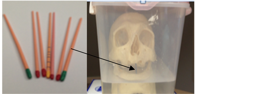
Figure 1. Gutta percha (left) and skull in water bath (right) after placing gutta percha.
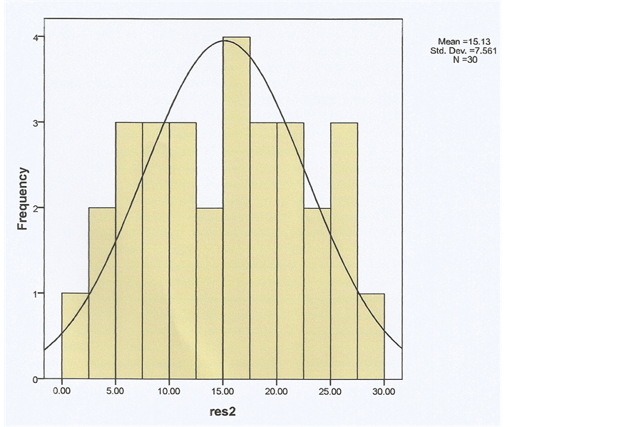
Figure 2. Different sizes of Gutta Perch characterized by normal distribution curve in order to ensure coverage of all possible lengths typically used by dentists.

Table 1. Acquisition parameters.
3. Statistical Analysis
Results obtained subjected to statistical analysis in order to calculate the common statistical data for each Gutta Percha size using SPSS program version 16.
4. Results
A sample size of 90 measurements was performed using variable lengths (L) of Gutta Percha with three different resolution as listed in Table2 The values indicates consistency of physical measurements with the measurements obtained by the imaging device i.e. non significant variation between L and CBCT measurements for all the samples.
The maximum intensity projection is shown in Figure 3, discriminating between the immersed part of the skull and the upper part.
Table 2. The actual lengths of Gutta Perch (L) measured by a vernier caliper, compared to lengths obtained from CBCT images at different resolution values (025, 0.3 and 0.4).
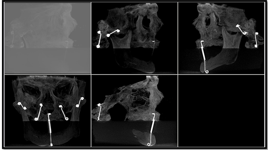
Figure 3. Maximum intensity projection (MIP), which clearly demonstrates the upper and lower parts of the skull immersed in the water and the wires holding the jaws.
The Axial view showing gutta percha on the lingual surface is demonstrated in Figure 4. The information in this image is used to determine the size the angle of the gutta percha. An example of this measurement is shown in Figure 5 of an axial view, where the yellow line demonstrates the angulation of the corrected sagittal slice used for measuring the gutta percha. Measurements of the imaged Gutta Percha were gained in the corrected sagittal view as shown in Figure 6 where a corrected sagittal slice is taken to demonstrate the method of gutta percha length measurement.
It is illustrated from the above table that the c2 of the 0.3 resolution was the smallest value. So, we can consider this resolution comparing with other resolutions. On the other hand, we can find that the one-tailed (righttail) probability value for a chi-square test of the 0.3 resolution was the biggest (i.e., the area under the chisquare distribution from the chi-square value to positive infinity).
5. Discussions & Conclusion
The difference between physical measurements and the CBCT measurements is minimal. In addition, the variations in measurements in different fields of view or relevant resolutions are not significant, with a maximum difference of +0.15 mm for all gutta percha sizes. The minimal variability in measurements might be due to factors related to the dentist daily procedures. These factors might include variability during dentist measurement i.e. the tracing measurement line is not placed accurately on the margins of the measured gutta percha. A second factor might be due to the resolution setting, since pixel size is different with variable field of view even though this variability is very minimal that will not affect the treatment planning procedures. A third factor may be due to the angulation of the CBCT slice where the gutta percha was measured, since it might not be matched with the gutta percha angulation.
The need for precise measurements in dental implants is very important in treatment planning. However, the gained measurements should hugely not affect the treatment planning if the error was less than 1 mm. The continuous comment about the accuracy of CBCT measurements is against the result of this study which proved the opposite. These claimed errors might be due to lack of experience and training in using CBCT in most dental practitioners. The CBCT introduced the third dimension into dentistry, which was new addition and improvement in dental practice. The European guidelines for using CBCT indicate that interpretation of CBCT should be done by trained dentist or by oral and maxillofacial radiologist [19] .
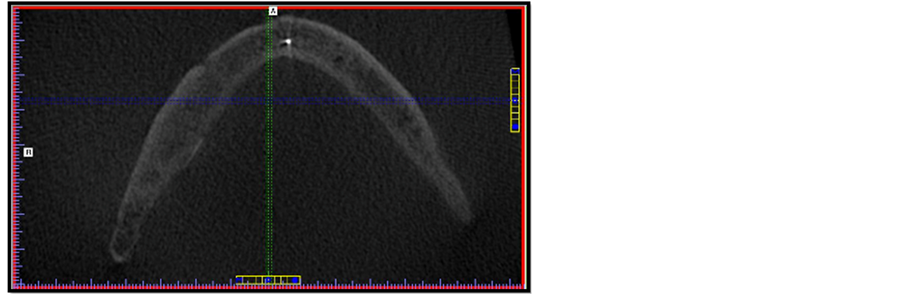
Figure 4. Axial view showing gutta percha on the lingual surface. The gutta percha in the left side is used to determine the size of the angle of the gutta percha.
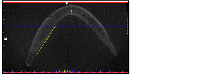
Figure 5. Axial view. Yellow line demonstrates the angulation of the corrected sagittal slice used for measuring the gutta percha.
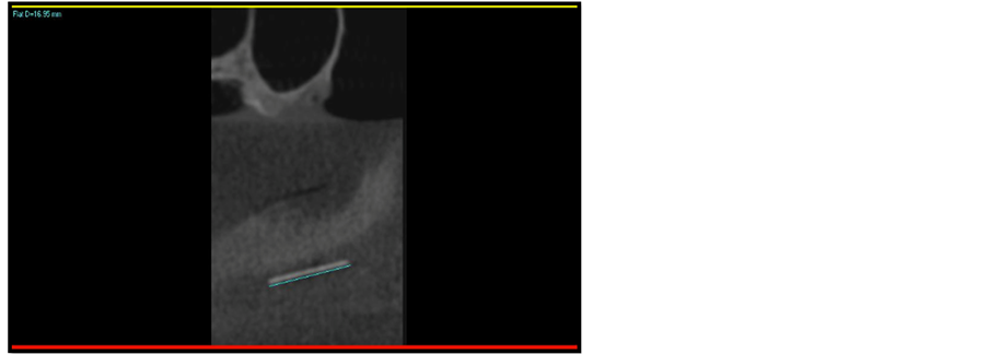
Figure 6. Corrected sagittal slice allowing to measure the gutta percha in a full length.
6. Recommendation
As the performed measurement method showed not significant variation from the measurements obtained by CBCT imaging, therefore it is highly recommended to perform such experiment at the time a quality assurance protocol is conducted, and to select a real skull to ensure simulation to the real patient and use a digital caliper with 0.1 mm sensitivity at most.
References
- Zoller, J.E. and Neugebauer, J. (2008) Fundamental of Cone-Beam Volumetric Imaging Technology. In: Cone-Beam Volumetric Imaging in Dental, Oral and Maxillofacial Medicine: Fundamentals, Diagnostics, and Treatment Planning, Quintessence Publishing Company Limited, New Malden, 22-23.
- Sukovic, P. (2004) Cone Beam Computed Tomography in Dentomaxillofacial Imaging. American Association of Dental Maxillofacial Radiographic Technicians, from the Winter 2004 AADMRT Newsletter.
- Scarfe, W. and Farman, A. (2008) What Is Cone-Beam CT and How Does It Work? Dental Clinics of North America, 52, 707-730. http://dx.doi.org/10.1016/j.cden.2008.05.005
- Scarfe, W., Farman, A. and Sukovic, P. (2006) Clinical Applications of Cone-Beam Computed Tomography in Dental Practice. Journal of the Canadian Dental Association, 72, 75-80.
- Scarfe, W. and Farman, A. (2007) Cone Beam Computed Tomography: A Paradigm Shift for Clinical Dentistry. Australasian Dental Practice, July/August, 108-104.
- Alshehri, M.A., Alamri, H.M. and Alshalhoob, M.A. (2012) CBCT Applications in Dental Practice. General Dentistry, 60, 390-400; quiz 401-402.
- Ibraheem, I. (2012) Reduction of Artifacts in Dental Cone Beam CT Images to Improve the Three Dimensional Image Reconstruction. Journal of Biomedical Science and Engineering, 5, 409-415. http://dx.doi.org/10.4236/jbise.2012.58052
- Jaju, P.P., Jain, M., Singh, A. and Gupta, A. (2013) Artefacts in Cone Beam CT. Open Journal of Stomatology, 3, 292-297. http://dx.doi.org/10.4236/ojst.2013.35049
- Levato, C., Farman, A., Chenin, D. and Scarfe, W. (2009) Cone-Beam Computed Tomography: A Clinician’s Perspective. Inside Dentistry, 5, 66-73.
- Ganguly, R. (2009) Accuracy of Linear Measurement in Galileos Cone-Beam CT under Simulated Clinical Condition. Master’s Thesis, University of Iowa, Iowa City.
- Mills, E.J. (2013) CBCT and Implants: Improving Patient Care, One Implant at a Time, Part I. The Dentistry iQ Network. http://www.dentaleconomics.com/articles/print/volume-101/issue-4/features/cbct-and-implants-improving-patient-care-one-implant-at-a-time-part-1.html
- Roth, J.S. (2011) CBCT Technology: Endodontics and Beyond, Part 2. Dentistry Today, Monday, 7 March 2011. http://www.dentistrytoday.com/endodontics/4731-cbct-technology-endodontics-and-beyond-part-2
- Nelson, S.J. (2009) Introduction to Dental Anatomy. In: Wheeler’s Dental Anatomy, Physiology, and Occlusion, 9th Edition, Saunders Elsevier, St. Louis, 18-29.
- Phinney, D.J. and Halstead, J.H. (2004) Embryology and Histology. In: Delmar’s Dental Assisting: A Comprehensive Approach, 2nd Edition, Cengage Learning, Boston, 89-100.
- http://www.dentistry.unc.edu/NRA/PanAnatomy/skull_images/mandibular-canal-s.html
- Vartiainen, V., Siponen, M., Roseberg, J. and Apaja-Sarkkinen, M. (2008) Widening of the Inferior Alveolar Canal: A Case Report with Atypical Lymphocytic Infiltration of the Nerve. Oral Surgery, Oral Medicine, Oral Pathology, Oral Radiology, and Endodontology, 106, e35-e39.
- McCabe, J.F. and Walls, A.W.G. (2008) Endodontic Materials. In: Applied Dental Materials, 9th Edition, WileyBlackwell, Hoboken, 289-294.
- I-CAT CBCT Measurements. http://en.wikipedia.org/wiki/Vernier_caliper#Vernier_caliper
- http://www.sedentexct.eu/content/guidelines-cbct-dental-and-maxillofacial-radiology