Modern Instrumentation
Vol.2 No.1(2013), Article ID:27453,9 pages DOI:10.4236/mi.2013.21002
Toward a Test Protocol for Conducted Energy Weapons
1Department of Systems and Computer Engineering, Carleton University, Ottawa, Canada
2Datrend Systems Inc., Vancouver, Canada
3Vernac Ltd., Ottawa, Canada
4MPB Technologies, Montreal, Canada
Email: adler@sce.carleton.ca
Received November 4, 2012; revised December 9, 2012; accepted December 18, 2012
Keywords: Conducted Energy Weapons; Electrical Stimulation; Electrophysiological Standards
ABSTRACT
Conducted Energy Weapons (CEWs), such as those manufactured by TASER International Inc., are seeing increased use by law enforcement agencies as a less lethal force option; but, at the same time, these weapons are also seeing an increased level of concern in terms of their safety of use. In order to enable consistent evaluation of CEW performance, a systematic protocol for testing the electrical output of such weapons is required. In this paper, we propose a test specification for CEWs, designed to calculate the key performance and electrical safety parameters. The weapon is fired into a specified load, and current or voltage data are acquired, from which a set of electrical parameters are calculated and recorded. The protocol is based on experience of testing 6000 CEWs in the labs affiliated with the authors. This test protocol is designed to enable systematic testing, evaluation and research on CEW’s, including identification of weapons which are out of specification, determination of changes in weapon characteristics over time, and evaluation of weapons post-incident. Based on the proposed test protocol, we evaluate and report on electrical output produced by 208 X26™ and 128 M26™ TASERÒ weapons. Results are shown in terms of proposed summary parameters and in terms of manufacturer’s performance specifications.
1. Introduction
Conducted Energy Weapons (CEWs) are increasingly used by police in many countries as a less-lethal force option. The most widely used CEWs are the M26™ and X26™ models from TASER International Inc. (TI), which work by firing two small darts (electrodes) attached to wires into the subject. The weapon then sends a pulsatile electrical current into the subject, designed to be sufficiently rapid and with enough energy to cause muscular incapacitation [1]. This incapacitation is intended to give an arresting officer time to gain control over the subject. There has been increasing public concern over the safety of CEWs, and there have been a number of widely publicized deaths subsequent to CEW use. To help clarify the issues, a number of authors have performed investigations of CEW safety. The main experimental research involves prospective experiments on anesthetized animals [2-5] and on healthy human volunteers [6-8]. Other research has analyzed reports from police, coroners, medical case reports and computer models of current flow in the body [9-12].
Overall, the current literature has suggested that risks are relatively low to healthy subjects from short duration CEW pulses of the standard stimulation strength of inuse devices. In general, either stronger or significantly longer electrical stimulation [2,4], or stimulation close to the heart [12] was required to induce clinically significant effects to cardiac or respiratory function or blood chemistry. Studies of case reports showed that the injury profile of CEWs is similar in comparison to other lesslethal force options, such as physical restraint or pepper spray [9,10], although one case report shows ventricular fibrillation in a healthy subject [13]. For longer or multiple stimulations, CEWs were shown to have significant physiological effects on cardiac, respiratory and blood chemical function, which led to death in some animals [14,15]. Such effects could interact with events during an arrest (stress, intoxicants, restraint, and blood loss). Specific subject groups such as the elderly, children, pregnant women, and cardiac device users may have higher risks [16]. Additionally, there are clear risks to vulnerable organs from penetration by the electrode barbs, and due to falls consequent to incapacitation [17]. The current literature is limited by the fact that experimental research has focused on healthy pigs and human volunteers, while deaths proximal to CEW use are most likely in unhealthy, intoxicated, and highly stressed subjects, including those with excited delirium. Tests of several hundred healthy subjects have been reported in the literature [3-5]; however, CEW-associated deaths have occurred in less than one in a thousand weapon usages, and computer models estimate similarly low risk levels [9- 11]. To reliably investigate such rare events, much larger studies are required.
In addition to such research on the effects of CEWs, an important requirement for systematic and repeatable testing of CEWs has been identified. In Canada, an inquiry recommended that governments implement periodic testing of police CEWs [18]. Such testing is required to ensure that weapons continue to function properly, and can be repaired or withdrawn if they do not. For forensic studies (after an incident with a CEW), test records would help determine whether the weapon was functioning properly.
In this paper, we propose a standard method for testing of CEWs, and then make tests of weapons according to this method and report the results. The goal of the proposed CEW Test Procedure is to recommend a methodology to determine whether the weapon under test is operating within manufacturers’ specifications, as well as to define data collection requirements so that data collected during the testing of any CEW may be used for future research and data mining programs. There are several challenges in creating a test standard for CEWs, such as the fact that safety research is ongoing and thus our current knowledge of safety limits is provisional. However, there is an urgent need to begin systematic testing, which motivates us to do our best to propose a standard approach for investigation to follow.
The paper is structured as follows: First, we develop a standard for testing of CEWs, and then based on the proposed test protocol; we evaluate and report on electrical output from 208 X26™ and 128 M26™ TASERâ weapons. Results are shown in terms of proposed summary parameters and in terms of performance specifications.
2. CEW Characteristics
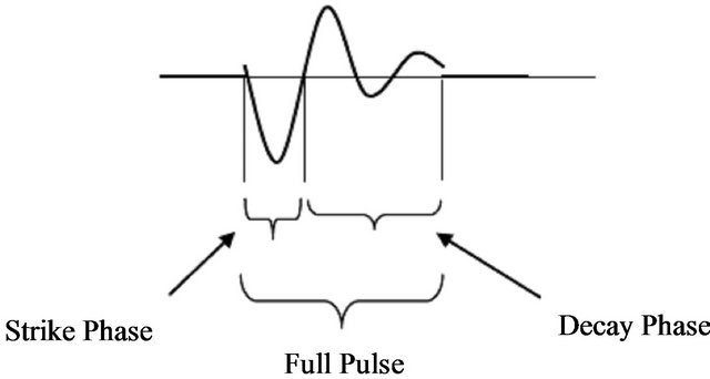
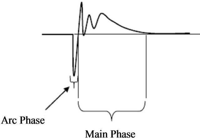
This section provides general details on the waveform, definitions and specifications of the parameters of interest describing the pulse generated by CEW. In general, the electrical output of a CEW comprises a number of discrete pulses which are delivered for a preset duration, which is designated herein as the “burst length” (Figure 1) Examples of M26 and X26 pulses are shown in Figure 2. The pulse generated by a M26 consists of a damped oscillation where the initial half sinusoid is known as the “Strike phase” and the second half as the “Main phase” (Figure 2(a)). The X26 pulse is composed of “Arc” and “Main” phases respectively, per Figure 2(b).
2.1. CEW Waveforms
Specific details of the TASER M26 and X26 pulse waveforms are shown in Figures 3 and 4 respectively. Referring to Figure 3, a single pulse output by a M26 consists of a damped oscillation with a 17-microsecond (µs) time constant. The M26 waveform comprises two segments, defined as the “Strike” phase and “Main” phase respectively. M26 pulses are delivered in a cycle or “burst” which consists of approximately 75 pulses over 5 seconds, equivalent to a rate of 15 pulses per second, if an alkaline battery is used. If a NiMH battery is used, the M26 may generate up to 26 pulses per second. For the M26, the Strike phase is approximately 10 µs in duration , and delivers about 100 microcoulombs (µC) of electric charge in a single direction, whereas the remainder of the pulse delivers about 100 µC spread over 40 µs in alternating negative and positive directions. The Strike
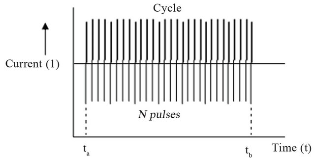
Figure 1. Example of TASER pulse burst (i.e. cycle) consisting of approximately 75 - 100 pulses over 5 seconds.
(a)
(b)
Figure 2. Diagram of a TASER Pulse consisting of: (a) Strike and Decay phases for the TASER M26; (b) Arc and Main phases for the TASER X26, respectively.
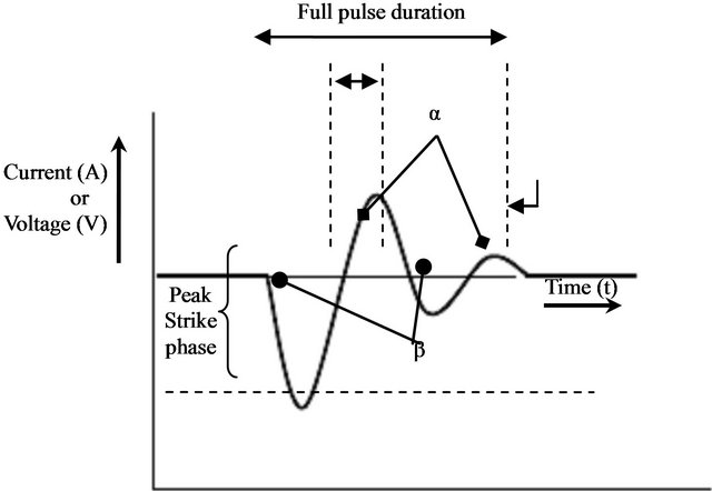
Figure 3. M26 pulse waveform showing: 1) Peak value (voltage or current), defined only for the Strike phase; 2) Net charge calculated as the absolute value of area under the current waveform in the Strike phase (βS); 3) Full pulse duration starting at an initial crossing of ±150 V and finishing when pulse decreases to ±225 V; 4) Monophasic Charge calculated as the maximum of absolute values of α and β; 5) Total charge computed as the sum of the absolute values of α and β where α = integral of positive current in pulse waveform and β = integral of negative current in pulse waveform.
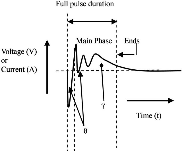
Figure 4. X26 pulse waveform showing: 1) Peak value (voltage or current), defined only for the waveform main phase; 2) Net charge calculated as the absolute value of area under the current curve in the Main phase (γ); 3) Full pulse duration starting at an initial crossing of ±50 V and finishing when pulse decreases to ±50 V; 4) Monophasic Charge calculated as the maximum of absolute values of γ and θ; 5) Total charge computed as the sum of the absolute values of γ and θ where γ = integral of positive current in pulse waveform and θ = integral of negative current in pulse waveform.
phase may be observed either above or below the time axis, which is directly related to the way the load is connected to the scope according to polarity of the connection between the load and data acquisition system. Whether an inverted or non-inverted waveform is observed, parametric definitions and methods of signal analysis are the same.
For the X26, a single pulse consists of an “Arc phase” and “Main phase” as shown in Figure 2. The pulses are delivered in a cycle or “burst” consisting of approximately 95 pulses over 5 seconds, corresponding to a rate of 19 pulses per second. In an X26 pulse waveform, most of the electric charge is primarily contained in the Main phase. The Main phase delivers about 100 µC of charge, whereas the arc phase has only 10 µC. The purpose of the arc phase is to create a conductive path to the target’s skin through an insulation barrier such as air or clothing, to allow efficient delivery of charge during the Main phase. The arc phase has a faster rise time and a higher peak than may be seen on some oscilloscopes, because of integrating effects in some voltage and current probes having bandwidth under 100 MHz.
Parameters in Table 1 are computed for M26 and X26 pulses and are used in the proposed Test Procedure to characterize weapon behavior, compare performance to manufacturer’s specifications, and develop provisional safety limits for each weapon.
3. Methods
In this section, we propose a CEW Test Procedure to evaluate the electrical performance of CEWs and define data collection requirements to facilitate performance analysis and future research. The goal of the proposed CEW Test Procedure is to: 1) establish a methodology, by which testing facilities and personnel can test CEWs and determine whether they are operating within manufacturers’ specifications; 2) define data collection requirements so that data collected during the testing of any CEW may be used in forensic analysis of that weapon and may also be added to a central database for future research and data mining programs. This Test Procedure is meant for use with Conducted Energy Weapons that have the following characteristics: 1) they are hand held; 2) they use a pulse or pulse train to deliver electrical energy to the target; 3) they are meant to function by causing temporary human electro-muscular incapacitation. In addition, we provide new definitions and specifications describing two different CEW models such as the TASER® M26 and X26, respectively. Parameters of interest are derived and calculated from the measurements and compared against manufacturer specifications to determine whether the weapon under test is operating within normative limits.
3.1. Test Apparatus
We propose a standard procedure for testing, analysis and reporting on the electrical output of a CEW, in accordance with the schematic in Figure 1. The CEW is connected to the test system, consisting of the weapon connection, a resistive load, a voltage or current probe
Table 1. Parameters computed using M26 and X26 pulse waveforms used in the proposed test procedure.
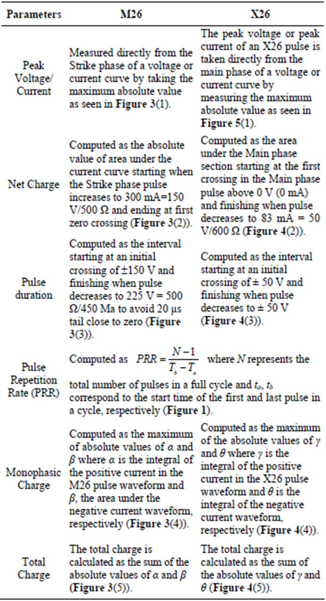
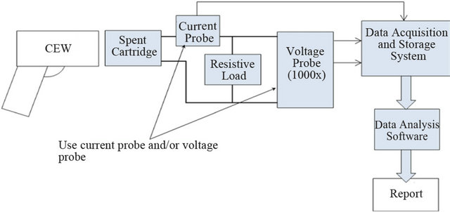
Figure 5. Schematic diagram of CEW test setup.
and data acquisition equipment. The weapon is fired into the load while data are acquired at a resolution and sampling rate designed to keep acquisition errors below 1%. Data are then analyzed to calculate the parameters related to CEW performance and safety. The procedure is structured as a main section on the general testing of CEWs, with appendices providing specific details for the two most common weapons in service (models M26 and X26 from TASER International Inc.). The Test Procedure is designed for routine (periodic) and post-incident inspecttion, and requires three 5-second firings of the weapon into the test load. If daily, pre-service, inspection is desired, a shorter test is recommended.
3.2. Test Equipment Requirements
This section describes the equipment required for the electrical testing of CEWs. It is suggested to calibrate all test equipment on a yearly basis to meet national standards. The CEW is connected to the test system, consisting of an interface to the weapon output terminals, a resistive load, a voltage or current probe, and data acquisition equipment. Data are acquired at a resolution and sampling rate designed to keep acquisition errors below 1% of the maximum specified voltage. A minimum bandwidth of 10 MHz and sampling rate of 10 MSamples/s are required. A voltage reduction probe (1000:1) with a minimum rating of 10 kV or a current probe suitable for ranges up to 30 A should be used. Per Appendix A, the load resistance will range from 500 - 600 Ω depending on the CEW model under test., and should have a rating of 10 W or greater. To preserve waveform fidelity, reactance in the signal path must be as low as practicable; this is achieved through use of film-type resistors for the load and short, large-diameter conductors for load connections. Finally, a jig or other mounting method is required to stabilize the weapon and allow hands-off operation during a test. The jig may employ a spent cartridge, although a mechanism which secures the weapon in place while providing an air gap of 1.5 millimeter at each output terminal will yield equivalent results. The test setup should be mounted on an insulating surface to ensure protection of users from electrical discharge.
3.3. Test Procedure
This procedure gives test setup, conduct and analysis methodology. Detailed procedures for different makes and models of test equipment have not been provided to allow testing organizations flexibility in choice of equipment. Good engineering practice, proper laboratory processes and familiarity with laboratory measurement equipment and protocols are assumed. Detailed quantitative data for determining compliance with manufacturer’s specifications are given in the appendix for specific models of CEW.
3.3.1. Inspection
Prior to beginning a test, record the following: 1) weapon manufacturer; 2) model number and Serial number; 3) battery model and serial number (if available without opening unit under test); 4) battery capacity (if available without opening unit under test); 5) software version installed (if available without opening unit under test); and 6) temperature, humidity and atmospheric pressure of the test environment.
3.3.2. Setup
During the measurement setup process, the test equipment is mounted on an insulating surface and the following are consecutively executed: 1) select a sampling rate of 10 M Samples/s or greater on the Data Acquisition System; 2) connect the probe(s) to the test apparatus: a) connect the high voltage probe across the test load; and/or b) place the current probe around the appropriate lead from the weapon to the load; 3) connect the probe leads to the Data Acquisition System; and 4) connect the weapon to the load using a spent cartridge or equivalent. It is important to note that repeated use of a spent cartridge may result in buildup of deposits due to arcing. For this reason, inspect and clean the cartridge regularly. Place the weapon in a test stand or equivalent, to reduce the need for direct handling during discharge.
3.3.3. Test
Collect the CEW data as follows: 1) pull then immediately release the trigger on the weapon to initiate a burst; 2) allow the weapon to discharge for the full duration of the burst (5 seconds), 3) verify that all data has been acquired and stored; 4) fire the weapon two more times and record the data; 5) verify data has been acquired and stored; and 6) identify the data records with the serial number of the weapon under test.
3.4. Data Analysis
Data analysis can be executed immediately following data acquisition using the data analysis software available under the open source license at [19]. The data analysis software calculates the Pulse Repetition Rate parameter using pulses that fall within the last second of the burst during the first firing of the weapon. The CEW data analysis software will also determine the following by averaging data from the last 8 pulses recorded for the second firing of the weapon: Peak Voltage, Peak Current, Net Charge and Pulse Duration.
These parameters are calculated to determine conformance of the weapon to manufacturer’s specifications. The outputs of the analysis software are compared to the manufacturer’s specifications given in the appendix in order to determine whether the weapon’s performance is: 1) above Tolerance; 2) in Tolerance or 3) below Tolerance. If all five parameters are in tolerance, then the weapon may be reported as having performed within manufacturer’s specifications. If a weapon performs Out of Tolerance, it is suggested, prior to additional testing, to replace the batteries or Digital Power Magazine (DPM) of the unit since this may cause the weapon to perform within tolerance. Note that for some weapons, introducetion of a new DPM may introduce new operating software, which may create a new configuration of the weapon. This procedure should only be carried out if prior agreement on this policy has been established with the owner of the weapon and, in any event, the testing procedure should be repeated on the new weapon/power system combination and reported as a separate test with a separate test report.
In addition to the five parameters described above, the analysis software will determine the Monophasic Charge (MC) and Total Charge (TC) for each pulse in each of the three firings of the weapon. CEWs with Monophasic Charge for any individual pulse in excess of the value listed in the corresponding appendix should be declared Out of Tolerance. Furthermore, the software will calculate and store, for each of the seven parameters (Pulse Repetition Rate, Peak Voltage, Peak Current, Net Charge, Pulse Duration, Monophasic Charge and Total Charge) the value for each pulse for each firing. In addition, the maximum, minimum and average of each parameter for all pulses in each of the three firings are calculated and stored. Note that the average pulse repetition rate is the pulse repetition rate for the burst length, and not the average of the pulse repetition rates for each pulse in the burst.
4. Test Methodology: Discussion
The previous section details our proposed test methodology. In this section, we review and discuss our reasoning behind the choices made. The specified electrical measurements described in section (Ⅲ) are designed to enable the following tests: 1) performance testing against manufacturer specifications; 2) measurement of the parameters which, as best we can determine, will be useful to test against safety limits developed by future electrophysiological research; 3) data gathering to allow statistical analysis of weapon behavior, such as determination of early indicators of failure. Thus this protocol includes, but goes beyond, the one proposed by TASER International [20]. It extends the recommended tests in that all pulses are measured and recorded and the maxima and minima calculated, while the manufacturer’s specifications are concerned with the average across pulses (and specifically the last eight pulses). This procedure recommends the calculation of a new pulse parameter which may be related to electrical safety standards for ventricular fibrillation. We note that the safety of CEW waveforms is related to several complex physiological processes, which are still poorly understood. We are able to recommend a safety threshold for fibrillation, since related safety standards exist; however, it is not currently possible to propose corresponding thresholds for other physiological risks. For this parameter, the most relevant specification is that of IEC60479 Part 2 [21] which considers the “effects of unidirectional single impulse currents of short durations” (0.1 ms and above). Section 11 of the specification defines curves based on the “probability of fibrillation risk for current flowing through the body from the left hand to both feet”. We base our calculation on the “C1 curve” which is defined as “no risk of fibrillation”. For currents above 500 µA, this curve may be fitted to a limit of 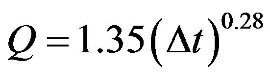 where Q is the charge threshold in µC, and Δt is the pulse duration in ms. Thus, IEC [21] considers the threshold to be mostly a function of the charge alone, with a small increase with pulse duration. If we consider the main current contribution from the CEW pulse to be approximately 0.1 ms, this is equivalent to a 710 µC charge limit (for comparison, if a pulse length of ∆t = 0.11 or 0.12 ms were used, the limit would be 728 or 746 µC, respectively.) To account for differences in body size and placement of stimulation electrodes, we recommend an additional safety factor of four to be imposed. Since CEW waveforms are not unidirectional, the tables of section 11 of IEC [21] do not apply exactly. Thus, we need to derive a parameter from the CEW discharge which may be compared to the standard. We considered the parameters Total Charge (TC), or Monophasic Charge (MC), where TC is the integral of the absolute value of current in a CEW pulse, and MC is the maximum of the integral of current in either direction in a pulse. TC is a more conservative measure; however, MC may be justified based on physiological models such as described in [22]. Based on our understanding of the current literature, MC is the appropriate measure and we recommend it as the appropriate safety limit for the threshold from IEC [21] for the waveforms of the TASER M26 and X26.
5. Experimental Procedure and Test Results
Extensive testing of CEWs has been conducted in the laboratories affiliated with the authors, using several equipment and workflow patterns conforming to the proposed methodology (Section Ⅲ). The foregoing sections described general procedures for testing CEWs. In this section, we describe the specific data acquisition system and data analysis software used at Carleton University to acquire and analyze signals from CEWs.
5.1. Experimental Procedure
Apparatus suitable for testing CEW electrical output has been specified in Section Ⅲ. Several different sets of equipment conforming to these requirements have been used in our laboratories. For example, some of the first generation acquisition systems consisted of National Instruments PXI-5122 and PXI-8186 in a PXI-1031 chassis. A Tektronix 6015 A reduction probe (1000:1) with a minimum of 10 kV rating is used to attenuate the voltage which is input to the test equipment. This test equipment configuration generates very large raw data files (27 MB) for a 5 second signal episode. Data are acquired at a resolution and sampling rate which results in acquisition errors of 0.4% for voltage and 0.1% for the time measurement. For the load setup, a resistance that ranges from 500 - 600 Ω is used depending on the CEW model under test. The mounting method consists of an expended cartridge mechanically fastened to the load and having identical electrical characteristics. The mount stabilizes the weapon and allows hands-off operation during test. Custom written software drives the PXI-8186 controller and PXI-5152 digitizer to acquire signal for a 7 seconds window during which 5 seconds of CEW emission are captured.
In a different configuration, the data acquisition equipment consisted of a Picoscope 4224 dual-channel 20 MHZ oscilloscope. Custom written software [23] drives the Picoscope to acquire the signal during periods when energy is present in a 5 second burst, as well as creates and manages data storage on the Dell laptop to which the Picoscope is connected via a USB interface. This test equipment configuration generates much more manageable raw data files in the order of 500 KB for a 5 second signal episode since raw data is captured only during periods when signal energy is present. A window of a 50 µs shoulder on either side of the 100 us energy period is also applied to ensure that we capture everything in the period when energy is present.
Using these configurations, a raw data file is then obtained and analyzed using Matlab to calculate, in addition to the manufacturer’s performance specifications, absolute minimum and maximum values for the voltage, current, charge, pulse duration as well as analyzing the pulse repetition frequency based on the entire pulse train. For a better visualization of the results, calculated values are presented in an HTML file in accordance with the format recommended in the Test Procedure.
5.2. Aggregated Test Results
Since 2009, Carleton University has been acquiring data from CEW testing both of its own accord and from other organizations. In 2011, data mining produced global results on population behaviour particularly with respect to numbers and types of out-of-tolerance conditions. For the M26 data analysis, data from 128 M26 weapons were used which involves 255 raw data files. For the X26 analysis, data was generated using 920 files most of which were generated as a result of Carleton University testing activities (Figures 6 and 7). As a side note, the M26 data were tested and obtained from MPB while the X26 units were tested as received. Data calculated during the tests mentioned above are tabulated below for the TASER M26 and X26 models, respectively.
Note that TASER International [20] also specifies Full Pulse Net Charge and Strike Phase Duration as parameters for the M26. It is believed that the Strike phase Charge and Full Pulse Duration are important parameters since they show smaller out-of-tolerance percentages for both M26 and X26 weapons, respectively. Table 2 shows a higher out-of-tolerance percentage for the M26 compared to the X26. It is seen that the most common outof-tolerance parameter is the pulse repetition rate, specifically occurring below 16.5 pulses per second as indicated in the manufacturer’s X26E performance specifica-
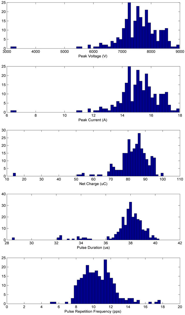
Figure 6. Histogram plots showing 5 main characteristics and parameter values such as (1) Peak Voltage; (2) Peak Current; (3) Net Charge; (4) Pulse Duration; (5) Pulse Repetition Frequency for the TASER M26 CEW.
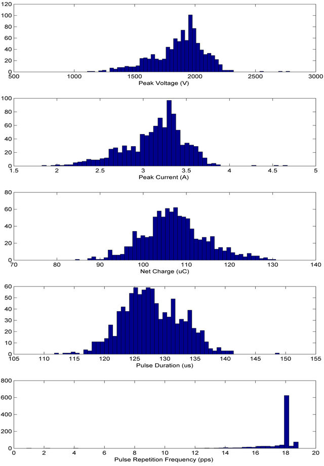
Figure 7. Histogram plots showing 5 main characteristics and parameter values such as (1) Peak Voltage; (2) Peak Current; (3) Net Charge; (4) Pulse Duration; (5) Pulse Repetition Frequency for the TASER X26 CEW.
Table 2. TASER M26 and X26 CEW operating parameters and values. Weapon samples were based on test requests from owners, and thus do not constitute a representative sample.
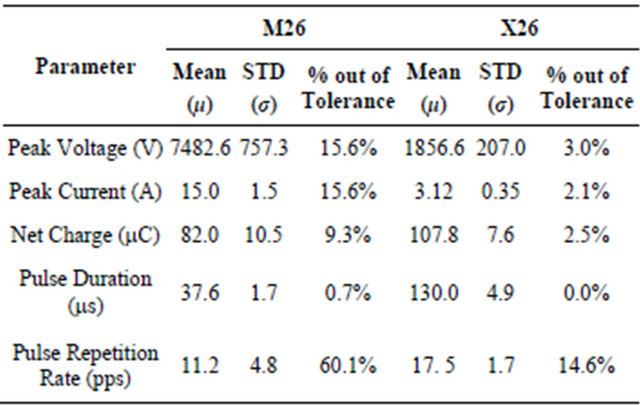
tions [20]. All other out-of-tolerance conditions occur at a much less significant rate compared to pulse repetition frequency.
Figures 6 and 7 show histogram plots illustrating five main parameter characteristics for the X26 and M26 CEW weapons, respectively. Using 920 X26 and 255 M26 raw data files, values are calculated for the following parameters: 1) Peak Voltage; 2) Peak Current; 3) Net Charge; 4) Pulse Duration; 5) Pulse Repetition Frequency, which also illustrate the average parameter distribution for each weapon, respectively.
6. Discussion
This paper proposes a protocol and standard for testing of the electrical performance of conducted energy weapons. We are motivated by the increased concern about the safety and effectiveness of these weapons and the need to understand how CEW’s perform over their life cycle. This Test Procedure will enable organizations to test CEWs in a reliable, repeatable manner to determine whether they are operating within manufacturers’ specifications. Test results so obtained will be usable in various ways: 1) the CEW inventory of a given police service can be tested on acceptance and regularly thereafter to ensure all issued weapons are functioning as intended; 2) any CEW involved in an incident resulting in personal injury will be able to be tested after the incident to reliably determine its operating parameters; 3) all data collected from weapons tests across multiple sites will be known to be reliable and comparable. This will enable the growing body of knowledge concerning CEW operation over time so that future research may be able to determine trends in age or other factor-related changes in performance.
Our Test Procedure has highlighted the need for regular and standardized testing of CEWs. It provides a way for independent and transparent testing without specifying particular equipment or organizations. Our proposed test protocol was developed by an ad-hoc group of subject matter experts, representing academic researchers, government scientists and companies involved in CEW testing. The laboratories associated with the authors have tested over 6000 CEWs. The initial framework for the standard was elaborated at a set of workshops held at Carleton University (May 2009 and May 2010). Requirements for the standard were established through discussions with police organizations, and Canadian federal and provincial police policy organizations. Several of the authors have previously discussed CEW testing with staff from TI, although the company was not involved in this document. None of the authors has any financial or personal interest with TI or any other CEW manufacturer. Although based on discussions with government organizations, our proposed protocol does not have any official status; it represents the collective recommendations of its authors. However, in order to enable it to be used as part of a policy document, if desired, we place it under a permissive copyright license (Creative Commons) [25].
Based on the proposed test protocol, we test, evaluate and report on electrical output from 208 X26 and 128 M26 TASER weapons. For our tests, we consider the test load recommended by TI (non-inductive loads of 600Ω and 500 Ω for the X26 and M26 weapons, respectively) to be an adequate model of the impedance load of the body. These CEWs behave largely as a current source and have relatively little variation in TC with load. Savard et al. [24] found a variation of approximately 25% from the average across loads below 1000 Ω. Such variation may be accommodated by the safety factor.
In summary, we propose a CEW test protocol based on our understanding of the current electrophysiological science of these weapons, in the hopes that it may be a contribution to public safety and security. Our Test Procedure shows results which contribute to life cycle management of CEWs and performance expectations over a large number of weapons and time.
7. Conclusion
This paper proposes a standard method for testing of conducted energy weapons. A new CEW Test Procedure is developed which establishes a methodology delivered to testing facilities and personnel in order to evaluate the performance of CEW in-use and define data collection requirements for further analysis. In addition, this paper provides details of the waveform, definitions and specifications of the TASER M26 and X26 models, respectively. Parameters of interest are derived and calculated from the measurements and compared against manufacturer specifications to determine whether the weapon under test is operating within specified limits. A detailed description of the Test Procedure and data analysis is also presented in this work. Finally, an example of data calculated during a typical test is shown for the TASER M26 and X26 models, respectively.
8. Acknowledgements
This Test Procedure was developed as a result of an initiative spearheaded by the, Systems and Computer Engineering Department, of Carleton University, who organized workshops on the topic of CEWs with partial funding from Public Safety Canada and the Canadian Police Research Centre (CPRC).
REFERENCES
- D. Panescu, R. A. Stratbucker, “Current Flow in the Human Body,” In: M. W. Kroll and J. D. Ho, Eds., Taser Conducted Electrical Weapons: Physiology, Pathology and the Law, Springer, Berlin, 2009. doi:10.1007/978-0-387-85475-5_6
- A. J. Dennis, D. J. Valentino, R. J. Walter, K. K. Nagy, J. Winners, F. Bokhari, D. E. Wiley, K. T. Joseph and R. R. Roberts, “Acute Effects of TASER X26 Discharges in a Swine Model,” Journal of Trauma Injury, Infection, and Critical Care, Vol. 63, No. 3, 2007, pp. 581-590. doi:10.1097/TA.0b013e3180683c16
- S. J. Holden, R. D. Sheridan, T. J. Coffey, R. A. Scaramuzza and P. Diamantopoulos, “Electromagnetic Modeling of Current Flow in the Heart from TASER Devices and the Risk of Cardiac Dysrhythmias,” Physics in Medicine & Biology, Vol. 52, No. 24, 2007, Article ID: 7193- 7209. doi:10.1088/0031-9155/52/24/001
- D. Lakkireddy, D. Wallick, A. Verma, K. Rytschon, W. Kowalewski, O. Wazni, J. Butany, D. Martin and P. Tchou, “Cardiac Effects of Electrical Stun Guns: Does Position of Barbs Contact Make a Difference?” Pacing and Clinical Electrophysiology, Vol. 31, No. 4, 2008, pp. 398-408. doi:10.1111/j.1540-8159.2008.01008.x
- K. Nanthakumar, I. M. Billingsly, S. Masse, P. Dorian, D. Cameron, V. S. Chauhan, E. Dowrar and E. Sevaptsidis, “Cardiac Electrophysiological Consequences of Neuromuscular Incapacitating Device Discharges,” Journal of the American College of Cardiology, Vol. 48, No. 4, 2006, pp. 798-804. doi:10.1016/j.jacc.2006.02.076
- J. D. Ho, J. R. Miner, D. R. Lakireddy, L. L. Bultman and W.G. Heegaard, “Cardiovascular and Physiologic Effects of Conducted Electrical Weapon Discharge in Resting Adults,” Academic Emergency Medicine, Vol. 13, No. 6, 2006, pp. 589-595. doi:10.1111/j.1553-2712.2006.tb01016.x
- J. D. Ho, D. M. Dawes, L. L. Bultman, R. M. Moscati, T. A. Janchar and J. R. Miner, “Prolonged TASER Use on Exhausted Humans Does Not Worsen Markers of Acidosis,” American Journal of Emergency Medicine, Vol. 27, No. 4, 2009, pp. 413-418. doi:10.1016/j.ajem.2008.03.017
- S. D. Levine, C. M. Sloane, T. C. Chan, J. V. Dunford and G. M. Vilke, “Cardiac Monitoring of Human Subjects Exposed to the Taser,” The Journal of Emergency Medicine, Vol. 33, No. 2, 2007, pp. 113-117. doi:10.1016/j.jemermed.2007.02.018
- D. M. Dawes and J. M. Ho, “The Neuroendocrine Effects of the TASER X26: A Brief Report,” Forensic Science International, Vol. 183, No. 1, 2009, pp. 14-19. doi:10.1016/j.forsciint.2008.09.015
- J. Strote, R. Campbell, J. Pease, M. S. Hamman and R. Hutson, “The Role of Tasers in Police Restraint-Related Deaths,” Annals of Emergency Medicine, Vol. 46, No. 3, 2005, p. 85. doi:10.1016/j.annemergmed.2005.06.314
- H. Sun and J. G. Webster, “Estimating Neuromuscular Stimulation within the Human Torso with Taser Stimulus,” Physics in Medicine and Biology, Vol. 52, No. 21, 2007, pp. 6401-6411. doi:10.1088/0031-9155/52/21/004
- J. Y. Wu, H. Sun, A. P. O’Rourke, S. Huebner, P. S. Rahko, J. A. Will and J. G. Webster, “Taser Blunt Probe Dart-to-Heart Distance Causing Ventricular Fibrillation in Pigs,” The IEEE Transactions on Biomedical Engineering, Vol. 55, No. 12, 2008, pp. 2768-2771.
- P. J. Kim and W. H. Franklin, “Ventricular Fibrillation after Stun-Gun Discharge,” The New England Journal of Medicine, Vol. 353, 2005, pp. 958-959. doi:10.1056/NEJMc051625
- J. R. Jauchem, C. W. Beason and M. C. Cook, “Acute Effects of an Alternative Electroniccontrol-Device Waveform in Swine,” Forensic Science, Medicine, and Pathology, Vol. 5 No. 1, 2009, pp. 2-10. doi:10.1007/s12024-009-9076-x
- J. R. Jauchem, “An Animal Model to Investigate Effectiveness and Safety of Conducted Energy Weapons (Including TASER Devices),” Journal of Forensic Sciences, Vol. 55, No. 2, 2010, pp. 521-526. doi:10.1111/j.1556-4029.2009.01308.x
- L. M. Haegeli, L. D. Sterns, D. C. Adam and R. A. Leather, “Effect of a Taser Shot to the Chest of a Patient with an Implantable Defibrillator,” Heart Rhythm, Vol. 3, No. 3, 2006, pp. 339-341. doi:10.1016/j.hrthm.2005.12.012
- B. E. Mangus, L. Y. Shen, S. D. Helmer, J. Maher and R. S. Smith, “Taser and Taser Associated Injuries: A Case Series,” American Surgeon, Vol. 74, No. 9, 2009, pp. 862-865.
- T. R. Braidwood, “Restoring Public Confidence: Restricting the Use of Conducted Energy Weapons in British Columbia,” 2009. www.braidwoodinquiry.ca/report/
- Taser International, “TASER X26E Series Electronic Control Device Specification Version 2.0 Online,” Taser International, Scottsdale, 2009.
- J. P. Reilly, A. M. Diamant and J. Comeaux, “Dosimetry Considerations for Electrical Stun Devices,” Physics in Medicine and Biology, Vol. 54, No. 5, 2009, pp. 1319 -1335. doi:10.1088/0031-9155/54/5/015
- International Electrotechnical Commission, “Effects of Current on Human Beings and Livestock—Part 2: Special Effects,” International Electrotechnical Commission, Geneva, 2007.
- P. Savard, R. Walter and A. Dennis, “Analysis of the Quality and Safety of the Taser X26 devices tested for Radio-Canada/Canadian Broadcasting Corporation by National Technical Systems, Test Report 41196-08.SRC,” 2008. http://www.cbc.ca/news/pdf/taser-analysis-v1.5.pdf
- A. Adler, D.P. Dawson, R. Evans, L. Garland, M. Miller, I. Sinclair, “Test Procedure for Conducted Energy Weapons: Version 1.1,” 2010. www.curve.carleton.ca/papers/2010/CEWTest-Procdure-2010-ver1.1.pdf.
- Creative Commons, “Creative Commons Attribution,” 2004. http://www. creativecommons. org/licenses/by/3.0
- P. Rahmati, D. Dawson and A. Adler, “Towards a Portable, Memory-Efficient Test System for Conductive Energy Weapons,” Canadian Conference on Electrical and Computer Engineering, Ottaw, 2011.