Modern Mechanical Engineering
Vol.06 No.01(2016), Article ID:63565,10 pages
10.4236/mme.2016.61002
Development of a Flexible Multibody Model to Simulate Nonlinear Effects in Printing Process
Martin Eckl, Thomas Lepper, Berend Denkena
Institute of Production Engineering and Machine Tools, Leibniz Universität Hannover, Hanover, Germany

Copyright © 2016 by authors and Scientific Research Publishing Inc.
This work is licensed under the Creative Commons Attribution International License (CC BY).
http://creativecommons.org/licenses/by/4.0/


Received 8 October 2015; accepted 16 February 2016; published 19 February 2016
ABSTRACT
Modern high speed printing machines are able to print up to 700 m/min. At this rate, little excitations lead to vibrations, which may lead to loss of contact between the rollers (bouncing). This bouncing results in white stripes, being visible on the printed image. To enable the simulation of the whole printing process, including effects like bouncing, a discrete multibody model is developed. The rollers are modeled by several rigid bodies. These bodies are connected to each other by rotational springs, which allow simulation of the first bending eigenmodes of each roller. The contact area between the rollers is modeled by several nonlinear translational springs and damping elements. These elements change their stiffness and damping values depending on the distance between the rollers. If a defined distance is exceeded, the values become zero, which represents the loss of contact (bouncing). The unknown spring and damping elements of this model are parametrized with help of an experimental modal analysis. This paper presents the development of a flexible multibody model to simulate nonlinear effects in printing process.
Keywords:
Flexible Multi Body Simulation, Flexographic Printing

1. Introduction
Numerical methods are common tools for the machine design process and can be used for verification during the development phase. Furthermore, numerical methods are able to provide the operation state of a machine during the production process. Thus, they are an alternative to the construction of test rigs. This helps saving time and reducing development costs. Moreover, numerical methods allow detecting non-measurable physical quantities like force flux in the guide system.
The main numerical methods are the Finite Element Method (FEM) and the multibody simulation (MBS). Further descriptions of the FEM are shown in [1] -[3] . The MBS is depicted among others in [4] [5] .
The FEM considers very small shifts due to e.g. thermal effects or the compliance of an elastic body under load. Since the connection points between two bodies cannot be changed or moved during the simulation, larger axis movements cannot be considered. The MBS, however, considers a machine as a system consisting of several rigid bodies. These rigid bodies are coupled to each other by ideal bearings or guide elements. That way large axis movements can be simulated, neglecting the deformations of the bodies.
If the simulation of the deformation of the bodies and large axis movement is necessary at the same time, the coupling of FEM and MBS models is required. The simulation model is then called “flexible multibody model”. A typical application in the literature is the simulation of high-speed milling machines. Using lightweight materials for moving parts, combined with rigid machine frame, high velocities and accelerations can be reached. But this construction leads to an increased susceptibility to vibrations and thereby high demands on the design and control at the same time. By coupling FEM and MBS models the interactions between the machine structure, drive system and control can be investigated and an optimal design and control can be derived to reduce vibrations [6] .
Common approaches on the coupling of FEM and MBS models require high computing power. Within this paper, an alternative approach using discrete multibody models is presented. With this approach, the simulation results are provided in significantly less simulation time. Here, a color unit of a flexographic printing machine is modeled.
Modern high speed printing machines are able to print up to 700 m/min. At this rate, little excitations lead to vibrations which may lead to loss of contact between the rollers (bouncing). This bouncing results in white stripes, being visible on the printed image. To enable the simulation of the whole printing process, including effects like bouncing, a discrete multibody model is developed. The rollers are modeled by several rigid bodies. These bodies are connected to each other by rotational springs, which allow simulation of the first bending eigenmodes of each roller. The contact area between the rollers is modeled by several nonlinear translational springs and damping elements. These elements change their stiffness and damping values depending on the distance between the rollers. If a defined distance is exceeded, the values become zero which represents the loss of contact (bouncing). The unknown spring and damping elements of this model are parametrized with help of an experimental modal analysis.
An overview about ongoing research work is given in [6] [7] . The most common approach to couple FEM and MBS models is the Craig Bampton method [8] . That method is based on the motion equations of a system in state space representation and is used to reduce the complexity of a mathematical model of a flexible body. Therefore, the degrees of freedom (DOF) of the flexible body are divided into interior and boundary DOF. The interior DOF can be reduced by modal transformation, it represents the inner behavior of the body. The boundary DOF represents the nodes which are either coupled with other bodies or influenced by outer forces. The inner behavior is then approximated with a modally reduced system superposed with the rigid body behavior caused by forces acting on the outer degrees of freedom. Referred to the production technology, the Craig Bampton approach has been used amongst others by [9] [10] . The disadvantage of Craig Bampton is the need to define the geometrical position of the boundary nodes [11] .
A number of research has been dealt with the extension of the Craig Bampton method for use in translational axes. Hoffmann, Zaeh and Siedl utilized the flexible multibody simulation to compute translational movements. Hoffmann used multi-objective optimization tools to identify the dynamic model parameters of different machine components, e.g. linear guides, ball screw drives, etc. [12] . Zaeh and Siedl developed an approach to enable a simulation of moveable contacts and a moveable application of forces between two flexible bodies [14] [13] . As the challenge of moving interfaces or contacts remains, in this method only bodies without moving contacts are reduced. Bodies with linear guides are still simulated with FEM with a large number of nodes.
Publications on discrete multibody simulations (DMBS), which allow shifting contact conditions and reducing simulation time, are rare. Tores developed a DMBS of a placement machine to investigate the vibration behavior [15] . The design of that machine can be described as a clamped beam, which is moved by a highly dynamic linear motor. That beam is modeled by three rigid bodies connected to each other by translational springs and dampers. The stiffness and damping values are determined by an experimental modal analysis. Based on Tores work, Hackelöer modeled the z-slide of a magnetically guided machine tool [16] . The z-slide is also divided into three rigid bodies. Unlike Tores, Hackelöer connected the rigid bodies to each other by rotational springs and dampers which allow the simulation of the first bending and torsion eigenmodes. Denkena used the DMBS to simulate the dynamic behavior of a laser cutting machine [17] . A DMBS model allows detecting the deformation of the z-slide at high acceleration with low computing time. That DMBS is the basis for an error compensation during the laser cutting process. With that method the positioning error has been reduced by 90%. In [18] , the bridge of a portal milling machine is modeled by four rigid bodies, connected to each other by rotational springs. That model allows to simulate the deflection of the bridge as well as the interactions between the driving systems and the mechanical structure of that machine type. The color unit of a printing machine has not been modeled by DMBS, yet.
2. Modeling of a Color Unit
2.1. Multibody Model
The investigations in this paper are related to an exemplary chosen printing machine from the company Bobst Bielefeld. That machine has eight color units as shown in Figure 1.
The printing film is guided over the central impression (CI) through the color units. The colors, which are applied from the individual color units to the printing film, are mixed on the printing film, so that the desired print image appears. A color unit consists of two rollers (press cylinder and anilox roll), their dimension is given in Table 1. The press cylinder carries the negative of the image to be printed (sleeve). The anilox roll transports the ink from the ink pan to the sleeve. Within the contact area between anilox roll and sleeve, the sleeve is colored. Between sleeve and CI, the printing film is colored with the design related to the negative. The surface of the sleeve is uneven, depending on the printing image. The uneven surface excites vibrations during the printing process. Very unfavorable images generate strong vibrations, which result in a contact loss between the rollers. To enable the simulation of bouncing a discrete multibody model (DMBS) is developed. Figure 2 shows the DMBS of one color unit.
The excitation force impulse Fex acts between aniloxroll and press cylinder in the x-direction. Press cylinder and CI are considered contactless. The simulation model is realized with the software tool Matlab/SimMechan- ics from Mathworks. Each press cylinder and anilox roll consists of four identical main rigid bodies and one smaller rigid body clamped in the bearing support. The mass and inertia values of the rigid bodies have been determined using the CAD software Pro/E by severance of the rollers into five parts. The geometrical dimensions are taken from the CAD model as well. To be able to simulate bending of the rollers, the rigid bodies are connected to each other by rotational springs (cφ,P and cφ,A) and dampers (dφ,P and dφ,A). Despite the compliance of

Table 1. Dimension of the machine parts.
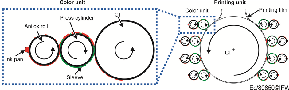
Figure 1. Printing and color unit of a flexographic printing machine.
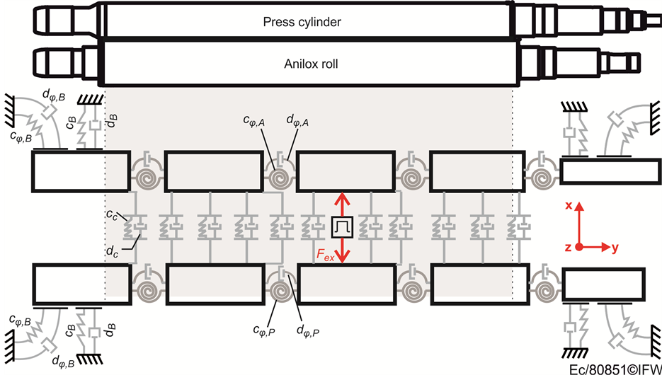
Figure 2. Multibody model of a color unit.
the rollers, the bearings have a huge influence on the dynamic behavior, which is modeled by translational springs (cB) and dampers (dB) between the end of each roller and the fixed support. Furthermore, tilting between rollers and bearings has been considered by additional torsional springs (cφ,B) and dampers (dφ,B). The contact area between anilox roll and press cylinder has been modeled by nonlinear springs (cc) and dampers (dc), which is necessary because the contact stiffness depends on the distance between the two rollers and changes in case of vibrations.
2.2. Parametrization of the Model
The parametrization of all spring and damper elements bases upon a number of dynamical measurements, which is described in the following. To carry out the measurements the modal analysis system LMS including Test. Lab 11a-Software, an impulse hammer with the integrated force sensor PCB 86C03, and a number of triaxiale acceleration sensors PCB 356A16 is used. The parametrization has been done in three steps. The first step is the parametrization of the rotational springs (cφ,P and cφ,A) and dampers (dφ,P and dφ,A) of the rollers. Therefore, both rollers have been hung up using very soft springs and acceleration sensors are placed on the surface (Figure 3(a)).
Rigid-body vibrations resulting from the soft springs are neglected, because the eigenfrequency is expected to be in a range that is not detectable by the acceleration sensors. The roller is excited in its center by a force impulse using the impulse hammer. Since the force impulse as well as the acceleration response is measured at the same time, the frequency response functions (FRFs) from the excitation point to each measurement point can be calculated.
Additionally to the measurement setup, the DMBS model is developed (Figure 3(b)). For each position of the measurement points a virtual triaxiale acceleration sensor is placed within the model. The model is excited in its center with the identical force impulse and direction as during the measurement and the resulting FRFs are calculated. Using genetic algorithm [19] the rotational stiffness and damping parameters (cφ,P and dφ,P) are determined. Therefore, the parameters were varied systematically and the simulated and measured FRFs have been compared. The fitness function of the optimization algorithm is the error between measured and simulated FRF related to the measurement point in the center of the roll (drive point FRF). The FRFs of the other measurement points are used to verify the optimization result. The mass values (mP1-mP5) and the inertia values of the inner rigid bodies (IP2 and IP3) have been taken from the CAD model. The inertia values of the outer rigid bodies (IP1

Figure 3. Measurement setup and multibody model of the press cylinder.
and IP4) have been changed through the optimization by about 15%. With the DMBS model the FRFs as well as the first and second bending eigenmodes can be simulated.
2.3. Simulation Results
Figure 4 shows the results of the press cylinder. Figure 4(a) shows that the simulated and measured drive point FRF fit very well in the area of the eigenfrequencies. The antiresonances however are not simulated with the presented model. This is due to the low resolution by using only four bodies. However, the absolute error in the area of the antiresonances is very small and thus negligible (It only seems high because the figure is in logarithmic representation). The important parts of the FRFs are the eigenfrequencies, which matches very well.
To verify the model with the other measurement points, Figure 4(b) depicts the first and second bending eigenmodes. The blue bars show the measured vibration amplitude related to the first (173 Hz) and second (433 Hz) eigenfrequency. The red line shows the simulated eigenmodes. Clearly visible are the inharmonious transitions between the rigid bodies, which could be smoothed by using a higher number of rigid bodies. Nevertheless, the comparison of the simulated and measured eigenmodes shows that the presented approach is well suited to simulate the vibration behavior. According to the press cylinder the anilox roll has been simulated and parametrized. The results, presented in Figure 5 show a high correlation between measurement and simulation as well.
Figure 4 and Figure 5 refer to the horizontal direction (x-direction). The vertical direction (z-direction) shows very similar results since the rollers are rotationally symmetric bodies.
The second step is the parametrization of the bearings. Therefore, the model is extended by translational springs and dampers (cB and dB) as well as rotational springs and dampers (cφB and dφB) at the end of the roller, shown in Figure 6.
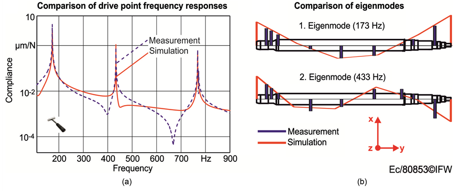
Figure 4. Simulated and measured FRF and eigenmodes of the press cylinder.
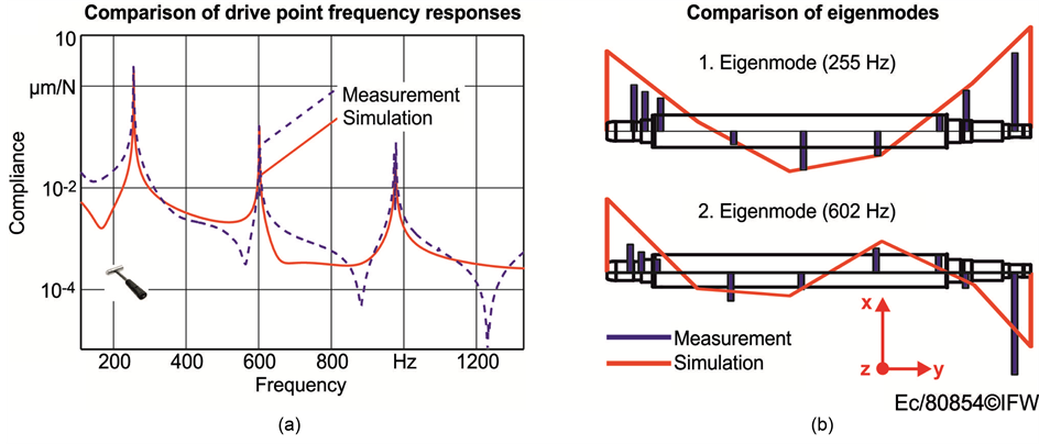
Figure 5. Simulated and measured FRF and eigenmodes of the anilox roll.
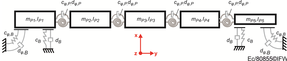
Figure 6. Multibody model of the press cylinder installed in the printing machine.
Additionally to the simulation model, the actual roller is installed within the printing machine. According to step one, the acceleration sensors are placed on the surface of the roller while the roller is excited in its center using the impulse hammer. The stiffness and damping values of the roller (cφP and dφP) as well as all mass and inertia values are adopted from step one. The values of the bearing (cφB, dφB, cB, and dB) are determined by the genetic optimization algorithm according to step one. Figure 7 shows the results for the press cylinder. The results of the anilox roll are comparable.
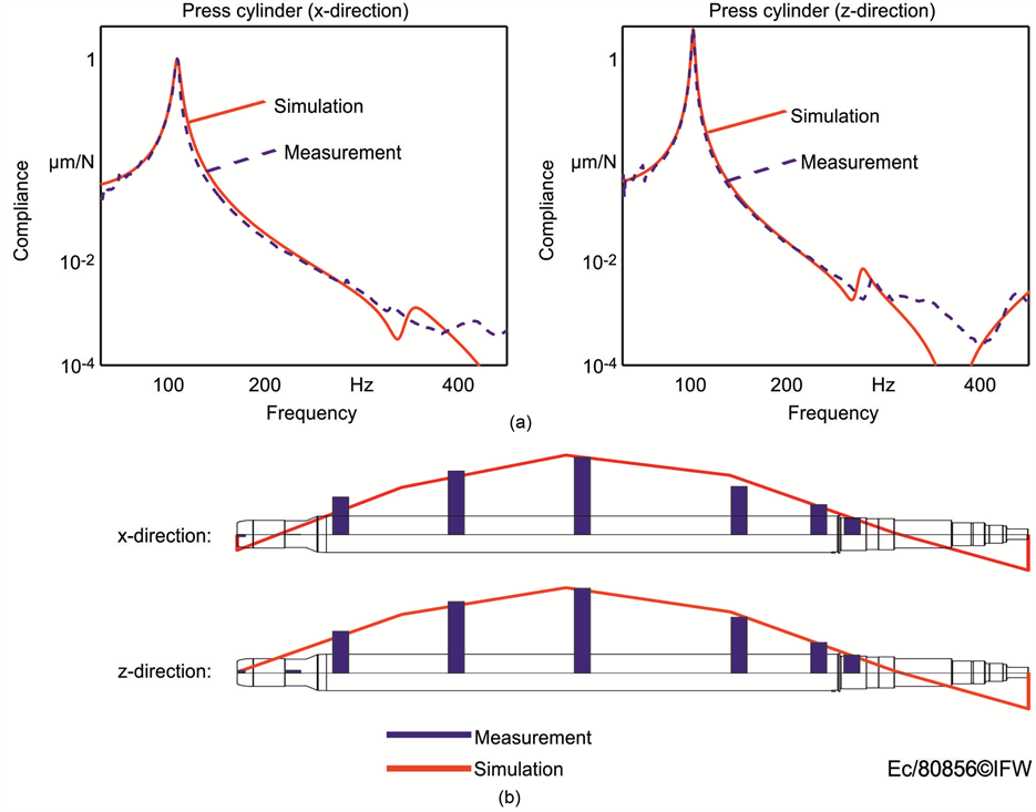
Figure 7. Simulated and measured FRF and eigenmodes of the installed press cylinder.
Since the bearing in the actual machine is not rotationally symmetric, the x-, and z-directions are investigated separately. Figure 7(a) shows the simulated and measured drive point FRF in two directions. Figure 7(b) depicts the simulated and measured eigenmodes. Simulation and measurement results match very well.
The third step is the parametrization of the rollers in contact. Therefore, the rollers installed in the actual machine are driven in contact with an overlap of 50 µm, which is a typical situation during the print process. The simulation is extended by nonlinear springs (cc) and dampers (dc) between the rollers. The stiffness and damping values are described by a third order nonlinear function.
 , (1)
, (1)
while the spring force F depends on the distance between the two rollers ∆x. The three unknown parameters a1, a2, and a3 are determined using the genetic algorithm. Therefore, each roller is excited in its center according to step one and step two. The result of this parameter study is that the parameters a2 and a3 are nearly zero and only the parameter a1 is changed by the optimization algorithm. Thus, it is enough to consider the contact stiffness as linear springs. The spring constant cc is then equal to a1. A further result is that an optimal spring constant cannot be found with the chosen boundary conditions, because the contact of the rollers also influences the stiffness of the bearings, which is explained in Figure 8. Figure 8(a) shows the drive point FRFs of the press cylinder and the anilox roll with and without contact.
The eigenfrequency of the press cylinder is 103 Hz, while the eigenfrequency of the anilox roll is 133 Hz. The difference between these values can be explained with the solid construction of the anilox roll. After moving both rollers into contact with an overlapping of 50 µm they can be considered as one single body with only one eigenfrequency, as explained in Figure 8(b). This eigenfrequency is 138 Hz. This is remarkable, because if the other stiffness values of the machine remain constant, the eigenfrequency of the rollers in contact is expected to be between the eigenfrequencies of the press cylinder (103 Hz) and anilox roll (133 Hz) without contact. Since the new eigenfrequency is higher than both values, another value of the machine must have changed due to the contact situation. It is assumed, that the bearing stiffness (cB) is increased after driving the rollers in contact. Without contact there is a bearing clearance. Due to the contact situation with an overlapping there is a force flux through the bearings which preloads the bearings and that way increases the stiffness. To consider this effect in the DMBS, the bearing stiffness of the simulation model has been increased by 50%. That way the simulation model and measurement match well, as shown in Figure 9.
3. Conclusion
In this paper, a new approach on flexible multibody simulation is presented. This approach is based on a discrete multibody modeling. The compliance of one body is modeled by dividing the body into a plurality of rigid bodies,
 (a) (b)
Figure 8. Drive point FRF with and without contact.

Figure 9. Frequency response with additional contact damping.
connected to each other by compliant elements like springs. That way, deformations under load can be simulated with less computation power required than using an FEM model. The parametrization of the springs is performed by comparing the model with an experimental modal analysis. With the application in this paper (a color unit of a flexographic printing machine), it has been proven that this method allows simulating relevant bending mode shapes and contact conditions very well. The benefits are very low computing power compared to other methods of flexible multibody modeling. A further advantage is that non-linear effects (e.g. bearing clearance, loss of contact) can be implemented easily and that the contact points can be changed during the simulation. This makes it possible to simulate e.g. linear guides. Because of the little computing time, it is also possible to implement such models in a machine control system and to support the manufacturing process in real time. Thus, non-measurable values like process forces, for instance, can be predicted by the simulation model and used for the control system.
Acknowledgements
The research studies, presented in this paper, have been part of the cooperation project AktiWa. The authors would like to thank the Federal Ministry of Economic Affairs (BMWi) for funding this project.
Cite this paper
MartinEckl,ThomasLepper,BerendDenkena, (2016) Development of a Flexible Multibody Model to Simulate Nonlinear Effects in Printing Process. Modern Mechanical Engineering,06,10-19. doi: 10.4236/mme.2016.61002
References
- 1. Cook, R.D., Malkus, D.S., Plesha, M.E. and Witt, R.J. (2002) Concepts and Applications of Finite Element Analysis. Wiley, New York.
- 2. Brenner, S.C. and Scott, R. (2008) The Mathematical Theory of Finite Element Methods. Springer, New York.
http://dx.doi.org/10.1007/978-0-387-75934-0 - 3. Dhatt, G., Touzot, G. and Lefrançois, E. (2012) Finite Element Method. Wiley, London.
http://dx.doi.org/10.1002/9781118569764 - 4. Schwerin, R.V. (1999) Multibody System Simulation: Numerical Methods, Algorithms, and Software. Springer, Berlin, Heidelberg, New York.
http://dx.doi.org/10.1007/978-3-642-58515-9 - 5. Coutinho, M.G. (2001) Dynamic Simulations of Multibody Systems. Springer, New York.
http://dx.doi.org/10.1007/978-1-4757-3476-8 - 6. Altintas, Y., Brecher, C., Weck, M. and Witt, S. (2005) Virtual Machine Tool. CIRP Annals—Manufacturing Technology, 54, 115-138.
http://dx.doi.org/10.1016/S0007-8506(07)60022-5 - 7. Litwinski, K.M., Peters, R., Overmeyer, L. and Denkena, B. (2011) Real Time Simulation Approach for the Machine Tool Design and Error Compensation. MM Science Journal—International Conference on Machine Tools, Automation, Technology and Robotics, 9, 1-7.
- 8. Craig Jr., R.R. and Bampton, M.C.C. (1968) Coupling of Substructures for Dynamic Analysis. AIAA Journal, 6, 1313-1319.
http://dx.doi.org/10.2514/3.4741 - 9. Queins, M. (2005) Simulation des Dynamischen Verhaltens von Werkzeugmaschinen mit Hilfe Flexibler Mehrkör-permodelle. Dr.-Ing. Dissertation, RWTH, Aachen
- 10. Neithard, W. (2004) Methodik zur Simulation und Optimierung von Werkzeugmaschinen in der Konzept-und Entwurf-sphase auf Basis der Mehrkörpersimulation. Dr.-Ing. Dissertation, TH Karlsruhe.
- 11. Brecher, C. (2012) Integrative Production Technology for High-Wage Countries. Springer-Verlag, Berlin.
http://dx.doi.org/10.1007/978-3-642-21067-9 - 12. Hoffmann, F. (2008) Optimierung der Dynamischen Bahngenauigkeit von Werkzeugmaschinen mit der Mehrkörper-simulation. Dr.-Ing. Dissertation, RWTH Aachen, Werkzeugmaschinenlabor, Aachen.
- 13. Siedl, D. (2008) Simulation des Dynamischen Verhaltens von Werkzeugmaschinen Während Verfahrbewegungen. Dr.-Ing. Dissertation, TU München, München.
- 14. Zaeh, M. and Siedl, D.A. (2007) New Method for Simulation of Machining Performance by Integrating Finite Element and Multibody Simulation for Machine Tools. CIRP Annals—Manufacturing Technology, 56, 383-386.
http://dx.doi.org/10.1016/j.cirp.2007.05.089 - 15. Torrez Torres, J. (2004) Aktive Regelung eines Linearmotors mit Dominanten Mechanischen Resonanzstellen. Dr.-Ing. Dissertation, TU Braunschweig, Braunschweig.
- 16. Hackelöer, F. (2014) Erweiterung der Einsatzmöglichkeiten von Magnetführungen. Dr.-Ing. Dissertation, Leibniz Universität Hannover, Hannover.
- 17. Denkena, B., Eckl, M. and Lepper, T. (2015) Advanced Control Strategies for Active Vibration Suppression in Laser Cutting Machines. International Journal of Automation Technology, 9, 425-435.
- 18. Denkena, B., Litwinski, K.M. and Eckl, M. (2015) Modeling and Compensation of the Interactions between Geometrical Errors and Drive Currents in Directly Driven Gantry Machine Tools. Production Engineering, 9, 257-267.
http://dx.doi.org/10.1007/s11740-015-0600-4 - 19. Dadios, E.P., Fernandez, P.S. and Williams, D.J. (2006) Genetic Algorithm on Line Controller for the Flexible Inverted Pendulum Problem. Journal of Advanced Computational Intelligence and Intelligent Informatics, 10.