Modern Mechanical Engineering
Vol.3 No.4(2013), Article ID:39033,5 pages DOI:10.4236/mme.2013.34020
Mechanical Behavior of Glass Fiber Reinforced Polymer Pultruded Composite Gratings
1Horizon Offshore, Inc., Houston, USA
2Department of Mechanical Engineering, Lamar University, Beaumont, USA
Email: malur.srinivasan@lamar.edu
Copyright © 2013 Rahul Mangire, Malur N. Srinivasan. This is an open access article distributed under the Creative Commons Attribution License, which permits unrestricted use, distribution, and reproduction in any medium, provided the original work is properly cited.
Received August 5, 2013; revised September 16, 2013; accepted October 2, 2013
Keywords: Mechanical Behavior; GFRP Composite; Pultrusion; Grating; FEM; Deflection
ABSTRACT
Well-designed and manufactured glass fiber reinforced polymer composite structures have several advantages over steel and conventional concrete structures such as high strength-to-weight ratio, good stiffness, good corrosion resistance and good damping capacity. In view of their higher cost however, their use is restricted to structures with smaller dimensions such as pedestrian walkways particularly where aggressive environmental conditions are encountered such as in chemical and water-treatment plants. The keys to success of these structures lie in the proper choice of the constituent materials, manufacturing method and knowledge of the behavior of the structure under the conditions encountered. Knowledge of the mechanical behavior is particularly important in this context. An investigation was therefore conducted by the authors, in partial fulfillment for the award of master of engineering science degree of Lamar University to the first author under the supervision of the second author [1], to study the response to loading of a glass fiber reinforced polyester composite structure made by the pultrusion process by a reputed manufacturer. The structure chosen for this study was a grating, the details of which are shown in the paper. This type of structure is particularly useful for walkways. The experimental part of the investigation consisted of subjecting the grating to three-point bend test under different loading conditions. The load-deflection curve for each case was obtained and interpreted. One grating was loaded up to failure and the fractured zone was examined using a scanning electron microscope to interpret the microscopic failure features. Simulation of the experimental work was carried out using an industry-standard FEM software to compare the deflection values. The results are presented and discussed in this paper.
1. Introduction
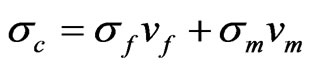
A composite material is a materials system composed of a mixture or combination of two or more micro or macroconstitutents that differ in form and chemical composition and, which are essentially insoluble in each other [2]. Its engineering importance is that the engineering properties of the composite can be tailored to specific values by suitable combination of the individual constituents. Fiber-reinforced polymer composites, for example, combine the high strength of the fibers with the engineering advantages of polymers in bulk such as light weight, ease of fabrication, relatively low cost and others. The composite of the brittle polymer and the brittle fiber can be toughened against fracture by mechanisms involving separation of the fiber-polymer interface and fiber pullout [3]. In the present paper, the constituents involved are E-glass fiber and polyester resin polymer. The tensile strength of a fiber composite loaded along the fiber can be calculated using the formula:
 (1)
(1)
where,  is the tensile strength, v is the volume fraction and the subscripts c, f and m stand for the composite, fiber and the matrix, respectively. E-glass has a tensile strength of about 1700 MPa as opposed to the typical average tensile strength of 50 MPa for polyester. If it is assumed that the volume fraction of the fiber is about 60% of the composite volume and if it is assumed that the fibers are aligned longitudinally, isostrain condition is achieved and the tensile strength of the composite would be 1240 MPa. Pultrusion process can ensure that the fibers are aligned along the direction of the pull and therefore obtaining the calculated value in a pultruded component would not be difficult. It is to be realized, however, that this figure applies to axial loading along the fiber. Under bend-load conditions, encountered in a beam, the flexural stress at failure will be much lower (less tan 600 MPa in the grating used in the present work).
2. Experimental
In Figure 1 are shown views and dimensions of the gratings used in the present investigation. Each I-section composite beam was pulled through die cavities in a pultruder, adopting standard and well-established procedures, as the manufacturer has extensive experience in this area. The pultruded beams were longitudinally aligned and transversely spaced according to established dimensions using approximately cylindrical bars, in order to produce a grating. The gratings were then brought to the authors’ laboratory and subjected to three-point bend test using a standard compression-tension testing machine. In Figure 2 is shown a schematic diagram of the loading set up. Instead of using a knife edge for loading, a cylindrical bar was placed along the grating flange to minimize damage while loading.
In the initial stages, a strain gage was used as the main device for measuring deflection along with a dial gage as a backup. The two devices showed identical values and therefore it was decided to discontinue the use of strain gage and use the dial gage readings for measuring the deflection, as the use of the latter was more convenient.
One of the primary objectives of this study was to determine the mechanical behavior of the grating in frequent pedestrian traffic. For this purpose a grating was initially loaded to full failure under monotonic loading and the maximum load was noted. As seen in Figure 3, this load is 11,000 lb (48,400 N). The load-deflection curve shows linear behavior up to 4000 lb (17,600 N) and this was assumed to be the maximum safe load for pedestrian traffic. Another grating was then loaded up to 4000 lb (17,600 N), unloaded and loaded again to 4000 lb (17,600 N) and unloaded again. This procedure was repeated 5 times and load-deflection in each case was noted. The results are shown in Figure 4. It is seen that the load-deflection curves are nearly the same in each case, indicating that a maximum load of 4000 lb (17,600 N) may be considered to be safe for frequent pedestrian traffic. The next object was to evaluate the fracture zone features of the grating that failed at 11,000 lb (48,400 N). For this purpose, carefully sawed-off pieces from the fracture zone were examined in a scanning electron microscope (SEM). A typical SEM picture is shown in Figure 5.
The mode of fracture is predominantly neighboring fiber fracture, indicating that the probable reason was the high volume fraction of the fiber (~60%).
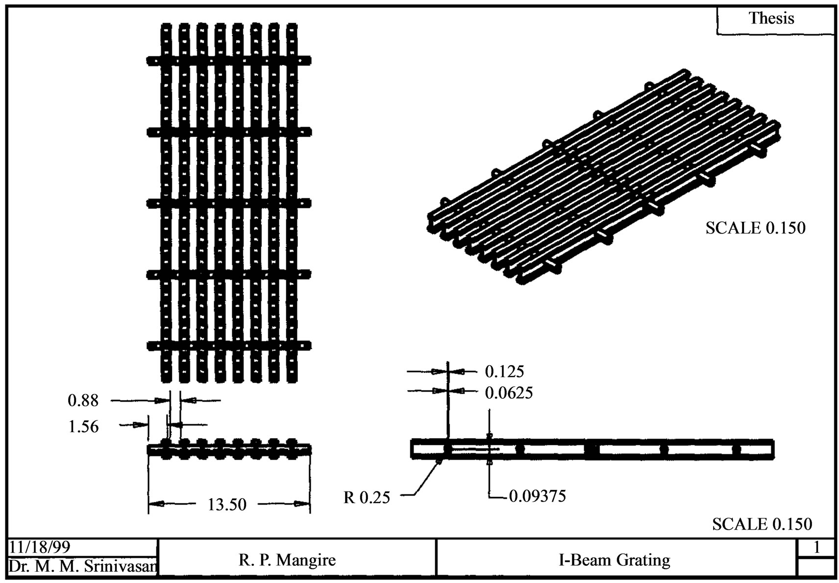
Figure 1. Views and dimensions of grating.
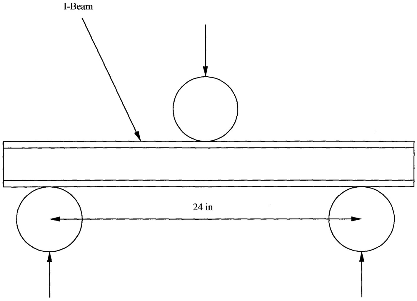
Figure 2. Schematic diagram of loading setup.
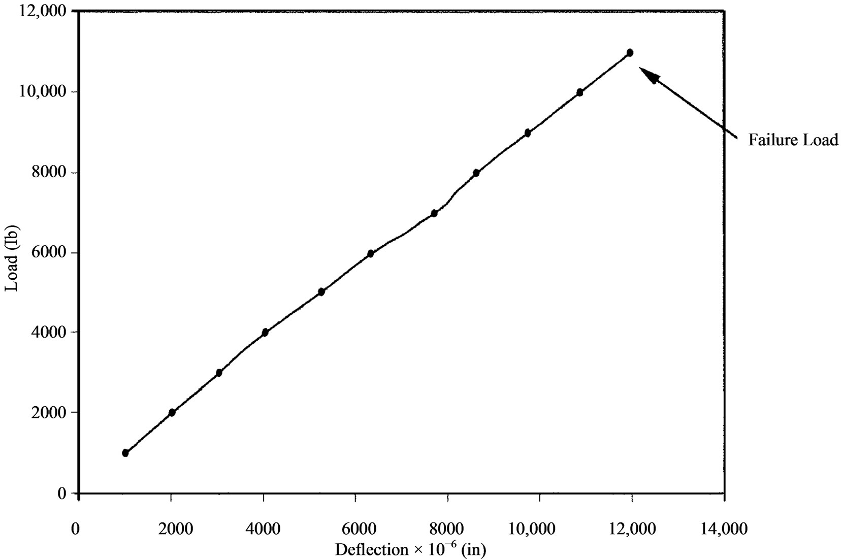
Figure 3. Load-deflection curve for grating (1 inch = 25.4 mm, 1 lb = 4.4 N).
3. FEM Simulation
Individual grating beams were modeled using an industry-standard software (Pro/MECHANICA) and deflections were determined at different loads similar to those used in experimental work. Figure 6 shows the comparison of the FEM results with the experimental.
It is seen from the figure above that though the trend in the deflection is similar in both cases, the FEM values are somewhat lower than the experimental values. The interface between the spacer bars and the I beams was made strong with adhesives in the actual gratings, but this could not be modeled in FEM. The strong adhesive imparts additional rigidity to the grating making the ac-
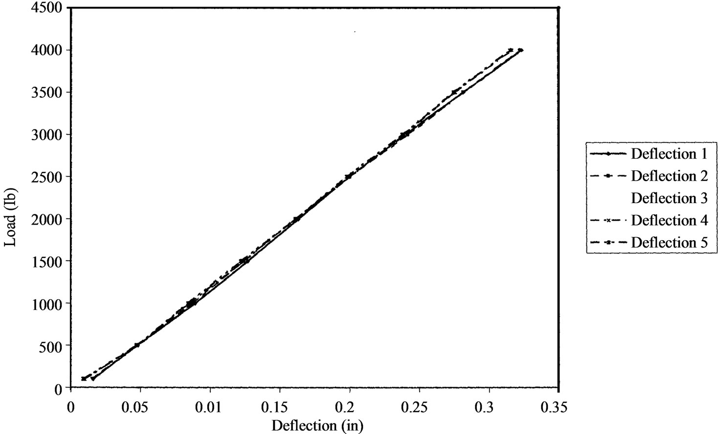
Figure 4. Load-deflection curves for repeated loading and unloading of grating (1 inch = 25.4 mm, 1 lb = 4.4 N).
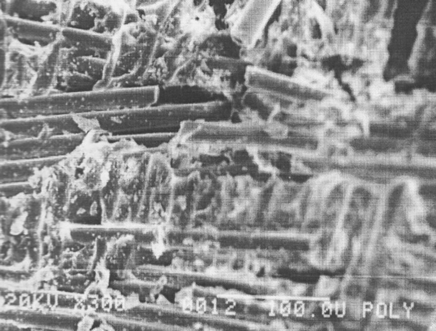
Figure 5. SEM picture showing neighboring fibers fracture (×300).
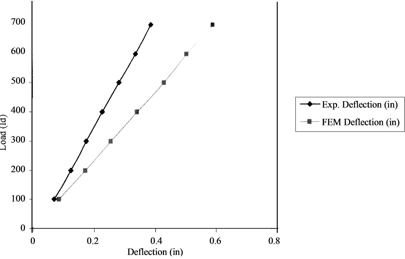
Figure 6. Comparison of FEM and Experimental Deflections.
tual (experimental) deflections lower for a given load.
4. Concluding Remarks
The authors have attempted to study the mechanical behavior of pultruded E glass-reinforced polyester (thermosetting type) composite grating manufactured by a well-known producer having an experience of over fifty years in the field. The authors acknowledge the awesome achievements of the manufacturers [4] and hope that the results of the present work will be useful additions to the knowledge-base of pedestrian gratings generated by the manufacturers.
The main conclusions of the present work are that the gratings are reasonably safe for frequent pedestrian traffic provided the load is restricted to 4000 lb (17,600 N). If higher loads are to be tolerated, detailed studies on fatigue behavior at higher loads will have to be made. A high volume fraction (about 60 percent) of fiber is good for increasing the strength of the composite but may have adverse effect on fatigue behavior and fracture when unintended flaws are present. Pultrusion is an excellent process for producing well-aligned fiber gratings, evident in the microstructure observed.
5. Acknowledgements
The authors are grateful to TxDOT for financial support and to Fibergrate, Inc. (formerly Composite Structures International, Inc.) for providing the gratings for this research.
REFERENCES
- R. Mangire, “Micro-macro Mechanical Behavior of Fiber-Reinforced Pultruded Composite Gratings,” M.E.S. Thesis, Lamar University, Beaumont, 1999.
- W. F. Smith, “Principles of Materials Science and Engineering,” 3rd Edition, McGraw-Hill Book Company, New York, 1996, p. 768.
- J. P. Schaffer, A. Saxena, S. Antolovich, T. H. Sanders, S. B. Warner, “The Science and Design of Engineering Materials,” McGraw-Hill Book Company, New York, 1999, p. 595.
- Fibergrate, Inc., 2013. http://www.fibergrate.com.