Modern Mechanical Engineering
Vol.3 No.1(2013), Article ID:28250,6 pages DOI:10.4236/mme.2013.31002
An Effective Approach for Optimal PZT Vibration Absorber Placement on Composite Structures
Department of Mechanical Engineering, The University of Texas at Tyler, Tyler, USA
Email: yjlin@uttyler.edu
Received November 19, 2012; revised December 23, 2012; accepted January 4, 2013
Keywords: Piezoelectric; Modal Analysis; Vibration Absorber; Damping; Shunt Circuit
ABSTRACT
In this paper, an attempt is made to determine the electric potential that would be generated in the piezoelectric vibration absorber using finite element piezoelectric analysis to determine optimal locations for damping of the first mode. Optimal placement of piezoelectric vibration absorber for passive vibration control application of a cantilever composite plate is investigated. Finite element piezoelectric modal analysis is performed. Models based on placing piezoelectric vibration absorbers at five different locations on the surface of the plate and incorporating piezoelectric properties are built. Modal analysis is used to find the electric potential developed in the piezoelectric vibration absorber. The location that yields the highest amount of electric potential would naturally be the best location for the vibration absorber. First bending mode of the cantilever composite plate is aimed for damping. Results of the analysis are verified with an experimental testing of the composite plate with piezoelectric vibration absorber firmly attached to the plate on the most effective location. A good agreement is found between the analytical and experimental results. Further, a resistive shunt circuit is designed for the passive damping of the first mode and attached to the vibration absorber in which the electric potential developed would be dissipated as heat to obtain passive vibration compensation. The experiment also demonstrates that a damping of 6 percent is obtained in the first mode of vibration and a great amount of damping is achieved in the second and third modes as well.
1. Introduction
A piezoelectric vibration absorber is a patch of piezoelectric actuator placed on the surface of the plate to be damped, which is shunted with resistive, inductive, or both types of circuits designed to damp one or more modes. The mechanism of damping is based on the energy dissipation in the shunt circuit. The key factor in effective damping is the voltage developed in the piezoelectric vibration absorber as a result of energy conversion in the piezoelectric material. The higher the voltage, more is the damping amount of vibration control. Conventionally, the passive vibration absorbers are placed at the locations where the strain energy in the structure is at the highest value. These locations are determined by conducting stress analysis of the structure. However, several optimization methods have been proposed and many more are under study with the use of piezoelectric actuators and sensors in smart structures. Optimization of the locations of the piezoelectric sensors and actuators placement using generic algorithms has been proposed by Han and Lee [1]. Jia and Rogers [2] considered using finite elements with eigenvectors consisting not only of nodal displacements, but also of electric potentials to minimize the control effort for damping the vibrations in a truss structure. Pin-force model was used by Renato et al. [3] to find the optimal placement of PZT actuators for the control of beam dynamics. Simultaneous optimization of piezoelectric actuator placement and feedback gain for vibration control was studied by Yong et al. [4]. However, the above methods were not aimed at finding the electric potential that would be generated in the piezoelectric material, which is the key factor in vibration attenuation. Though, the study of strain energy distribution in the plate would give a fairly accurate idea of the best location for the passive damping element, the modal piezoelectric analysis gives us a pretty straightforward output of the electric potential that would be obtained, which is our final requirement. It is natural that the more the electric potential in the transducer, the more the energy extraction and hence, the more is the damping. This kind of analysis is essential to effectively utilize the piezoelectric transducers. Placing the transducers at the locations, which would not yield significant electric potential will lead to poor damping [5-8]. In this paper, an attempt is made to determine the electric potential that would be generated in the piezoelectric vibration absorber using finite element piezoelectric analysis to be based on for determining the optimal location for the damping of the first mode of vibrations.
2. Finite Element Analysis
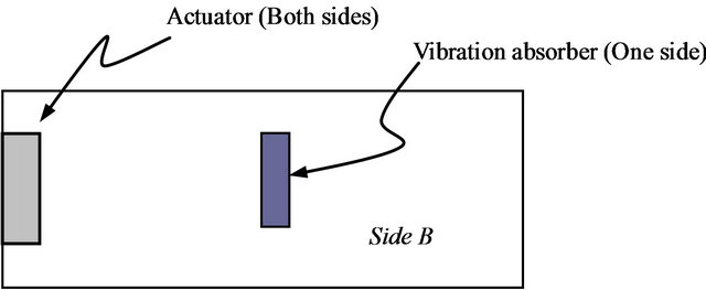
In order to understand the vibration characteristics of the cantilever plate, modal analyses are performed with and without the piezoelectric vibration absorbers. The cantilever composite plate that was considered has a pair of PZT actuators near and parallel to the fixed edge on both sides and a sensor on one side.
Initially, a finite element model of the plate with these actuators and sensor was built and modal analysis was performed to obtain the natural frequencies, mode shapes and strain energy distributions for different modes. The mass and stiffness of the piezoelectric materials were also considered. However, the piezoelectric effect was not taken into account, as it is not required.
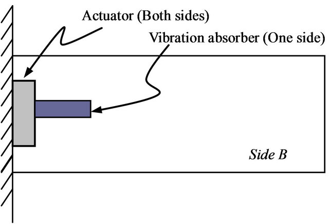
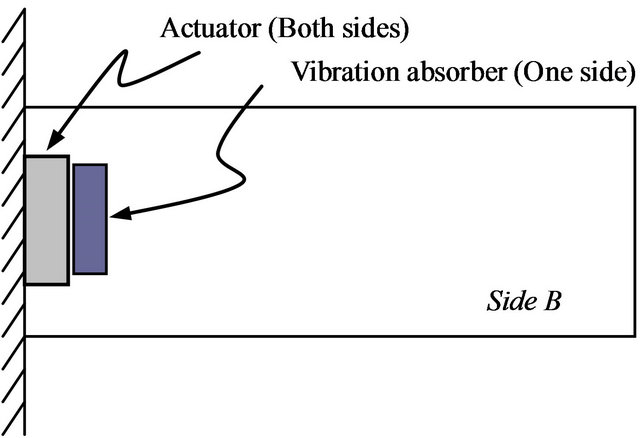
Then, five locations are chosen randomly for the placement of the passive piezoelectric vibration absorber (Figure 1). Passive damping piezoelectric transducer locations are considered on the surface of the plate on which there is no sensor. This surface is chosen, as it gives more options and the transducer locations can be chosen at a place closer to the actuator, where the strain energy concentration is high in the first mode. The properties of the piezoelectric materials are obtained from the manufacturer of the piezoelectric actuators from where the actuators, sensors and vibration absorber are acquired. In addition to the mass and stiffness of the vibration absorber, the piezoelectric properties of the vibration absorber are also defined, to perform the piezoelectric modal analysis.
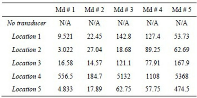
A finite element model was built for each location considered and modal analysis was carried out to determine the natural frequencies, mode shapes, strain energy distributions and the electric potential developed in the vibration absorber. The first five natural frequencies of the plate with and without the passive vibration transducers are given in Table 1. The electric potentials obtained in the piezoelectric transducers are given in Table 2. Highest amount of electric potential is obtained at location # 4.
3. Shunt Circuit
Once the location for the piezoelectric transducer is finalized, the shunt circuit in which the energy would be dissipated is to be designed. The electrical energy produced in the piezoelectric vibration absorber is forced to flow as an electric current in the external circuit and be dissipated by joule heating through the shunt circuit. The elements of the shunt circuit can be of different kinds. It may consist of resistance only [9], resistance and inductance
(a) Location # 1
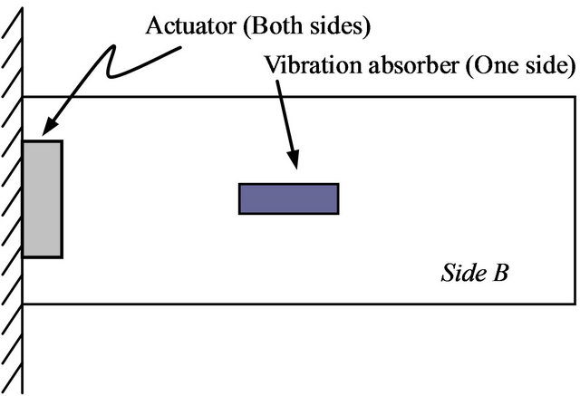
(b) Location # 2
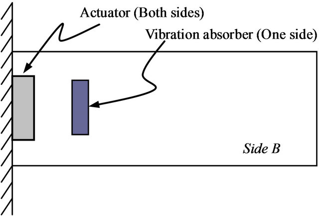
(c) Location # 3
(d) Location # 4
(e) Location # 5
Figure 1. Passive vibration absorber locations.
Table 1. Natural frequencies of the composite plate (Hz).
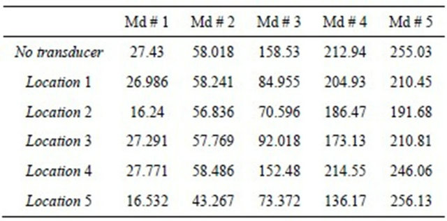
Table 2. Electric potential in piezoelectric transducer.
in series [9] or resistance and inductance in parallel [10]. Due to the relative simplicity in design and ease of practical implementation, resistance only type of shunt circuit is considered in this work. The shunt resistor can be thought of as changing the material properties of the piezoelectric vibration absorber. For a given resistance the stiffness of the piezoelectric material changes from its short circuit value at low frequencies to its open circuit value at high frequencies. The frequency of this transition is determined by the shunting resistance. The material also exhibits a maximum loss factor at this transition point. The value of this maximum loss factor, given by Hagood and Flotov [5], can be found to be
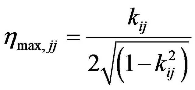 (1)
(1)
At a non-dimensional frequency of
 (2)
(2)
where  is the electromechanical coupling coefficient of the piezoelectric,
  is the shunt resistance,
  is the piezoelectric capacitance across the electrodes when the piezoelectric vibration absorber is bonded to the structure and w is the frequency. The subscripts i and j represent the direction of electric current and the direction of strain, respectively. Thus by an appropriate choice of resistor, the peak of the loss factor curve can be manipulated and moved to the desired frequency.
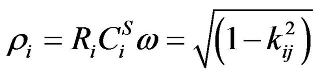
The above equations are good when strain is in onedirection only. But, in the case of plates, we have twodimensional or planar strains. To incorporate this change we have to use a different set of equations for calculating the shunt resistance. Also, Equation (2) does not include any energy losses that may occur during the transfer of energy from one form to another. The more accurate method would be to use the generalized electromechanical coupling coefficient (K), which is defined as the square root of the ratio of electrical energy and mechanical energy. That is,
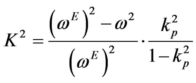 (3)
(3)
where w is the natural frequency of the structure without piezoelectric transducer and wE is the natural frequency of the structure with piezoelectric vibration absorber attached to it but shortened. kp is the planar electromechanical coupling coefficient of the piezoelectric given by the manufacturer. Equation (3) thus, incorporates the external factors in the form of change in frequencies and also the planar electromechanical coupling coefficient is used which is more appropriate for plates. The expression for shunt resistance, given in Wu and Bicos’s work [10], is written as
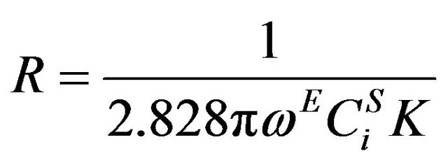 (4)
(4)
where,  is the piezoelectric capacitance across the electrodes when the piezoelectric vibration absorber is bonded to the structure, which is given as
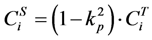 (5)
(5)
where  is the specified capacitance of the piezoelectric vibration absorber given by the manufacturer.
The manufacturer specified values of the constants are as follows,
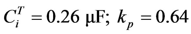 .
.
The first five natural frequencies of the laminate composite plate, with and without piezoelectric vibration absorber are obtained and given in Table 1. From the values of frequencies and the manufacturer specified constants, shunt resistance value is calculated from Equation (4), that is
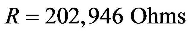 .
.
4. Experimental Testing and Findings
The experimental setup for the vibration testing of the prototype plate, with actuators, sensors and piezoelectric passive piezoelectric vibration absorber attached to it at location # 4 (Figure 1(d)) is shown in Figure 2. The laminate composite plate is securely fastened as a cantilever to a vertical support designed for the purpose. The vertical support is rigidly held to a table with C-clamps. The actuators located at the fixed edge of the plate are connected to an arbitrary waveform generator through an amplifier. Actuators placed near the fixed end of the plate are connected to an arbitrary waveform generator through an amplifier. Arbitrary waveform generator generates the necessary signals to actuate the structure for testing purposes. Amplifier magnifies the input signal to the actuator, so that desired amount of deflections are produced in the plate. Sensor is connected to dSPACE data acquisition system and real time Matlab Simulink interface. The response of the structure to various signals can be observed and the data can be stored for further analysis with this kind of arrangement. Sensor can be connected to an oscilloscope to visually examine the responses of the structure. The experimental procedure consists of two steps. First one is to verify the FE modal analysis results for the natural frequencies of the structure. This is achieved by exciting the structure through sweeping a sine wave over the actuators. The frequency is increased slowly and
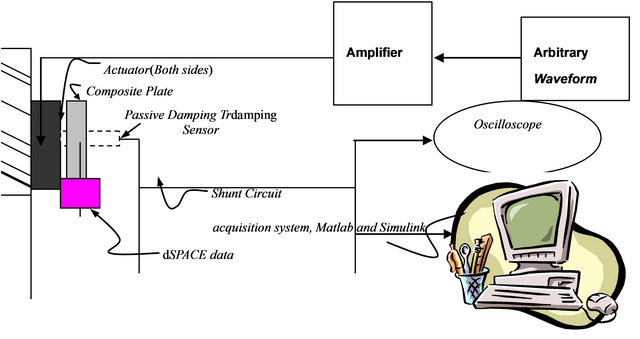
Figure 2. Experimental test rig.
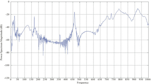
Figure 3. Responses of the plate to a sweep sine input signal (up to 1000 Hz, 1.0 v).
gradually from 0 Hz to 500 Hz. The frequencies can be adjusted to three decimals to obtain precise values as shown in Figure 3. When the frequency matches the natural frequency of the structure, due to resonant condition the plate vibrates heavily. The vibrations of the plate can be observed by connecting the sensor to an oscilloscope. Due to the use of only one sensor, all the modes could not be detected simultaneously. Only the first few modes could be picked up by the sensor, because of its location set on the plate.
Alternately, the modal response of the structure can be obtained by giving a sine wave input signal. The output signal from the sensor was captured with the help of dSPACE. The responses of the plate to a sweep sine input signal, without the shunt circuit attached to it, is shown in Figure 3. It is obvious from the figure that the experimental results agree with the FE analysis results for most of the modes, particularly, the first and third modes, occurred approximately around 35 and 170 Hz, respectively.
The second step is to test the amount of damping obtained. This is obtained by analyzing the response of the structure to small tapping at its free end with and without the shunt circuit attached to the piezoelectric transducer. Data obtained from sensor is captured and the “psd” plot of frequencies with and without the vibration absorber is given in Figure 4. Damping of about 6 percent is obtained in the first mode and a good amount of damping is obtained in the other modes too. The overall robustness of the structure has been increased noticeably due to the inclusion of the shunt circuit.
The amount of electric potential developed in the passive vibration absorber is obtained by using it as a sensor and connecting it to the oscilloscope and by exciting the plate at different modes using the actuators. Table 3 provides a comparison of the electric potentials obtained from the analyses and experiment. The electric potentials generated in the vibration absorber exhibit the same trend as that we obtained from the analyses. The electric potential values obtained from the experiments in the vibra-
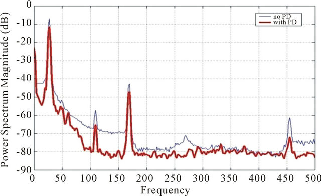
Figure 4. Comparison of vibrations with and without the shunt circuit.
Table 3. Electric potential obtained in the vibration absorber at location # 4 (mV), Figure 2(d).
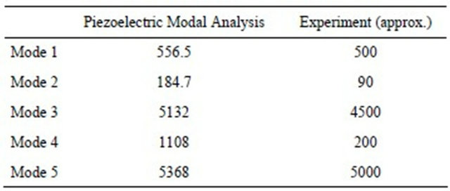
tion absorber for Modes 2 and 4 are lower due to the fact that these modes are twisting modes and they cannot be excited well with the current location of actuators. Also the location of the vibration absorber is at a place where the strain energy in the plate is very low. However, the values of the electric potentials agree fairly well for the first, third and fifth modes which are the bending modes and could be excited well with the current location of the actuators. In this case, the location of the vibration absorber also contributes to the high voltage.
5. Conclusion
From the results obtained it can be concluded that piezoelectric modal analysis serve as a very good tool in determining the location of the passive vibration absorber without much effort. This method, compared to others, is more effective which enables us to predict the electric potential that would be generated in the vibration absorber on which the amount of damping depends directly. This method can also be used in optimizing not only the location, but also the size and shape of the passive vibration absorber to obtain maximum amount of damping. This can be achieved by simply changing the dimensions and shape of the piezoelectric vibration absorber in the finite element model on an iterative basis to find the configuration that gives maximum electric potential. Piezoelectric modal analysis can also be used in optimization of the location of the actuators and sensors for various applications to minimize the actuation effort and to maximize the sensing capability, respectively. In addition, considering the mass and stiffness of the piezoelectric material, analysis can be brought much closer to reality and hence the results predicted would be highly accurate.
6. Acknowledgements
This project was supported in part by OAI CCRP program. The authors gratefully acknowledged the agency and research funding awarded.
REFERENCES
- J. H. Han and I. Lee, “Optimal Placement of Piezoelectric Sensors and Actuators for Vibration Control of a Composite Plate Using Genetic Algorithms,” Smart Materials and Structures, Vol. 8, No. 2, 1999, pp. 257-267. doi:10.1088/0964-1726/8/2/012
- J. Jia and C. A. Rogers, “Optimal Placement of Piezoelectric Actuators in Adaptive Truss Structures,” Journal of Sound and Vibration, Vol. 171, No. 1, 1994, pp. 67-85. doi:10.1006/jsvi.1994.1104
- B. Renato, M. Alessandro, F. Enrico and G. Paolo, “Optimal Placement of PZT Actuators for the Control of Bema Dynamics,” Smart Materials and Structures, Vol. 9, No. 1, 2010, pp. 110-120.
- L. Yong, O. Jungiro and M. Kenji, “Simultaneous Optimization of Piezoelectric Actuator Placement and Feedback for Vibration Suppression,” Acta Astronautica, Vol. 50, No. 6, 2012, pp. 335-341.
- R. E. Holman, S. Spencer, E. Austin and C. Johnson, “Passive Damping Technology Demonstration,” SPIE, Vol. 2445, No. 1, 1995, pp. 136-148.
- J. Hollkamp and R. W. Gordon, “An Experimental Comparison of Piezoelectric and Constrained Layer Damping,” SPIE, Vol. 3045, No. 1, 1997, pp. 51-59.
- S. Yau and Y. Wu, “Piezoelectric Shunt Vibration Damping of F-15 Panel under High Acoustic Excitation,” SPIE, Vol. 3989, No. 2, 2010, pp. 276-287.
- S. Venna, “Passive Vibration Control of a Cantilever Laminated Composite Plate with Piezoelectric Transducer and Viscoelastic Material,” M.S. Thesis, University of Akron, Akron, 2007.
- N. W. Hagood and F. Von, “A. Damping of Structural Vibrations with Piezoelectric Materials and Passive Electrical Networks,” Journal of Sound and Vibration, Vol. 146, No. 2, 2001, pp. 243-268. doi:10.1016/0022-460X(91)90762-9
- S. Wu and A. S. Bicos, “Structural Vibration Damping Experiments Using Improved Piezoelectric Shunts,” SPIE, Vol. 3045, No. 1, 1997, pp. 40-50. doi:10.1117/12.274217