Open Journal of Composite Materials
Vol.08 No.03(2018), Article ID:85887,26 pages
10.4236/ojcm.2018.83008
Laminate Tailoring of Composite Tubular Structures to Improve Crashworthiness Design at Off-Axis Loading
A. Rabiee, H. Ghasemnejad*
Centre for Structures, Assembly and Intelligent Automation, Cranfield University, Cranfield, UK

Copyright © 2018 by authors and Scientific Research Publishing Inc.
This work is licensed under the Creative Commons Attribution International License (CC BY 4.0).
http://creativecommons.org/licenses/by/4.0/


Received: May 10, 2018; Accepted: July 7, 2018; Published: July 10, 2018
ABSTRACT
This paper presents experimental and numerical investigation on the parameters effecting energy absorption capability of composite tubular structures at oblique loading to improve crashworthiness performance. Various inclined angles of 5˚, 10˚, 20˚ and 30˚ were selected for the study of off-axis loading. The results indicate that by increasing the lateral inclination angle the mean crushing force and also energy absorption capability of all tested sections decreased. From design perspective, it is necessary to investigate the parameters effecting this phenomenon. The off-axis loading effect that causes significant reduction in energy absorption was investigated and the effected parameters were improved to increase energy absorption capability. To establish this study, 10˚ off-axis loading was chosen to illustrate the obtained improvement in energy absorption capability. Five cases were studied with combinations of ply-orientation and flat trimming with 45˚ chamfer. This method was applied to the integrated 10˚ off-axis loading and the final results showed significant improvement in energy absorption capability of composite absorbers. Finite element model (FEM) was developed to simulate the crushing process of axial and off-axis composite section in LS-DYNA and the results were in good agreement with the experimental data.
Keywords:
Crashworthiness, Composites, Laminate Tailoring, Off-Axis, Oblique

1. Introduction
The ability of a structure providing protection for occupants by absorbing the applied energy through controlled failure modes in case of an impact is known as structural crashworthiness. High-energy absorption capability of a structure subjected to impact enables reduction of overall damage to the main body structure and most importantly provides greater passenger safety. In aerospace and automotive industry, the global interest is oriented towards lightweight structures for optimum energy efficiency without compromising occupant safety. The major design parameter is aligned with passenger safety; therefore, materials with high energy absorption capabilities are developed for light-weighting-safety trade-off. Composite materials such as FRPs compared to metallic structures have higher stiffness-to-weight and strength-to-weight ratio that enables an outstanding lightweight crashworthiness characteristic including excellent specific energy absorption (SEA) due to its crushing behaviour [1] [2] [3] [4] [5] .
Axial crushing behaviour is reached through four failure modes of global buckling, local buckling, fracture and progressive crushing for axial crushing of composite tubular structures and is defined as characteristic of the material absorbing energy by fragmentation and destruction. Progressive crushing however, leads to the highest specific energy absorption as structure does not fail through instabilities [6] [7] .
Different types of crashworthy components were studied in the past two decades including material systems, various geometrical shapes and various fabrication methods were developed and axially tested [8] [9] . Since during an impact event, the thin-walled structures undergo severe collapse failure and in oblique loading conditions, it could suffer from drastic energy absorption reduction. In automotive applications for instance, the bumper system is expected to endure a load with impact angle of up to a 30˚ to its longitudinal axis [10] . Therefore, maintaining high crashworthiness behaviour under different loading conditions is essential to be met whilst meeting the critical requirement of structural collapse [10] - [16] .
In practice, the above concern is mainly based on the fact that axial crushing always accompanies with high energy absorption capability through progressive crushing. However, according to previous studies on axial crushing behaviour and oblique loading [10] [12] [14] [15] , at oblique loading, the absorbers could experience an initial peak load followed by catastrophic failure which results into low energy absorption. Extensive studies have concerned with this phenomenon [17] [18] [19] .
However, only a few works were focused on crushing performance of composite structures under non-axial loading also referred to as oblique loading (off-axis loading) compared to axial loading [19] [20] [21] . Off-axis crushing is critical to study due to its importance in most applications, as impact load usually occur in an angle on composite absorber structures. Off-axis loading occurs for instance when a spinning vehicle impacts an object from a direction not along its longitudinal axis. Angled loading on the other hand occurs when a vehicle moving forward along its longitudinal axis impacts an object perpendicular to the longitudinal axis. Different fracture mechanisms are observed in off-axis crushing than axial crushing in composite structures. During oblique progressive crushing, non-symmetrical crack propagation at the intra-wall tube and between inner and outer fronds influences the dissipation of crushing energy greatly [19] .
In the study of non-axial crushing of E-glass/polyester pultruded tubes with rectangular cross-section, Czaplicki et al. [22] examined two types of non-axial loadings: off-axis loading and angled loading. They demonstrated that these two types are different in friction but similar in energy absorption tendency when the angle of inclination changes. Compared with axial crushing, the mean crushing force increases around at 10˚ non-axial angle and then continuously drops as the angle of inclination increases. Ghasemnejad et al. [19] [23] [24] experimentally investigated the axial and off-axis crashworthy behaviour of CFRP and GFRP composite box structures with inclination angles of 5˚, 10˚, 20˚, and 30˚ under quasi-static loading. The authors concluded that at 10˚ off-axis loading the mean crushing force exceeds axial loading by 12%. This conflict with another study that the author [25] concluded that as the inclination angle increased the crashworthy behaviour of composite tubes were decreased significantly. The author also noted that this might have been due to geometry difference compared with previous studies. The author experimentally investigated the axial and off-axis crushing behaviour of E-glass/epoxy composite tubes with inclination angles of 5˚, 10˚, 20˚, and 30˚ under quasi-static loading conditions.
Mamalis [26] investigated the crashworthy characteristics of composite structures by observing the brittle failure modes, such as progressive end-crushing, local tube-wall buckling and mid-length collapse, through a series of static and dynamic axial compressive tests. Song and Du [21] experimentally studied the energy absorption of five different circular GFRP tubes with different off-axial crushing angles, varying from 5˚ to 25˚ with an increment of 5˚. Greve et al. [27] conducted the impact tests and simulated the fragmentation process of braided carbon/epoxy composite tubes under axial and oblique loading conditions.
In recent studies, the crushing behaviour of composite structures subjected to axial and oblique loads have gained increasing attention [28] [29] [30] [31] . Zhou et al. [32] [33] for example investigated conventional square tubes and origami crash boxes under axial and off-axis loading and noted that origami crash box subjected to range of loading angles are potentially more desirable than conventional square tube. Sun and his co-authors [34] [35] [36] investigated the functionally-graded thin-walled structures crash characteristics under multiple loading angles using finite element analyses (FEA). Zarei [37] investigated on crashing response of simple and hybrid composite tubes with various numbers of GFRP overwrap.
Following the current state-of-the-art, it can be concluded that in the case of off-axis loading conditions, the mechanical response varies with change of geometry. However, none of the reviewed articles studied the case of introducing tailoringof lay-up sequence and the engagement of the cross-sectional area of the triggered end of the tube with the crushing plate together in one study to correct the off-axis loading and to improve energy absorption capabilities. Assessing the crashworthiness of composite tubes subjected to off-axis loading is of particular interest in the aerospace industry because, in addition to the absorbers allocated axially there are off-axis positioned absorbers that can be improved for their energy absorption capabilities. In this paper, glass/epoxy tubes were tested under quasi-static compression tests for their crushing behaviour. The off-axis loading effect that causes significant reduction in energy absorption is investigated and the effected parameters are identified and improved to increase energy absorption capability. To establish this study, 10˚ off-axis loading was chosen to illustrate the obtained improvement in energy absorption capability.Five cases were also studied with combination of ply-orientation and flat trimming 45˚ chamfer to evaluate their effect on energy absorption capabilities. This improves mean crushing force and subsequently increase specific energy absorption (SEA).
In all previous studies several FE models were introduced to achieve force-displacement curves focusing on different parameters including contact definition and crack propagation modelling. The aim of this paper is to fulfil demands for a finite element model that can be used in axial and off-axis loading conditions using multi-shell configuration in LS-DYNA.
2. Experimental Method
2.1. Material and Specimens
In this study the composite sections were fabricated from glass/epoxy (ρ = 2250 kg/m3) with a symmetric twelve-ply laminate design of [-45/45/0/90/0/90]S using hand lay-up techniques. The composite sections were 80 mm × 80 mm with the total thickness of 3 mm in size (see Figure 1). In this research, the main study is oriented around identifying the effect of off-axis loading and ways to improve crashworthiness at off-axis loading. Therefore, one of the lateral inclined angle was chosen which is at 10˚ to carry out further study. At simplified off-axis

Figure 1. Composite crush tube specimen.
loading configuration compared with axial loading, two major differences can be identified, lay-up sequence and engagement of the triggered end cross-sectional area of the specimen with the crushing plate. Therefore, the stacking sequence was adopted and the top end of the specimen was flattened to study their crashworthiness and crushing behaviour under quasi-static loading compared with axial crushing behaviour.
The integrated stacking sequence of [-55/35/-10/80/-10/80]S was adopted and used to cancel the 10˚ off axis effect. The main concentration of this research is the force/displacement curve to evaluate the energy absorption capability in each case. All parameters were kept constant in this research including geometry, strain rate, loading conditions and only the lay-up sequence and flat trimming varied depending on the case of study to obtain its effect on energy absorption capability. The main differences of 10˚ off-axis with integrated off-axis at 10˚ are the tailored lay-up sequence and the flat trimming.
2.2. Experimental Setup
A hydraulic press consists of a moving cross head which is mounted to two 500 kN screw jacks, and two large “I” beams attached to two large end blocks. The screw jacks are mounted on the bottom block and are driven by a double output, dual reduction worm gear powered with a 1492-watt AC motor. The cross head translates vertically with four precision profile rails which are mounted on the web of the vertical “I” beams.
The quasi-static testing was conducted using a hydraulic press with load cell capacity of 500 kN with crushing rate of 2 mm/second. All specimens were placed at the centre of the stroke for equal load distributions (see Figure 2). The stroke displacement for all specimens was kept the same at 50 mm. The profile of load-displacement consists of load cell and stroke displacement and was recorded automatically for each test.
3. Results and Discussion
3.1. Crushing Behaviour of Composite Sections under Axial and off-Axis Loading
In this section, the effect of lateral inclination angle is experimentally investigated. Various angles of 5˚, 10˚, 20˚ and 30˚ were selected for off-axis loading. In previous studies [19] [24] , the crushing behaviour of box composite sections were investigate based on their energy absorption capability. It was prevailing that at 10˚ the energy absorption was significantly increased, in contrast, [8] the author studied cylindrical GFRP composite section and concluded that the increase in lateral inclination angle causes a significant drop in energy absorption and this is due to the geometry differences of two studies.
The experimental morphologies (see Figure 3) of axial and off-axis angle 5˚ illustrated bundle fracture and close to brittle failure mechanism, which is a combination of lamina bending and transverse shearing modes. The results indicated that as the lateral incline angle increases the mean crush force and energy absorption decreases (see Figure 4). Axial loading compared with off-axis loading has better energy absorption capability with mean crush force of 100 kN. Off-axis angle 10˚ showed transverse shearing mode characterised by wedge-shaped laminate cross section with multiple short interlaminar fractures and axial cracks. Off-axis angles of 20˚ and 30˚ showed catastrophic failure mechanism with unsymmetrical damaged area. This change results into minimizing the energy absorption capability of the absorber.
3.2. Axial Crushing and Improvement of Off-Axis Loading
According to various positioning of composite absorbers in aircraft and automotive structures, composite specimens were tested under axial and off-axis conditions at various off-axis angles.

Figure 2. Axial and off-axis quasi-static setup.

Figure 3. Plane view of crushed axial and off-axis specimens (a) axial with brittle fracture crushing mode; (b) 5˚ with brittle fracture mode; (c)10˚ with transverse shearing mode; (d) 20˚ with catastrophic failure; (e) 30˚ with catastrophic failure.

Figure 4. Force-displacement of axial and off-axis angles of 5˚, 10˚, 20˚ and 30˚. Mean Force: Axial) 98 kN 5˚) 84 kN 10˚) 62 kN 200) 43 kN 30˚) 28 kN.
In previous studies, the studies of triggering [2] [22] [34] [36] and layup sequence [3] [29] [31] [32] has been extensively studied with different configuration. However, the combination of flat trimming to engage full cross-sectional area of the tubes with the crosshead and tailored lay-up sequence to cancel off-axis (oblique) loading, is missing from the studies. Hence, in this section, an off-axis study was carried out to increase energy absorption capabilities by cancelling oblique loading effect and obtain closer crushing behaviour to axial loading (see Figure 5 and Figure 6). Case (a) is axial, case (b) is 10˚ off-axis, case (c) is 10˚ off-axis with flat 45˚ chamfer trimming and case (d) is similar to case (b) with integrated lay-up sequence. The original lay-up sequence (used in case a to c) was [-45/45/0/90/0/90]S which was changed to [-55/35/-10/80/-10/80]S to cancel the off-axis effect. This lay-up sequence creates a similar lay-up condition at axial in 10˚ off-axis. Case (e) is similar to case (c) with integrated lay-up sequence and also subjected to flat 45˚ chamfer trimming. Case (e) and (a) create a similar loading conditions with the difference of case (e) which is being considered as off-axis loading condition.
The crushing failure modes in case (a) and (b) were mentioned as axial and

Figure 5. Off-axis loading integration of axial loading case study of (a) axial; (b) off-axis at 10˚; (c) 45˚ flat chamfer; (d) tailored lay-up sequence and (e) 45˚ flat chamfer with tailored lay-up sequence.

Figure 6. Various crushing stages of cases (a) Axial; (b) 10˚ off-axis; (c) Integrated trimming; (d) Tailored lay-up; (e) Tailored lay-up and trimming.
10˚ off-axis angles (see Figure 5). Observing Figure 7, the morphologies demonstrate the failure mechanisms in each tested case. In case of (c), bundle fractures were observed with axial splitting, but the failure mechanism was based on brittle fracture. Case (d) similar to case (b) showed multiple short fracture mechanisms through brittle fracture failure. A transverse shearing is observed in both cases of (c) and (d). Case (e) is however, the main aim of this study, which has shown a similar behaviour towards case (a) followed by the hypothesis. The failure mechanism of case (e) consists of brittle fracture with lamina bending combinations. Axial splitting and bundle fractures were also observed in case (a) and (e).
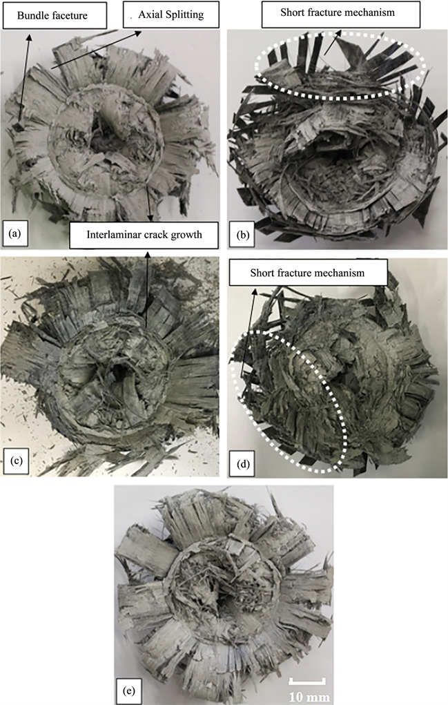
Figure 7. Plane view of crushed axial and off-axis specimens (a) axial; (b) off-axis at 10˚; (c) integrated 45˚ flat chamfer; (d) integrated lay-up sequence and (e) integrated 45˚ flat chamfer with integrated lay-up sequence.
The force-displacement curve (see Figure 8) shows a trend of improved energy absorption from the initial crushing process in cases of (a), (c) and (e) where flat 45˚ chamfer trimming was utilised. Cases of (c) and (e) had similar testing conditions with a variable of lay-up sequence. Integrated lay-up sequence has shown slightly better energy absorption capabilities at off-axis loading in comparison with non-integrated layup design. The trimming mechanisms utilised in cases (a), (c) and (e) had shown better energy absorption capabilities compared to (b) and (d). Cases (a) and (e) both showed a similar trend as both have similar integrated conditions of lay-up and triggering mechanisms. This has clearly indicated the similarity of their failure mechanisms. Both cases eliminate transverse shearing failure mode, which is a common failure fracture mode in off-axis loading conditions.
3.3. Specific Energy Absorption (SEA)
3.3.1. Calculation of Specific Energy Absorption
Specific energy absorption is one of the most important crashworthiness parameter. This parameter determines the energy absorption capability of each specimen regarding their crushed mass, meaning that the absorbed energy per unit of the crushed specimen mass. Referring to Equation (2), the SEA is a function of total work (WT) that represents the energy absorption capability which is equal to the area under the load-displacement curve and crushed specimen mass. Total work done (Equation (1)) is a function of integration of mean crushing load multiplied by the stroke displacement.
(1)
where F is the corresponding force on the structure and s is the cross-head distance.
Specific Energy Absorption (SEA) is energy absorption capability, which is calculated as per unit crushed mass absorbed.
(2)
where m is crushed mass, q is the material density, and v is the volume of crushed specimen.
3.3.2. SEA Results
As the lateral inclination angle increases the specific energy absorption decreases, (see Figure 9). The specimens subjected to axial loading reached an SEA of about 64 kJ/kg, the 5˚ specimens reached SEA of about 54 kJ/kg, 10˚ specimens reached SEA of about 40 kJ/kg, this trend is followed by 28 kJ/kg and 18 kJ/kg for 20˚ and 30˚ off-axis loading conditions respectively. This research focuses on improving energy absorption capability at off-axis loading by tailoring the ply-orientations and 45˚ flat chamfering acting as the trigger to increase specific energy absorption capability. The integrated off-axis at 10˚ showed higher SEA value than all other off-axis angles.
4. Finite Element Modelling
4.1. Basic Consideration
For the simulations, an Explicit FE LS-DYNA code is used with multi-layered shell configuration to reduce numerical cost. Composite tubes were modelled as double layers of Belytschko-Tsay circular shell elements with one integration point in the element plane to represent the direction of the stacking sequence.

Figure 8. Force-displacement of axial and off-axis integration comparison (a) axial; (b) off-axis at 10˚; (c) 45˚ flat chamfer; (d) tailored lay-up sequence and (e) 45˚ flat chamfer with tailored lay-up sequence. Mean Force: (a) 98 kN (b) 62 kN (c) 83 kN (d) 77 kN (e) 98 kN.

Figure 9. Specific energy absorption (SEA) of axial, 5˚, 10˚, 20˚, 30˚, and improved 10˚.
The GFRP innermost shell has six integration points with another six integration points being assigned to outermost shell to represent all twelve UD-layers. Each individual layer has a thickness of 0.25 mm. The total thickness of both shells is 3 mm. Each fibre orientation is assigned with insertion of an integration point in respect to the stacking sequence used with its associated thickness.
4.2. Number of Shell(s) Configuration
The effect of number of shells on the energy absorption prediction of FEM is investigated. The studied cases are, 1 shell, 2 shells, 3 shells, 4 shells, 6 shells, and 12 shells (see Figure 10).
In this study, since the crushed morphology is also one of the factors that is greatly influenced, hence is implemented in Figure 10. From the crushed morphology

Figure 10. Number of shell configuration, (a) 1 shell; (b) 2 shells; (c) 3 shells; (d) 4 shells; (e) 6 shells; (f) 12 shells.
point of view, it can be concluded that, as the number of shells increase, the symmetricity and predication of crushing behaviour improves. Since 12 plies were used in experimental studies, six study cases were considered. All cases were subjected to the same trigger mechanism and applied energy.
In Figure 11, the shell configurations are compared. In single shell configuration, the initial peak and mean crushing force is off by 45%. However, in double shell configuration, this improves to 5% difference. The initial peak value is 80 kN with crushing force of 67 kN. Hereafter, the computational cost is the deciding parameter. Since the crushing behaviour slightly or minimally improves by adding more shells. This improvement is in both initial peak value and mean crushing force value. However, the computational cost increases rapidly by adding more shells to the model. Using 12 shells configuration compared with experimental data, it has 1.5% difference and using double shell configuration has 5% difference. As an engineering point of view, this compromising 3.5% results into solving the problem in 4.5 times less computational costs, one takes 28 hours to converge and the other 123 hours.
At this stage since the main concentration is energy absorption capability, the reliable and cheaper computational cost of double shell configuration is considered in this study, and also supported by [19] [38] [39] .
4.3. FE Model Setup
Quadrilateral Shell element was used with each element size of 2.5 mm × 2.5 mm. The trigger mechanism was modelled by reducing first row thickness of the shell elements to represent the bevel trigger, from 1.5 mm to 0.05 mm in each shell. A solid element rigid block was modelled to represent the striker. LS-DYNA Material model of Enhanced_composite_damage (Mat_54-55), which is an orthotropic material with failure criterion of Chang-Chang was used. This failure criterion is a modification of Hashin’s failure criterion for assessing lamina failure. The hourglass was set at 10% [38] [39] . Refer to Table 1 for GFRP TenCate E722 material properties.

Figure 11. Shell configuration comparison.

Table 1. Material properties of GFRP (TenCate E772).
Modelling interlaminar separation or delamination failure (Mode-I) requires either detailed experimental investigation for cohesive zone or three-dimensional representation that both result into increase of computational and experimental costs. Delamination failure causes energy absorption and this can be modelled with multi-layered shell configuration with a contact card that is capable of GIC implemented energy release rate [38] . Defining One_Way_Surface_To_Surface_Tiebreak contact between the two shells with inner tube being master and outer being slave.
The tiebreak option enables the detachment of the contact surfaces after reaching a maximum normal stress (NFLS) or shear stress (SFLS). Does the failure parameter, driven by occurring normal and shear stresses, become 1, the contact forces soften linearly until contact distance PARAM is reached and the interface failure is completed. Based on the interlaminar utilisation of the contact, the parameters are determined by the mechanical properties of the matrix material. Consequently, shell layers detach when the interlaminar stress exceeds the matrix properties, which are mainly responsible for interlaminar strength. Maximum normal and shear contact stresses for the tiebreak contact are based upon the mechanical properties of the epoxy resin. The maximum contact distance is set to 0.5 mm, refer to Table 2 for all input parameters. Automatic_Node_To_Surface contact was defined for the striker and inner shell with striker being master and inner shell being slave. Automatic_Single_Surface contact algorithm was utilised. This prevents penetration of the crushing tube by its own nodes. In the calibration procedure, parameters DFAILT, DFAILM and DFAILS (shear failure strains) were found to have a marginal effect on the results and were kept constant at arbitrarily selected values of 0.02, 0.02 and 0.03, respectively. However, increasing DFAILM value, increased computational cost unreasonably, and produced unrealistic crushed morphologies, this is due the stacking sequence, when ±45 are used, the matrix split becomes unpredictable (see Figure 12). utilising a stacking sequence of [0]12 has shown effective with realistic axial splits and petal formations (see Figure 13). It was found that simulations with DFAILC = −0.004 and SOFT = 0.75 yielded the mean crushing force value and displacement behaviour for chamfered tubes that matched very well with experimental data.
To satisfy quasi-static conditions, it is important that the load is applied in a manner that would yield a minimal inertial effect on the results and the ratio of the kinetic energy to the internal energy must be reasonably small. Time-scaling was utilised to apply the load in higher rate to reduce total simulation time. A

Figure 12. Specific energy absorption (SEA) (a) quasi-static; (b) impact.
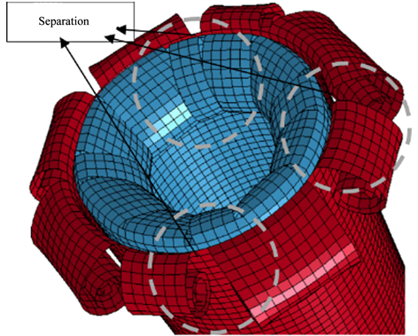
Figure 13. Effect of stacking sequence of [0]12 configuration on petal formation of FEM crushed morphologies.
Table 2. Tiebreak input parameters of GFRP (TenCate E772).
constant loading rate of 0.65 m/s was applied and the kinetic energy to the internal energy were less than 10% upon initial contact and less than 5% throughout the remainder of the crushing process. All bottommost nodes of all shell element layers are constrained in their translational degrees of freedom. All simulation results are smoothed using SAE 300 Hz filter [188].
4.4. FEA Results and Discussion
4.4.1. Axial and Off-Axis Crushing under Quasi-Static Loading
This study experimentally and numerically investigates the structural integrity of GFRP composite tubes against axial and off axis loading under quasi-static loading. Off-axis loading angles of 5˚, 10˚, 20˚ and 30˚ were selected for the study. The results indicated that as the lateral incline angle increases the mean crush force and energy absorption decreases. Axial loading compared with off-axis loading had better energy absorption capability with mean crush force of 100 kN. The experimental (see Figure 3 and Figure 14) morphologies of axial
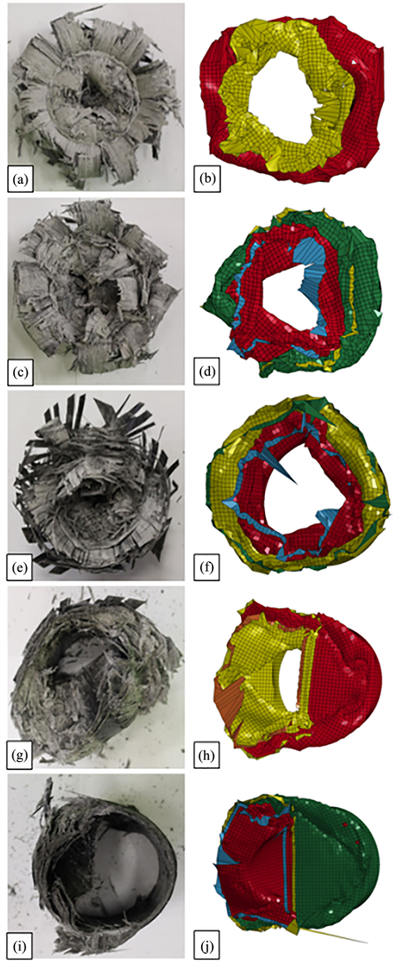
Figure 14. Plane view of crushed axial and off-axis specimens (a) axial experiment; (b) axial FEA; (c) 5˚ experiment; (d) 5˚ FEA; (e) 10˚ experiment; (f) 10˚ FEA; (g) 20˚ experiment; (h) 20˚ FEA; (i) 30˚ experiment; (j) 30˚ FEA.
and off-axis angle 5˚ illustrated bundle fracture and close to brittle failure mechanism which is a combination of lamina bending and transverse shearing modes. Off-axis angle 10˚ showed transverse shearing mode characterised by wedge-shaped laminate cross section with multiple short interlaminar fractures and axial cracks. Off-axis angle 20˚ and 30˚ showed catastrophic failure mechanism with unsymmetrical damaged. This results into minimal energy absorption capability.
Figure 15 represents the various stages of the axial and off-axis loading conditions. Both experiment and FEA in all cases demonstrate a similar crushing behaviour. In respect to morphologies of the crushed tubes, the effect of off-axis and unsymmetrical crushing behaviour shown in Figure 3(d) and Figure 3(e), that showed unsymmetrical inner and outer fronds formation.
The main concentration of this study was based on energy absorption capability on each case. The failure mechanism is a factor of how the energy was absorbed and force-displacement curve indicates the amount of energy absorbed in each case. To compare FEA and experiment, the mean crush force values are compared. Figure 16 shows the intrawall failure mechanisms comparison between experimental results and FEA results, and it can be noted that, a double shell configuration can represent the axial and off-axis crushing behaviour.
Figure 4, shows the five experimental studies at axial and off-axis with angles of 5˚, 10˚, 20˚ and 30˚. It can be concluded from the graph that as the lateral incline angle increases the energy absorption decreases. Figure 17(a) represents force-displacement of GFRP axial crushing. The axial experiment data has a mean crush force of 100 kN with FEA being 98 kN. The mean crush force values of experimental and FEA is very close in all cases. In off-axis 5˚ (see Figure 17(b)) the experimental data has a mean crushing force of 82 kN and FEA is 80 kN. The experiment and FEA difference in mean crush force at 10˚ (see Figure 17(c)) is 2 kN, 61 kN and 59 kN respectively, followed by 3 kN at 20˚ (see Figure 17(d)) with mean crush force of 39 kN and FEA 36 kN respectively. At 30˚ (see Figure 17(e)) the experimental mean crush force is 25 kN and FEA is 22 kN. The experimental and FE analysis are in good agreement and showed similar trending curves with FEA sensitivity towards lateral inclined angles.
4.4.2. Axial Crushing and Improvement of off-Axis Loading
In this section, the integrated off-axis at 10˚ is modelled and simulated. This configuration cancels the off-axis effect and improves energy absorption capability. Various crushing stages of the specimens at off-axis loading is shown in Figure 18 where the experiment and numerical stages are compared. According to the morphologies of crushed tubes (see Figure 19), the effect of ply-orientation and flat trimming were modelled to increase energy absorption capability. By observing both experimental and numerical results, it can be concluded that by altering and tailoring the stacking sequence in respect to composite tube axis and engaging flat trimming in the triggered end of the tube, the energy absorption can be significantly improved. Figure 20 represents the force-displacement

Figure 15. Various stages of axial and off-axis crushing (a) axial FEA; (b) axial experiment; (c) 5˚ FEA; (d) 5˚ experiment; (e) 10˚ FEA; (f) 10˚ experiment; (g) 20˚ FEA; (h) 20˚ experiment; (i) 30˚ FEA; (j) 30˚ experiment.

Figure 16. Crack Propagation at central intra-wall (a) axial experimental failure mechanism; (b) axial FEA; (c) 5˚ experiment; (d) 5˚ FEA; (e) 10˚ experiment; (f) 10˚ FEA; (g) 20˚ experiment; (h) 20˚ FEA.
 (a)
(a)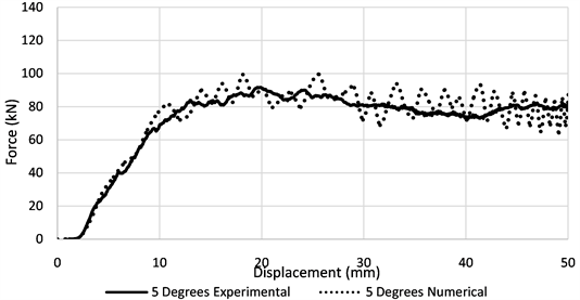 (b)
(b)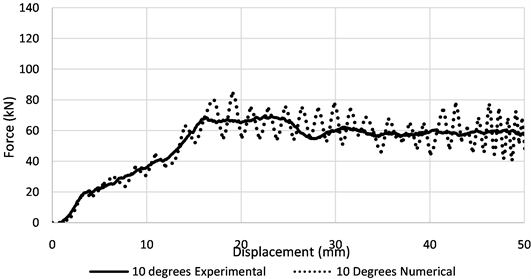 (c)
(c) (d)
(d)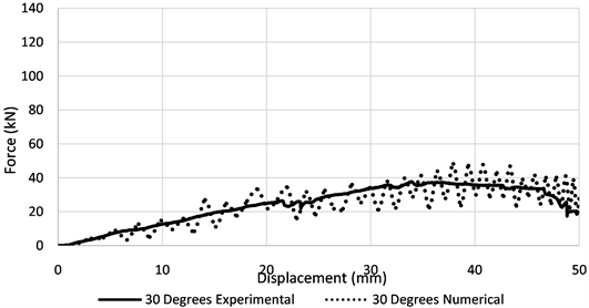 (e)
(e)
Figure 17. Force-displacement of axial and off-axis (a) axial and off-axis experimental comparison; (b) axial experimental and FEA; (c) 5˚ experimental and FEA; (d) 10˚ experimental and FEA; (e) 20˚ experimental and FEA; (f) 30˚ experimental and FEA.
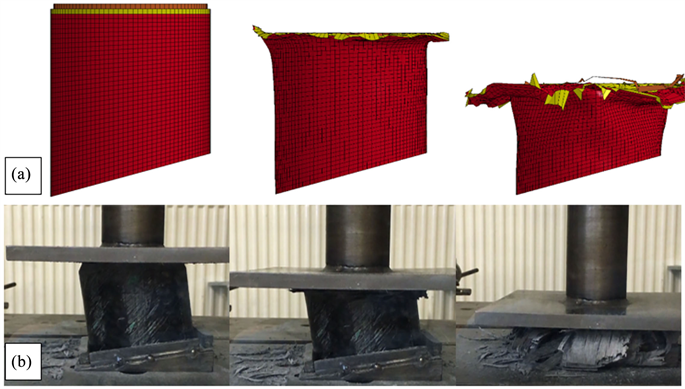
Figure 18. Various stages of integrated off-axis at 10˚ crushing of specimens (a) FEA and (b) experiment.
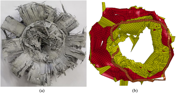
Figure 19. Plane view of crushed integrated off-axis at 10˚ specimen (a) experiment; (b) FEA.

Figure 20. Force-displacement comparison of experimental and numerical of integrated off-axis at 10˚.
history of GFRP integrated specimen and its comparison with the related experimental data. The experimental data has a mean crush force value of 100 kN while the value of the FEA result is 98 kN which shows similar trending curves and high sensitivity towards stacking sequence and trigger mechanism.
5. Conclusions
In the present study, the crashworthiness of composite tubular structures was experimentally investigated under axial and oblique loading. The results have shown that, as the lateral incline angle increases the energy absorption decreases and catastrophic failures were observed at off-axis angles of above 20˚ - 30˚. This conflicts with various previous studies, it was noted from the relative researches that at 10˚ off-axis angle higher energy absorption was observed [19] [24] . This is due to the geometry differences, in previous studies box structures were used and, in this paper, circular tube structures were subjected to investigation. This geometry differences and result into different crushing behaviours.
From a design perspective, the second part focused on improvement of mean crush force and consequently increase of energy absorption capabilities in off-axis loading. It was shown that tailoring ply-orientation can result into increase of mean crush force from 60 kN to 72 kN and consequently increasing energy absorption in 10˚ off-axis angle. All specimens which were subjected to flat trimming showed higher energy absorption in comparison with the original ones. The combination of tailored ply-orientation and flat trimming showed a similar trend as axial loading at 10˚ off-axis loading with both mean crush force of close to 100 kN.
This study helps to increase energy absorption capabilities at various configurations. Cancelling oblique loading effect improves crashworthiness behaviour, and this study has experimentally and numerically showed the possibility of achieving this.
The multi-layered FEM model was developed in LS-DYNA to create a numerical model for further studies of composite structures subjected to axial and off-axis loading. Study of utilising various numbers of shells can be beneficial at substantially increase of computational costs, a balance between the two can be considered and double shell configuration produces high accuracy results and is efficient.
The numerical model is capable of predicting force/displacement curves and crushing behaviors at various configurations with reasonable accuracy. The present study has established sufficient information on the effect of various lateral inclination angles on energy absorption capability and improving crashworthiness behaviours by integrating ply-orientation and altering the trigger mechanism to increase specific energy absorption capability.
Cite this paper
Rabiee, A. and Ghasemnejad, H. (2018) Laminate Tailoring of Composite Tubular Structures to Improve Crashworthiness Design at Off-Axis Loading. Open Journal of Composite Materials, 8, 84-109. https://doi.org/10.4236/ojcm.2018.83008
References
- 1. McGregor, C., Vaziri, R., Poursartip, A. and Xiao, X. (2016) Axial Crushing of Triaxially Braided Composite Tubes at Quasi-Static and Dynamic Rates. Composite Structures, 157, 197-206. https://doi.org/10.1016/j.compstruct.2016.08.035
- 2. Jia, X., Chen, G., Yu, Y., Li, G., Zhu, J. and Luo, X. (2013) Effect of Geometric Factor, Winding Angle and Pre-Crack Angle on Quasi-Static Crushing Behavior of Filament Wound CFRP Cylinder. Composites Part B: Engineering, 45, 1336-1343. https://doi.org/10.1016/j.compositesb.2012.09.060
- 3. Yan, L. and Chouw, N. (2013) Crashworthiness Characteristics of Flax Fibre Reinforced Epoxy Tubes for Energy Absorption Application. Materials & Design, 51, 629-640. https://doi.org/10.1016/j.matdes.2013.04.014
- 4. Mahdi, E., Sahari, B.B., Hamouda, A.M.S. and Khalid, A. (2001) An Experimental Investigation into Crushing Behaviour of Filament-Wound Laminated Cone—Cone Intersection Composite Shell. Composite Structures, 51, 211-219. https://doi.org/10.1016/S0263-8223(00)00132-X
- 5. Palanivelu, S., Paepegem, W.V., Degrieck, J., Ackeren, J.V., Kakogiannis, D., Hemelrijck, D.V., Wastiels, J. and Vantomme, J. (2010) Experimental Study on the Axial Crushing Behaviour of Pultruded Composite tubes. Polymer Testing, 29, 224-234. https://doi.org/10.1016/j.polymertesting.2009.11.005
- 6. Liu, Q., Xing, H., Ju, Y., Ou, Z. and Li, Q. (2014) Quasi-Static Axial Crushing and Transverse Bending of Double Hat Shaped CFRP Tubes. Composite Structures, 117, 1-11. https://doi.org/10.1016/j.compstruct.2014.06.024
- 7. Meidell, A. (2009) Computer Aided Material Selection for Circular Tubes Designed to Resist Axial Crushing. Thin-Walled Structures, 47, 962-969. https://doi.org/10.1016/j.tws.2009.02.003
- 8. Rabiee, A. and Ghasemnejad, H. (2017) Progressive Crushing of Polymer Matrix Composite Tubular Structures: Review. Open Journal of Composite Materials, 7, 14-48.
- 9. Saijod, T.W.L., Said, M.R. and Yaakob, M.Y. (2012) On the Effect of Geometrical Designs and Failure Modes in Composite Axial Crushing: A Literature Review. Composite Structures, 94, 803-812. https://doi.org/10.1016/j.compstruct.2011.09.013
- 10. Reyes, A., Langseth, M. and Hopperstad, O.S. (2003) Square Aluminum Tubes Subjected to Oblique Loading. International Journal of Impact Engineering, 28, 1077-1106. https://doi.org/10.1016/S0734-743X(03)00045-9
- 11. Zeinoddini, M., Harding, J.E. and Parke, G.A.R. (2000) Contribution of Ring Resistance in the Behaviour of Steel Tubes Subjected to a Lateral Impact. International Journal of Mechanical Sciences, 42, 2303-2320. https://doi.org/10.1016/S0020-7403(99)00099-5
- 12. Ahmad, Z., Thambiratnam, D.P. and Tan, A.C.C. (2010) Dynamic Energy Absorption Characteristics of Foam-Filled Conical Tubes under Oblique Impact Loading. International Journal of Impact Engineering, 37, 475-488. https://doi.org/10.1016/j.ijimpeng.2009.11.010
- 13. Nagel, G.M. and Thambiratnam, D.P. (2006) Dynamic Simulation and Energy Absorption of Tapered Thin-Walled Tubes under Oblique Impact Loading. International Journal of Impact Engineering, 32, 1595-1620. https://doi.org/10.1016/j.ijimpeng.2005.01.002
- 14. Han, D.C. and Park, S.H. (1999) Collapse Behavior of Square Thin-Walled Columns Subjected to Oblique Loads. Thin-Walled Structures, 35, 167-184. https://doi.org/10.1016/S0263-8231(99)00022-1
- 15. Reyes, A., Langseth, M. and Hopperstad, O.S. (2002) Crashworthiness of Aluminum Extrusions Subjected to Oblique Loading: Experiments and Numerical Analyses. International Journal of Mechanical Sciences, 44, 1965-1984. https://doi.org/10.1016/S0020-7403(02)00050-4
- 16. Yang, S. and Qi, C. (2013) Multiobjective Optimization for Empty and Foam-Filled Square Columns under Oblique Impact Loading. International Journal of Impact Engineering, 54, 177-191. https://doi.org/10.1016/j.ijimpeng.2012.11.009
- 17. Chen, W.G. (2001) Experimental and Numerical Study on Bending Collapse of Aluminum Foam-Filled Hat Profiles. International Journal of Solids and Structures, 38, 7919-7944. https://doi.org/10.1016/S0020-7683(01)00094-4
- 18. Chen, W., Wierzbicki, T. and Santosa, S. (2002) Bending Collapse of Thin-Walled Beams with Ultralight Filler: Numerical Simulation and Weight Optimization. Acta Mechanica, 153, 183-206. https://doi.org/10.1007/BF01177451
- 19. Ghasemnejad, H. and Hadavinia, H. (2010) Off-Axis Crashworthiness Characteristic of Woven Glass/Epoxy Composite Box Structures. Journal of Reinforced Plastics and Composites, 29, 2306-2330. https://doi.org/10.1177/0731684409347807
- 20. Singace, A.A. and El-Sobky, H. (2001) Uniaxial Crushing of Constrained Tubes, Journal of Mechanical Engineering Science, 215, 353-364. https://doi.org/10.1243/0954406011520760
- 21. Song, H.W. and Du, X.W. (2002) Off-Axis Crushing of GFRP Tubes. Composites Science and Technology, 62, 2065-2073. https://doi.org/10.1016/S0266-3538(02)00152-5
- 22. Czaplicki, M.J., Robertson, R.E. and Thornton, P.H. (1990) Non-Axial Crushing of E-Glass/Polyester Pultruded Tubes. Journal of Composite Materials, 24, 1077-1100. https://doi.org/10.1177/002199839002401004
- 23. Ghasemnejad, H., Hadavinia, H. and Aboutorabi, A. (2010) Effect of Delamination Failure on the Crashworthiness of Hybrid Composite Box Structures. Materials & Design, 31, 1105-1116. https://doi.org/10.1016/j.matdes.2009.09.043
- 24. Ghafari-Namini, N. and Ghasemnejad, H. (2012) Effect of Natural Stitched Composites on the Crashworthiness of Box Structures. Materials & Design, 39, 484-494. https://doi.org/10.1016/j.matdes.2012.03.025
- 25. Rabiee, A. and Ghasemnejad, H. (2016) Effect of Multi Stitched Locations on High Speed Crushing of Composite Tubular Structures. Composites Part B: Engineering, 100, 164-175. https://doi.org/10.1016/j.compositesb.2016.06.068
- 26. Mamalis, A.G., Manolakos, D.E., Ioannidis, M.B. and Papapostolou, D.P. (2005) On the Response of Thin-Walled CFRP Composite Tubular Components Subjected to Static and Dynamic Axial Compressive Loading: Experimental. Composite Structures, 69, 407-420. https://doi.org/10.1016/j.compstruct.2004.07.021
- 27. Greve, L., Pickett, A.K. and Payen, F. (2008) Experimental Testing and Phenomenological Modelling of the Fragmentation Process of Braided Carbon/Epoxy Composite Tubes under Axial and Oblique Impact. Composites Part B: Engineering, 39, 1221-1232. https://doi.org/10.1016/j.compositesb.2008.02.002
- 28. Sun, G., Liu, T., Huang, X., Zheng, G. and Li, Q. (2018) Topological Configuration Analysis and Design for Foam Filled Multi-Cell Tubes. Engineering Structures, 155, 235-250. https://doi.org/10.1016/j.engstruct.2017.10.063
- 29. Luo, H., Yan, Y., Meng, X. and Jin, C. (2016) Progressive Failure Analysis and Energy-Absorbing Experiment of Composite Tubes under Axial Dynamic Impact. Composites Part B: Engineering, 87, 1-11. https://doi.org/10.1016/j.compositesb.2015.10.016
- 30. Song, J. (2013) Numerical Simulation on Windowed Tubes Subjected to Oblique Impact Loading and a New Method for the Design of Obliquely Loaded Tubes. International Journal of Impact Engineering, 54, 192-205. https://doi.org/10.1016/j.ijimpeng.2012.11.005
- 31. Nia, A.A., Nejad, K.F., Badnava, H. and Farhoudi, H.R. (2012) Effect of Buckling Initiators on Mechanical Behavior of Thin-Walled Square Tubes Subjected to Oblique Loading. Thin-Walled Structures, 59, 87-96. https://doi.org/10.1016/j.tws.2012.03.002
- 32. Zhou, C., Jiang L., Tian, K., Bi, X.J. and Wang, B. (2017) Origami Crash Boxes Subjected to Dynamic Oblique Loading. Journal of Applied Mechanics, 84, Article ID: 091006. https://doi.org/10.1115/1.4037160
- 33. Zhou, C., Wang, B., Ma, J. and You, Z. (2016) Dynamic Axial Crushing of Origami Crash Boxes. International Journal of Mechanical Sciences, 118, 1-12. https://doi.org/10.1016/j.ijmecsci.2016.09.001
- 34. Sun, G., Pang, T., Xu, C., Zheng, G. and Song, J. (2017) Energy Absorption Mechanics for Variable Thickness Thin-Walled Structures. Thin-Walled Structures, 118, 214-228. https://doi.org/10.1016/j.tws.2017.04.004
- 35. Li, G., Zhang, Z., Sun, G., Huang, X.D. and Li, Q. (2015) Comparison of Functionally-Graded Structures under Multiple Loading Angles. Thin-Walled Structures, 94, 334-347. https://doi.org/10.1016/j.tws.2015.04.030
- 36. Li, G., Xu, F., Sun, G. and Li, Q. (2015) A Comparative Study on Thin-Walled Structures with Functionally Graded Thickness (FGT) and Tapered Tubes Withstanding Oblique Impact Loading. International Journal of Impact Engineering, 77, 68-83. https://doi.org/10.1016/j.ijimpeng.2014.11.003
- 37. Zarei, H.R. (2015) Experimental and Numerical Crashworthiness Investigation of Hybrid Composite Aluminum Tubes under Dynamic Axial and Oblique Loadings. International Journal of Automotive Engineering, 5, 1084-1093.
- 38. Siromani, D., Awerbuch, J. and Tan, T.-M. (2014) Finite Element Modeling of the Crushing Behavior of Thin-Walled CFRP Tubes under Axial Compression. Composites Part B: Engineering, 64, 50-58. https://doi.org/10.1016/j.compositesb.2014.04.008
- 39. Reuter, C. and Troster, T. (2017) Crashworthiness and Numerical Simulation of Hybrid Aluminium-CFRP Tubes under Axial Impact. Thin-Walled Structures, 117, 1-9. https://doi.org/10.1016/j.tws.2017.03.034