Open Journal of Composite Materials
Vol.2 No.1(2012), Article ID:17040,7 pages DOI:10.4236/ojcm.2012.21002
Falling Weight Impact and Indentation Damage Characterisation of Sandwich Panels for Marine Applications
![]()
1DIEM, Università degli Studi di Bologna, Bologna, Italy; 2Skyron Labdesign, Roma, Italy; 3DICMA, Sapienza Università di Roma, Roma, Italy.
Email: carlo.santulli@uniroma1.it
Received October 13th, 2011; revised December 1st, 2011; accepted December 20th, 2011.
Keywords: Sandwich Laminates; Impact; Indentation; Hysteresis Cycles
ABSTRACT
On three configurations of laminates for nautical use, impact and indentation properties have been compared, in the understanding that these represent two different and significant cases in the laminate service, namely contact with falling body and ramming. All the laminate configurations were fabricated using the same stacking sequence of E-glass mats (of weight 225 and 600 g/m2) as skins, while the core was obtained with different types of rigid PVC foams in the case of A laminate (HEREX C-75) and in that of B and C laminates (COLTH C-55). The latter laminates are also protected with Gelcoat on the outer side. The resin used for A and B laminates was a conventional vynilester (DISTITRON VE 100 SC), while for C laminate a polyester-based including some non-oil derived components was used (ENVIREZ 1807). Laminates of each of the three configurations have been impacted from 1, 1.5 and 2 meters with a 1.25 kg mass using a 12.7 mm hemispherical nose, therefore yielding impact energies of 12.25, 18.37 and 24.5 Joules respectively. Subsequently, other laminates have been quasi-statically indented at with 0.05 mm/s cross-head speed, using the same indentor, until the maximum average displacement obtained during low velocity impact for each configuration and each energy was obtained. The results obtained show that strain rate has an effect on the performance of these laminates. In particular, the improved resistance to penetration appears to occur at the expense of damage dissipation due to vibrations. Quasi-static indentation does not appear to fully reproduce the effect of low velocity impact loading for these sandwich structures, showing significant differences in the hysteresis cycles, both during loading and during the damping phase, which need to be combined with the variable effect of damage on the laminates.
1. Introduction
In a number of real service situations for engineering components, contact with foreign bodies is a common occurrence. In the particular case of marine composites, these are very susceptible to low energy impact, which may occur during construction (e.g., by accidental drops of working tools or during displacement of the different components) or during operation (e.g., due to grounding or to collisions with other crafts, docks or floating debris) [1]. Low velocity impact i.e., resulting neither in penetration nor in significant excitation of plate vibration modes, has a particular importance, in that it can entail quite substantial amounts of damage, which may be around the limit of bare visibility and therefore require decisions about the need for hull repairs.
This decision can be assisted by a number of tests aimed at material characterization when subjected to impact. An impact event is characterised by a quasi-elastic phase of deflection, following by the onset of unrecoverable damage in the form of indentation [2]. The study of impact hysteresis cycles from the force vs. displacement curves allows a partition of absorbed energy in different components (elastic, plastic and damping fractions): also a quasi-linear value can be obtained during loading to the maximum load, often referred to as linear stiffness [3,4].
In particular, hysteresis cycles reflect the fact that in composites the relation of the contact force with indentation responds to different laws during loading and during unloading. At impact energies causing unrecoverable deformation to occur, the difference between energy absorption during loading and energy release during unloading can be exploited to maximise the area of the hysteresis cycle, to work towards the achievement of a higher material damping.
In theory, according to the modified Hertzian law for composites, the contact force F is related during loading to the indentation, or vertical unrecoverable displacement α, produced on the laminate by the law F = kα1.5 [5]. In this law, the parameter k is given by:
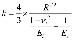 (1)
(1)
where R is the radius of the contact surface of impactor, νi is the Poisson’s ratio of the impactor material, while Ei and Ec are the Young’s modulus in the thickness direction of the impactor material and of the composite laminate, respectively. The variables which change during loading are R and α, which are both growing with increasing contact force, but which are difficult to be measured in real time during loading.
During unloading, a different law has been proposed in [6], which depends on the level of load applied and of the consequent indentation produced at the moment when unloading starts. In particular, in this case the contact force F is obtained as:
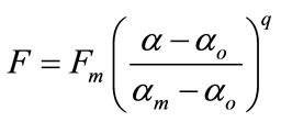 (2)
(2)
where Fm and αm are maximum contact force and maximum indentation, both measured when unloading is started, the exponent q has a value between 1.5 and 2.5, depending on the laminate properties, while αo is the permanent indentation, which may be suggested to be approximately equal to the residual deformation at the end of unloading, when the contact force has come back to zero. As a consequence, during indentation, the exponent q obtained while unloading may be considered an indication of damping properties of the material (the lower q, the more dampened the laminate). In this case, it is questionable whether the values obtained at the end of test can be assumed to be representative of the global damping behaviour i.e., it is unlikely that the values of q will remain about constant during unloading, given the non linearity of this phase.
In some cases, static indentation has been used, as a simulation on a larger timescale of falling weight impact tests of composite materials, offering information on damage characterisation and absorbed energy [7,8]. In particular, in the case of carbon fibre reinforced laminates, penetration energy is substantially unaffected by the loading speed, so that in this specific case impact tests can be substituted by static tests, as far as the measurement of the dent depth is concerned [9]. In contrast, in the case of marine sandwich laminates, however, the response in terms of damping may be complex, depending on boundary conditions [10]. The experimental consequence of this fact is that the hysteresis cycles which are generated during low velocity impact tests and static indentation tests can be substantially different. Each of them will offer information on different aspects of energy absorption during damaging events occurring in service.
The objective of this experimentation is comparing the effect of application of impact loading with that of quasistatic indentation loading, keeping constant the average value of final displacement. This would allow understanding which is the significance of strain rate on the modes of energy absorption produced on the three different sandwich laminates considered, as reflected by impact and indentation hysteresis cycles. The analysis was performed introducing global variables for comparison between the results from the two tests through the study of the respective loading hysteresis cycles.
2. Materials and Methods
2.1. Laminate Configurations Tested
Three different marine laminates, produced by resin infusion in a one-sided close mould, were tested.
These were based on the same stacking sequence, but differing in other aspects. The first one (A laminate) was intended for interior applications and therefore not previously prepared with Gelcoat, the second one (B laminate) was similar to A, but for exposed applications and therefore complete with Gelcoat. The third one (C laminate) was characterised, with respect to the previous two, by the use of an other unsaturated polyester resin, defined hereinafter “bio-resin”, in that it included some non-oil derived materials, namely 17% of soya bean oil and 8% ethanol, in substitution of the vinylester resin used for the previous two laminates, hereinafter defined as “conventional resin”. The materials used for producing the laminates and the respective codes are listed in Table 1, while the different configurations are described in Table 2.
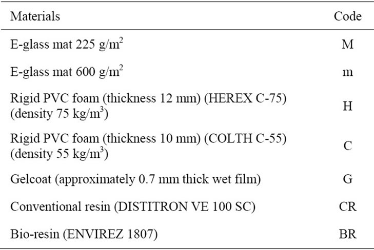
Table 1. Materials used in this study and respective codes.
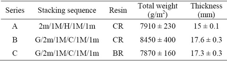
Table 2. Materials used in this study and respective codes.
2.2. Impact System
Impact and indentation tests were carried out using an inhouse built drop-weight impact tower. The impactor diameter was 12.7 mm and its mass was 1.25 kg, which was set to be dropped from a maximum height of 3.3 meters (which is equivalent, given the applied mass, to a theoretical energy of approximately 40 Joules).
Sampling frequency of the signals was 100 kHz with no external filtering.
The variables measured on the drop-weight tower were:
• Contact force, measured using a piezoelectric loadcell for dynamical loading;
• Velocity, measured through elaboration of the signal supplied by a Laser sensor, placed about 5 cm above the quote of the sample;
• Impactor speed and position as a function of time obtained by double numerical integration of force signal (as suggested by ASTM D-7136 standard).
Samples are supported between two steel plates with a central circular opening (diameter 76 mm), realised in accordance with ASTM D-3763 standard, at the centre of which the impact event takes place. In the specific case of these tests, in order not to crush the sandwich laminates, the bolts which constrain the two plates, which are normally serrated with maximum force for composite samples, had been serrated by hand till they allowed no movement of the laminates.
2.3. Testing Procedure
2.3.1. Falling Weight Impact
Five samples each of the three laminates have been first impacted to the maximum possible energy (around 40 Joules), which allowed in all cases penetration. This allowed measuring their impact resistance by the amount of energy which is absorbed, equal to the area of the impact hysteresis cycle (force vs. deflection). This energy is then normalised dividing it by the section of the sample which is left free to deform, equal to d*t, where d is the diameter of the central circular opening in the fixture and t is the laminate thickness. This is a common procedure adopted in IFW testing of composite materials [11,12].
Following this, further five samples for each of the three laminates have been impacted with energies of 12, 18 and 24 Joules. These energies were obtained keeping constant the mass (1.25 kg) and carrying out impact from different heights, namely 1, 1.5 and 2 metres. The respective nominal impact velocities were 4.43, 5.42 and 6.26 m/s. In the case of B and C laminates, impact loading has always been applied on the Gelcoat side of the laminate.
2.3.2. Equivalent Indentation
Indentation tests have been carried out using a servo-hydraulic Instron 8032 testing machine equipped with a 100 kN load cell, in displacement control with 0.05 mm/s crosshead speed. Loading was stopped at the maximum average displacement measured for the relevant impact test (from 1, 1.5 or 2 metres). The diameter of the indenter used was 14.5 mm. In the case of B and C laminates, also equivalent indentation loading has always been applied on the Gelcoat side of the laminate.
3. Results and Discussion
As observed for example in [13], static indentation of composite laminates may be useful, because of the longer timeframe (a few minutes compared to a few milliseconds), to clarify the evolution of impact damage in the material during loading. To simulate service conditions, both testing procedures are useful. Impact puts more emphasis on plastic deformation processes leading to damage, while static indentation is more sensitive to the deviation from linearity during the first phase of loading (before the first load drop takes place), which indicates the proneness of the material to delamination [14].
Initial indications can be supplied by establishing a hierarchy of static mechanical properties of the three laminates. In particular, flexural properties of the laminates show that consistently, both in terms of strength (Figure 1) and in terms of stiffness (Figure 2), the best performance is by far offered by A-laminates, followed by C-laminates, slightly superior to B-laminates.
As far as impact resistance is concerned, this hierarchy appears to be confirmed by the fact that the normalised penetration energy reaches values much higher for the A laminates, approaching as an average 140 kJ/m2 (Figure 3). This value can be considered acceptable and in the order of what has been achieved on laminates of interest for sectors which are very considerate about impact resistance, such as the automotive industry [15,16].
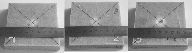
The improved resistance to penetration in A-laminates is visible by comparing Figures 4(a)-(c), the difference being particularly evident when observing the specimens impacted at 24 Joules. When comparing impact hysteresis cycles, the larger vibration of A-laminates is visible from wider load oscillations during the impact event
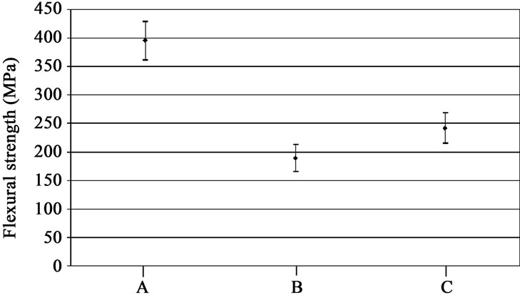
Figure 1. Flexural strength of the laminate configurations.
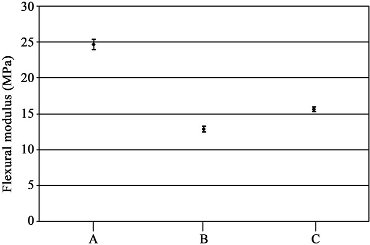
Figure 2. Flexural modulus of the laminate configurations.
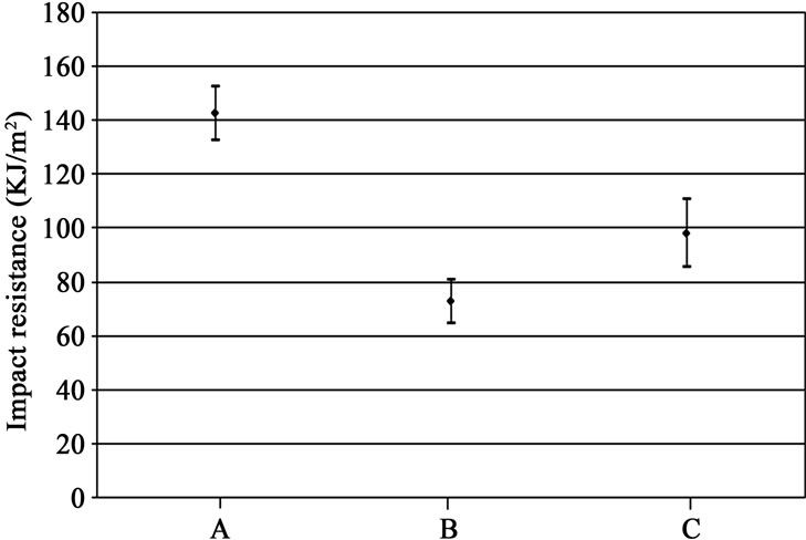
Figure 3. Impact resistance of the laminate configurations.
 (a)
(a)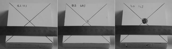 (b)
(b)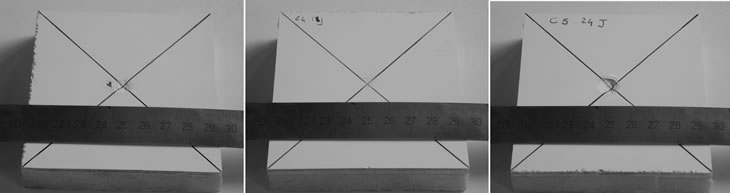 (c)
(c)
Figure 4. (a) Surfaces of A-configuration laminates (impacted at 12, 18 and 24 J); (b) Surfaces of B-configuration laminates (impacted at 12, 18 and 24 J); (c) Surfaces of C-configuration laminates (impacted at 12, 18 and 24 J).
(Figure 5): this can be related to the fact that the coupling between expanded PVC foam and Gelcoat (present in the laminates B and C) may provide a higher protection to the laminate, but at the same time may reduce damage dissipation by vibration. It is also notable that the larger vibrations of A laminates during the elastic part of loading result in a more pronounced load drop at the 24.5 J energy, which is somehow present at the same energy for laminate C, but not visible on laminate B, suggesting possibly some slight degradation in the laminate impacted at high energy to be ascribed to the use of the “bio” resin in the former. With increasing impact or indentation energy, normally plastic energy, connected with damage, increases, hence the surface area of S2 is proportionally growing with respect to S1 and in most cases also with respect to S3, due to the fact that damping effect of the laminate is normally reduced by the presence of damage. This will be discussed also below.
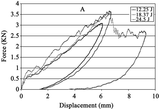
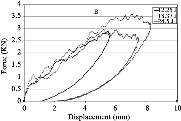
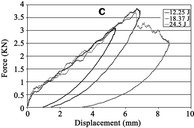
Figure 5. Impact hysteresis cycles.
In Figure 6, how the different variables for analysis of impact hysteresis cycles are measured is clarified. The specific values of the variables are reported in Table 3. The three laminate configurations appear substantially equivalent as regards their linear stiffness and (maximum force/- maximum displacement) ratio (Table 3(a)), which indicates the significance of the plastically absorbed energy S2 with respect to the elastically absorbed energy S1. It can be easily deduced that their mode of impact absorption does not differ much.
Damping ratio (Table 3(b)) decreases with impact severity, because of the presence of damage, which does not allow any more to the whole structure to participate in the rebound process. This decrease is more pronounced for impact at 24.5 J and is very large for A laminates, due to the lower properties of damage dissipation in the absence of Gelcoat coupling, even by a higher thickness of rigid PVC foam, as discussed above.
In the case of indentation tests, the slower rate of loading with respect to impact tests permits to the laminate to more gradually accommodate plastic strain during deformation, resulting in a delayed rebound, as shown in Figure 7. Variables calculated for analysis of indentation tests are described in Figure 8: it needs to be noted in particular that relaxation of the material allowed by longer deformation times does result in a behaviour before reaching the
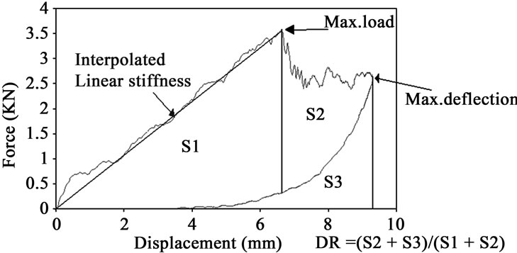
Figure 6. Measurement of the different variables on impact hysteresis cycles.
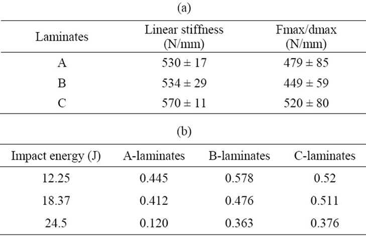
Table 3 (a). Linear stiffness and (maximum force/maximum displacement) ratio for impacted samples; (b) Damping ratio for laminates subjected to impact.
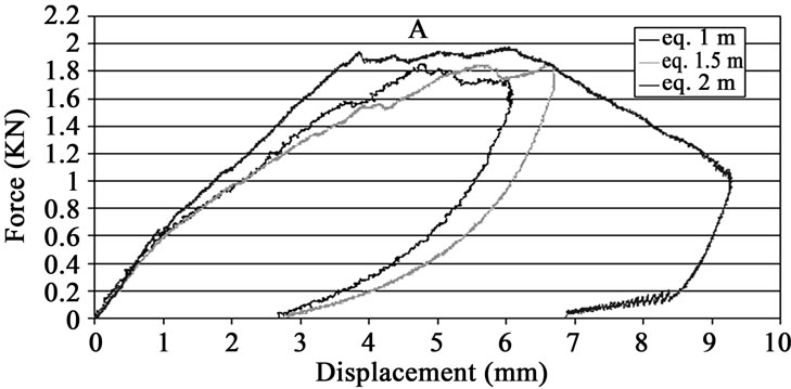
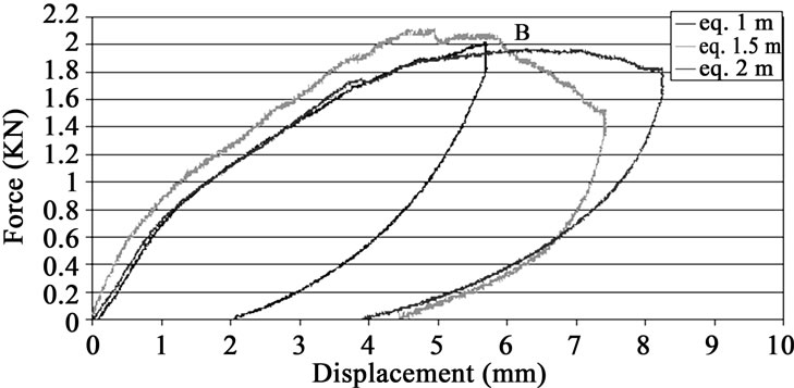
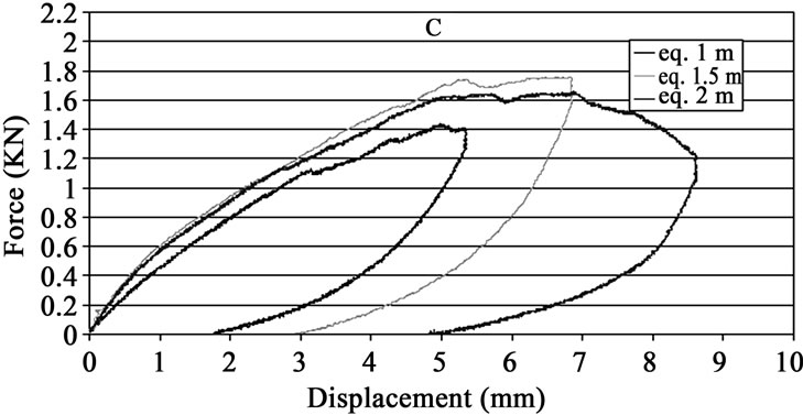
Figure 7. Quasi-static indentation cycles.
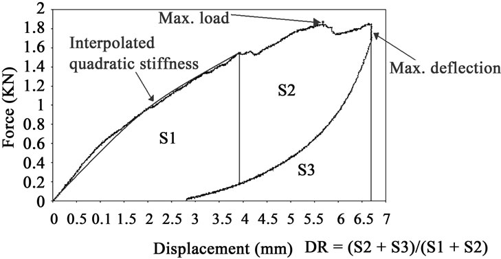
Figure 8. Measurement of the different variables on quasistatic indentation curves.
maximum stress which cannot be defined as fully linear. A second order function, defined as quadratic stiffness, does better describe it, as reported in Table 4, with a considerable goodness of fit, yielding R-squared values superior to 0.99. Quadratic stiffness does appear slightly inferior for C laminates. Once again, from Table 4, the laminates do appear substantially equivalent as regards the partition of absorbed energy in the different terms (elastic, plastic and rebound), as shown by the (Fmax/dmax) ratio.
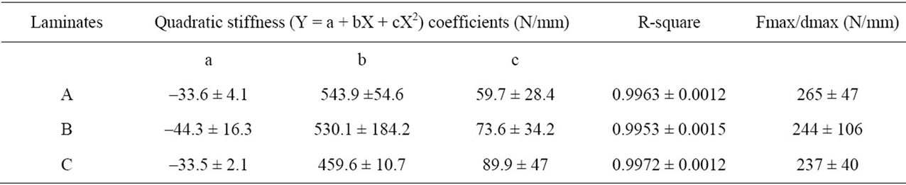
Table 4. Quadratic stiffness, R-square values and (maximum force/maximum displacement) ratio for laminates subjected to quasi-static indentation.
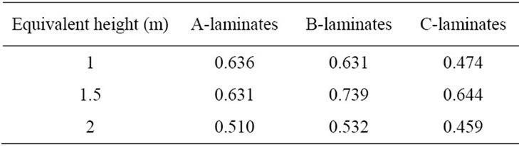
Table 5 Damping ratio for laminates subjected to quasistatic indentation.
Table 5 indicates that damping ratio has not a clear trend with applied energy: this may be referred to the fact that the mode in which evolution from plastic deformation to rebound takes place is specific to the conditions of each laminate during indentation, due to the time allotted while loading the laminate for the internal stresses to distribute and should be investigated further in the future.
The above tests, focused on the production of impact and “equivalent” indentation, demonstrate that the same variables may basically be used in both cases. This confirms the common observation that low velocity impact can be studied using quasi-static indentation, provided the indentor nose, which has been shown to have an influence on the results, is the same for the two types of loading [17].
However, in this case, tests were performed on laminates which are quite similar structurally: here, the comparison between the selected configurations shows significant differences, whether a quasi-static indentation or low velocity impact load is applied, therefore depending on the strain rate. This has been attributed to the fact that vibration is not negligible, especially at the relevant thickness of nautical laminates, and the laws describing them involve possibly complex relationships with the velocity of load application, especially as far as damping (or rebound) is concerned.
4. Conclusions
The results obtained by the comparison of falling weight impact with an equivalent (in terms of measured maximum displacement) quasi-static indentation showed that strain rate has an effect on the performance of these laminates, which appear structurally very similar. In particular, the improved resistance to penetration appears to occur at the expense of damage dissipation due to vibrations. In other words, a compromise between rigidity and capability to effectively withstand contact vibrations is required.
It is also suggested that quasi-static indentation is not always able to reproduce the effect of low velocity impact loading for sandwich structures of thickness in the order of 10 mm or above, including a foam core. This for a twofold reason: first, the lower strain rate of load application brings to non-linear behaviour also during the loading phase of indentation; second, the modes in which damping takes place with the possible impactor rebound have very variable characteristics and are significantly affected by the specific conditions of the laminate, in particular by the presence and severity of damage.
REFERENCES
- L. S. Sutherland and C. Guedes Soares, “Contact Indentation of Marine Composites,” Composite Structures, Vol. 70, No. 3, 2005, pp. 287-294. doi:10.1016/j.compstruct.2004.08.035
- O. I. Benevolenski, J. Karger-Kocsis, K. P. Mieck and T. Reubmann, “Instrumented Perforation Impact Response of Polypropylene Composites with Hybrid Reinforcement Flax/Glass and Flax/Cellulose Fibers,” Journal of Thermoplastic Composite Materials, Vol. 13, No. 6, 2000, pp. 481-496. doi:10.1106/2F7PQW-D06A-MYU6-8692
- C. Santulli, “Study of Impact Hysteresis Curves on EGlass Reinforced Polypropylene Laminates,” Journal of Materials Letters, Vol. 22 No. 22, 2003, pp. 1557-1562. doi:10.1023/A:1026315920448
- C. Santulli and A. P. Caruso, “Effect of Fibre Architecture on the Falling Weight Impact Properties of Hemp/ Epoxy Composites,” Journal of Biobased Materials and Bioenergy, Vol. 3, No. 3, 2009, pp. 291-297. doi:10.1166/jbmb.2009.1037
- S. H. Yang and C. T. Sun, “Indentation Law For Composite Laminates,” ASTM Standard and Engineering Digital Library 787, West Conshohocken, 1982, pp. 425- 449.
- I. H. Choi and C. H. Lim, “Low-Velocity Impact Analysis of Composite Laminates Using Linearized Contact Law,” Composite Structures, Vol. 66, No. 1-4, 2004, pp. 125-132. doi:10.1016/j.compstruct.2004.04.030
- G. Caprino and V. Lopresto, “The Significance of Indentation in the Inspection of Carbon Fibre-Reinforced Plastic Panels Damaged by Low-Velocity Impact,” Composites Science and Technology, Vol. 60, No. 7, 2000, pp. 1003-1012. doi:10.1016/S0266-3538(99)00196-7
- S. H. Lee, Y. Aono, H. Noguchi and S. K. Cheong, “Damage Mechanism of Hybrid Composites with Nonwoven Carbon Tissue Subjected to Quasi-Static Indentation Loads,” Journal of Composite Materials, Vol. 37, No. 4, 2003, pp. 333-349. doi:10.1177/0021998303037004334
- G. Caprino and V. Lopresto, “On the Penetration Energy for Fibre-Reinforced Plastics under Low-Velocity Impact Conditions,” Composites Science and Technology, Vol. 61, No. 1, 2001, pp. 65-73. doi:10.1016/S0266-3538(00)00152-4
- D. K. Rao, “Frequency and Loss Factors of Sandwich Beams under Various Boundary Conditions,” International Journal of Mechanical Engineering Science, Vol. 20, No. 20, 1978, pp. 271-278.
- J. P. Dear and S. A. Brown, “Impact Damage Processes in Reinforced Polymeric Materials,” Composites Part A, Vol. 34, No. 5, 2003, pp. 411-420. doi: 10.1016/S1359-835X(03)00082-4
- H. N. Dhakal, Z. Y. Zhang, M. O. W. Richardson and O. A. Z. Errajhi, “The Low Velocity Impact Response of Non-Woven Hemp Fibre Reinforced Unsaturated Polyester Composites,” Composite Structures, Vol. 81, No. 4, 2007, pp. 559-567. doi:10.1016/j.compstruct.2006.10.003
- F. Xia and X. Q. Wu, “Work on Low-Velocity Impact Properties of Foam Sandwich Composites with Various Face Sheets,” Journal of Sandwich Structures and Materials, Vol. 12, No. 1, 2010, pp. 47-62.
- I. M. De Rosa, C. Santulli and F. Sarasini, “Characterization of Indentation Damage on Carbon/Epoxy Laminates by Means of Acoustic Emission and IR Thermography,” E-Journal of Non-Destructive Testing, Vol. 14, No. 5, 2009.
- C. Santulli, R. Brooks, A. C. Long, N. A. Warrior and C. D. Rudd, “Influence of Materials Processing on Impact Properties of Compression-Moulded Commingled Thermoplastic Composites,” Plastics, Rubber and Composites, Vol. 31, No. 6, 2002, pp. 270-277. doi:10.1179/146580102225004983
- M. Biron, “Thermosets and Composites,” Technology & Engineering, Elsevier, New York, 2004, p. 410.
- E. A. Flores-Johnson and Q. M. Li, “Experimental Study of the Indentation of Sandwich Panels with Carbon Fibre-Reinforced Polymer Face Sheets and Polymeric Foam Core,” Composites Part B, Vol. 42 No. 5, 2011, pp. 1212- 1219. doi:10.1016/j.compositesb.2011.02.013