Journal of Power and Energy Engineering
Vol.03 No.01(2015), Article ID:53018,12 pages
10.4236/jpee.2015.31002
Thermodynamic Performance Analysis of a Gas Turbine in an Equatorial Rain Forest Environment
Barinaadaa Thaddeus Lebele-Alawa, Vining Jo-Appah
Department of Mechanical Engineering, Rivers State University of Science and Technology, Port Harcourt, Nigeria
Email: lebele-alawa.thaddeus@ust.edu.ng
Copyright © 2015 by authors and Scientific Research Publishing Inc.
This work is licensed under the Creative Commons Attribution International License (CC BY).
http://creativecommons.org/licenses/by/4.0/


Received 19 November 2014; revised 22 December 2014; accepted 3 January 2015
ABSTRACT
This paper discusses the thermodynamic analysis of a gas turbine power plant located in the equatorial rainforest of southern Nigeria. Steady state monitoring and direct collection of data from the Mk IV Speedtronics system and log books in the control room was performed. The variation of operating conditions (ambient temperature, compressor discharge temperature, turbine inlet temperature, exhaust temperature and fuel mass flow rate) on the performance of gas turbine (thermal efficiency, net power output, heat rate, specific fuel consumption and compressor work) were investigated using various thermodynamic relations and equations. The results show that a degree rise in ambient temperature could be responsible for the following: 1.37% reduction in the net power output, 1.48% increase in power drop, 1.49% reduction in thermal efficiency, 2.16% increase in heat rate, 2.17% increase in specific fuel consumption and 0.3% increase in compressor work. Furthermore the thermal efficiency decreases by 0.006% for 1 kcal/kWh increase in heat rate and the heat transfer in the hot gas part was found to increase by 0.16% for a degree rise in ambient temperature. Also the work reveals that the gas turbine had a huge drop in power due to influence of site parameters in contrast to designed data.
Keywords:
Gas-Turbine, Thermal Efficiency, Power, Compressor Work, Specific Fuel Consumption, Heat Rate, Combustion

1. Introduction
Gas turbines are designed to be highly effective in producing aligned high thrusts. In a gas turbine, atmospheric air is drawn in through an intake duct into the compressor and delivered at a higher pressure to the combustor. This is accomplished by the gas turbine compressor consisting of a cascade of several stages of blades located in radial form on a single axle [1] -[3] .
The power produced by an expansion turbine and consumed by a compressor is proportional to the absolute temperature of the gas passing through the device. Consequently, it is advantageous to operate the expansion turbine at the highest practical temperature consistent with economic materials and internal blade cooling tech- nology and to operate the compressor with inlet air flow at a temperature as low as possible.
Overall efficiency of the gas turbine cycle depends primarily upon the pressure ratio of the compressor. It is important to realize that in the gas turbine the processes of compression, combustion and expansion do not occur in a single component as they occurred in a reciprocating engine. It is well known that the performance can be qualified with respect to its efficiency, power output, and specific fuel consumption as well as work ratio. There are several parameters that affect its performance including the compressor compression ratio, combustion inlet temperature and turbine inlet temperature [4] .
Thermodynamic analysis of the gas and steam turbines at Takoradi thermal power station has been studied [5] . The work deals with the validation of thermodynamic models that was used to evaluate the performance of this plant using both light crude oil (LCO) and natural gas (NG). The model inputs and outputs included the ambient temperature and pressures, compressor pressure ratio, component efficiencies, air flow rate in compressor, mass of fuel, fuel calorific values, compressor power input, pressure of water in the heat recovery steam generator (HRSG), temperature of flue gas at the exit of the HRSG, temperature of water at the pump input, mass flows of steam and cooling water and the net power from both the gas and steam turbines. Mass and energy balance equations were used for the model development. A work on the analysis of the combustion process of a gas turbine to control temperature has been done [6] . The combustion analysis was carried out to determine combustion chamber exhaust temperature and turbine entry temperature. In the work, three basic factors: excess air, compressor inlet temperature and combustion chamber wall temperature were considered to determine their influence on the com- bustion chamber exhaust temperature with a view to controlling it (combustion chamber exhaust temperature) to tolerable limits with respect to the plants performance and component failure. In analyzing the effects on the combustion chamber exhaust temperature, the temperature profile on the liner was taken into consideration and an equation was developed to describe the temperature profile of the liner using a one dimensional approach. The result shows that the combustion chamber temperature rise increases as the air/fuel ratio increases at constant air inlet temperature.
Analytical modeling of performance characteristics of axial flow two-stage turbine engine using pressure losses models and comparing with experimental results has been done [7] . In this work a detailed systematic analysis of two-stage, axial flow turbine by using different losses models and a new suggestion algorithm based on one- dimensional simulation. To predict the performance of two-stage axial flow turbine at both the design and off- design conditions, one-dimensional modeling, being an accurate and fast method for obtaining gas turbine per- formance condition was used.
Also, numerical simulation of performance of an axial turbine first stage has been studied [8] . The study deals with steady state 2/3D viscous flow to obtain information about the performance of a first-stage axial turbine by simulating the flow through the blades. Computational fluid dynamics software was used to solve the RANS equations with the spalart-Allmaras turbulence model. Performance map for the whole range of operation of tur- bine was constructed. The CFD results were compared with the mean line loss model ones, which account for the losses by Denton loss model.
The effect of surface roughness on thermodynamic performance parameter of axial flow compressor has also been studied [9] . This study respectively discusses the effect of surface roughness on performance parameter when surface roughness is constant and linearly distributed. The study chooses NASA rotor 37 as study object. Reverse design method was applied to reconstruct the fouled compressor by combining laser triangulation sensor with compressor fouling test rig and then reconstructed solid model is imported into ANSYS CFX to simulate flow field.
Other performance analyses have been carried out such as performance analysis and components irreversibility of a (25 MW) gas turbine power plant modeled with a spray cooler [10] . In this work the potential benefits of improving the performance of the current gas turbine plant into a more advanced cycle with high efficiency and power output through inlet air cooling were analyzed. In the study, performance characteristics were determined for a set of actual operational conditions including ambient temperature, relative humidity, turbine inlet temperature and pressure ratio. Operating data for Gas turbine unit were collected from the daily turbine control log sheet for a period of two years. The average operating variables and the thermodynamic properties were determined using Engineering Equation Software (EES). The analysis of the plant was divided into different control volumes and performance of the plant was estimated using component wise modeling. Mass and energy conservation laws were applied to each component and the performance of the plant was determined for the simple system (without spray cooler) and for the cooled system (with spray cooler). The irreversibility rate and the efficiencies of the turbine components were evaluated employing Kotasexergy models. The results obtained showed that the use of a spray cooler on the existing gas turbine cycle gives a better thermal efficiency and less irreversibility rate in the component system and the entire plant.
Also thermodynamic performance analysis of gas turbine power plant has been studied [4] . In this work, the presentation of the parametric study of thermodynamic performance on gas turbine power plant was done. The variation of operating conditions (compression ratio, turbine inlet and exhaust temperature, air to fuel ratio, isentropic compression and turbine efficiency, and ambient temperature) on the performance of gas turbine (thermal efficiency, compressor work, power, specific fuel consumption, heat rate) were investigated. The analytical formula for the specific work and the efficiency were derived and analyzed. The results show that the compression ratio, ambient temperature, air to fuel ratio as well as isentropic efficiencies had strong influence on thermal efficiency.
Thermodynamic appraisal of gas turbine performance in the Niger Delta has also been studied [11] . In this work, the procedure for the study included collation of data from service records, field measurements, simulation of systems and conditions and thermodynamic analysis of results. The results show that a degree centigrade rise in ambient temperature could be responsible for the following: 0.83% reduction in power output, 0.17% increase in heat rate and 0.40% decrease in required air flow rate. Fouling which results in a unit reduction in compressor air flow capacity could yield between half and a unit reduction in compressor isentropic efficiency and the trends tend to follow a linear relationship.
2. Materials and Methods
The research methodology involved collection of data from February 2009 to April 2013 as follows:
1. Monitoring and collection of data from control room Mk IV Speedtronics system;
2. Direct reading of design values from installation document;
3. Field investigation of gas turbine generator during turn around maintenance (TAM);
4. The use of thermodynamic relations and equations for such phenomena that could not be directly measured;
5. Analysis of results obtained;
6. Discussion of results obtained, conclusions and making recommendations.
Each method of data collection was designed to produce facts about some aspects of the work. The data obtained from monitoring of the control room Mk IV Speedtronics system and the daily log sheets were intended to determine those factors that influence the gas turbine thermodynamic process. Two thermodynamic properties― pressure and temperature―stood out as important, as they were measured at the entries and exits of the major components of the gas turbine; namely the compressor, combustion chamber and turbine.
In the treatment and collection of data, mean values of daily parameters were computed by the use of statistical method; followed by monthly average and the overall average for the research period. Some of the phenomena of the operation of the set could not be investigated directly by field measurements because the points were the measurements would have been made where inaccessible. One of such phenomena was the combustion tempera- ture (T3) of the hot gas as it passes through the combustion chamber. This could not be measured directly and as such the parameter was obtained by the use of thermodynamic relations and equations.
The Net Power Output  is the power generated by the generator and is given as:
 (1)
(1)
where  is the shaft work of the turbine and is given as:
 (2)
(2)
where  is mass of product
 ,
,  is specific heat capacity of product,
  turbine inlet temperature. Total heat supplied
 , is calculated from the equation:
 (3)
(3)
 (4)
(4)
where  is mass flow of air,
  is mass flow of fuel,
  is specific heat capacity of air and
  is the calorific value of the fuel. To get T3 for a different fixed amount of fuel supply at each T1, it was therefore necessary to extrapolate.
For steady flow steady state condition, the extrapolation function is given as:
 (5)
(5)
where
 Extrapolated Temperature, ˚K;
 Compressor Exit Temperature, ˚K;
 Actual Temperature at Turbine Inlet for Actual Fuel Supply, ˚K;
 Fixed Fuel Supply, m3/s;
 Actual Fuel Supply, m3/s.
Exhaust Temperature  can be determined as:
 (6)
(6)
where  is isentropic index of compression of air. For the two isobaric processes,
  and
and . Thus the turbine pressure ratio
  is equal to the compressor pressure ratio,
 . With the turbine inlet
temperature  known, exhaust temperature
  can be determined from Equation (6) above.
Compressor Work  of the compressor is given as:
 (7)
(7)
where  is density of air,
  is volume of air aspirated by the compressor,
  is ambient temperature and
  is compressor discharge temperature.
Thermal Efficiency: The gas turbine thermal efficiency  is the percentage of the total fuel energy input that appears as the net work output of the cycle.
 (8)
(8)
where net work is power output and is given as Equation (8) above.
Specific Fuel Consumption (SFC): The ratio of fuel used by a machine to a certain force such as the amount of power the machine produces. And it can be determined by the equation:
 (9)
(9)
where  is fuel mass flow rate (kg/s).
The Heat Rate  is a measure used to determine how efficiently a generator uses heat energy. It can be expressed as:
 (10)
(10)
Stoichiometric Equation: This is the ideal combustion process in which minimum amount of air (stoichiometric or theoretical air) is needed to completely burn a fuel.
 (11)
(11)
Assuming steady-state, steady-flow process involving ideal gasses, we can write from the first law of ther- modynamics applied to combustion as;
 (12)
(12)
where
 = Heat transfer rate in
 ;
;
 = Number of moles of each gas constituents of the reactants;
 =Number of moles of each gas constituents of the product;
 = Heat of formation, in KJ/Kmol;
 = Difference in enthalpy between any given state and the enthalpy at reference temperature at which the heat of formation is taken in KJ/Kmol. This is generally taken at 25˚C (298 K);
 = Work transfer in
 ;
;
 = Summation.
Subscript “P” and “R” indicate “products” and “reactants” respectively.
3. Results and Discussion
The parameters in Table 1 were obtained from the installation document of MS6001B gas turbine.
The values of the turbine inlet temperature in Table 2 were calculated using Equation (4). The parameter in- fluence in terms of ambient temperature on the performance of gas turbine cycle power plant is presented in Tables 1-9. The effects on the operating conditions on the power output, thermal efficiency, heat rate, specific fuel consumption and compressor work were determined and plots are shown in Figures 1-8. In Table 3 the percentage of design power output is gotten by comparing actual power output with the value of the design power output.

Figure 1. Effect of ambient temperature on power output.

Table 1. Design data.
Table 2. Averages of temperature, flow rate and power output (measured).
Table 3. Ambient temperature and turbine inlet temperature and power output.
Table 4. Ambient temperature on thermal efficiency.
Table 5. Ambient temperature on heat rate.
Table 6. Ambient temperature on specific fuel consumption.
Table 7. Ambient temperature on compressor work.
Table 8. Heat rate on thermal efficiency.
Table 9. Ambient temperature and turbine inlet temperature and heat transfer.
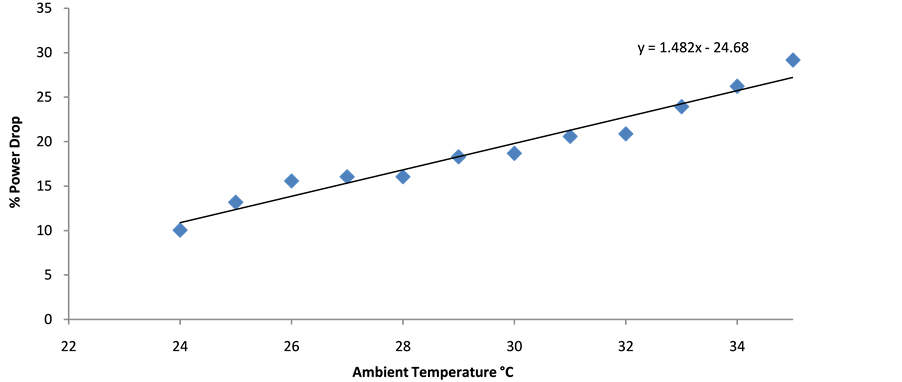
Figure 2. Effect of ambient temperature on power drop.

Figure 3. Effect of ambient temperature on thermal efficiency.

Figure 4. Effect of ambient temperature on heat rate.

Figure 5. Effect of ambient temperature on specific fuel consumption.

Figure 6. Effect of ambient temperature on compressor work.

Figure 7. Effect of heat rate on thermal efficiency.

Figure 8. Effect of ambient temperature on heat transfer.
The governing equation is

Based on Figure 1 and the resultant straight line equation above, it shows that there is a fall in the power output of about 1.37% for every 1˚C rise in the ambient temperature. Translated in real terms it means if a gas turbine operated at an average ambient temperature of 30˚C instead of 15˚C used for the design, there will be a fall in power output of 20.55% or 7.83 Mw for a gas turbine design to generate 38.12 MW at 15˚C.
Based on Figure 2 and the resultant straight line equation above, it shows that there is a rise in the drop of the power output of about 1.48% for every 1˚C rise in the ambient temperature. Translated in real terms it means if a gas turbine operated at an average ambient temperature of 30˚C instead of 15˚C used for the design, there will be a rise in the power drop of 22.2% or 8.46 MW for a gas turbine design to generate 38.12 MW at 15˚C.
For this reason colossal losses are incurred in power generating industries in the tropical regions. To have an idea, let us consider some of the gas turbine power generating sets in the Niger Delta.
Figure 3 above shows that there is a fall in thermal efficiency of about 1.49% for every 1˚C rise in the ambient temperature. Translated in real terms it means that if a turbine set operated at an average ambient temperature of 30˚C instead of 15˚C used for the design, there will be a fall in thermal efficiency of 22.35% or thermal efficiency of 6.33% for a gas turbine designed to produce 28.3%  at 15˚C.
Figure 4 shows that there is a rise in heat rate of about 2.16% for every 1˚C rise in the ambient temperature. Translated in real terms it means that if a turbine set operated at an average ambient temperature of 30˚C instead of 15˚C used for the design, there will be a rise in heat rate of 32.4% or 987.23 kcal/kW×h for a gas turbine designed to generate 3047 kcal/kW×h at 15˚C.
Figure 5 shows that there is a rise in specific fuel consumption of about 2.17% for every 1˚C rise in the ambient temperature. Translated in real terms it means that if a turbine set operated at an average ambient temperature of 30˚C instead of 15˚C used for the design, there will be a rise in specific fuel consumption of 32.55% or 0.092 kg/kWh of fuel for a gas turbine designed to have a specific fuel consumption of 0.283 kg/kWh at 15˚C.
Figure 6 shows that there is an increase in compressor work of about 0.3% for every 1˚C rise in the ambient temperature. Translated in real terms it means that if a turbine set operated at an average ambient temperature of 30˚C instead of 15˚C used for the design, there will be an increase in compressor work of 4.5% or 2 MW for a gas turbine designed to have a compressor work of 45.28 MW at 15˚C.
Figure 7 shows that there is a decrease in thermal efficiency of about 0.006% for every rise in heat rate of about 1 kcal/kW×h. Translated in real terms it means that if a turbine set operated at an average ambient temperature of 30˚C having heat rate of about 3748 kca/kW×h instead of 15˚C as 3047 kcal/kW×h as design, there will be a decrease in thermal efficiency of 22.5%.
Figure 8 shows that there is an increase in the heat transfer of about 0.16% for every rise in ambient temperature. Translated in real terms it means that if a turbine set operated at an average ambient temperature of 30˚C instead of 15˚C used for the design, there will be a rise in the heat transfer of about 2.4%. This in effect means higher temperature in the hot gas part. And where there is insufficient air mass flow in the inlet due to choking of inlet air filters as a result of high dust content in the Niger Delta area, the consequence will be undercooling in the hot gas part.
4. Conclusions
It may be pertinent to state here that though much of the data collected were obtained from the performance records of the MS6001B type gas turbine, the findings can be extended to other types of gas turbines perharps with some little modifications. This is because the processes involved in any open gas turbine are the same―a compression process an approximately constant pressure addition of heat and an expansion process. These pro- cesses also take place in standard equipment namely, compressor, combustion chamber and turbine.
From the data analyses and results obtained, it can be generally said that the climatic condition that is peculiar in the site that was not fully addressed at the time of installation of the gas turbine affected the operations and performance of the set. This particular condition viewed by the author is the high ambient temperature of the area which has a mean daily value of about 30˚C and which varies only slightly on both sides of this value as against the general design ambient temperature of 15˚C. This high ambient temperature is a negative factor and it affects the thermodynamic process of compression, addition of heat and expansion. Apart from affecting the processes, the components in which these processes do occur namely the compressor, the combustion chamber and the turbine can also be physically affected. Petrochemical gas turbine was chosen as a case study for the analysis because it is in the Niger Delta area where all the known larger power generating gas turbines in the country are installed and it is expected that this will not change for some time to come because the fuel for the combustion is abundant in the area. With the foregoing, the gas turbine seems to be the best option for large scale generation of power in Nigeria. Nevertheless, huge amount of loss in power is experienced due to high ambient temperature. Gas turbines are the power of industrial plants in which they are installed in terms of electricity generation within the plant. And as such in order to maintain them at high efficient level. A periodic performance evaluation of the equipment is required.
This work reveals the various parameter and equations used in assessing the performance of the machine and also to check the deterioration of the gas turbine design operation with time by steady monitoring, direct collection of data and using the various thermodynamic relations and equations. The use of micro soft excel is used to obtain the summary of the overall results. The results were compared with the equipment design data. It provides a good method of obtaining the performance of gas turbine.
References
- Lebele-Alawa, B.T., Hart, H.I., Ogagi, S.O.T. and Probert, S.D. (2008) Rotor-Blades’ Profile Influence on a Gas Turbine’s Compressor Effectiveness. Applied Energy, 85, 494-505. http://dx.doi.org/10.1016/j.apenergy.2007.12.001
- Lebele-Alawa, B.T. (2010) Axial Thrust Responses to Gas Turbine’s Rotor-Blade Distortions. Journal of Engineering Physics and Thermophysics, 83, 991-994. http://dx.doi.org/10.1007/s10891-010-0423-2
- Cohen, H., Rogers, G.F.C. and Saravanamuttoo, H.I.H. (1998) Gas Turbine Theory. 4th Edition, Addison Wesley Long- man Ltd., London.
- Rahman, M.M., Thamir, K.I. and Ahmed, N.A. (2012) Thermodynamic Performance Analysis of Gas Turbines Power Plant. Journal of the Physical Sciences, 6, 3539-3550.
- Charles, M., Abeeku, B.H. and Seth, P.A. (2010) Thermodynamic Analysis of the Gas and Steam Turbine at Takoradi Thermal Power Station. Journal of Technology and Advanced Engineering Research, 1, 62-72.
- Odubo, E.O. (1997) Air Flow Regulator for Gas Turbine Combustion Chamber Temperature Control. Master of Technology Dissertation, Rivers State University of Science and Technology, Nigeria.
- Javaniyan, J., Eftari, M., Kaliji, H.D., Ghadak, F. and Rad, M. (2013) Analytical Modeling of Performance Characteristics of Axial Flow Two-Stage Turbine Engine Using Pressure Losses and Comparing with Experimental Results. Journal of Applied Science, 21, 1250-1259.
- Vinicius, G.M., Edson, L.Z., Claudia, R.A. and Lima, R.C. (2012) Numerical Simulation of Performance of an Axial Turbine First Stage. Journal of Aerospace Technology, 4, 175-184. http://dx.doi.org/10.5028/jatm.2012.04025411
- Huadong, Y. and Hong, X. (2013) The Effect of Surface Roughness on Thermodynamic Performance Parameters of Axial Flow Compressor. Journal of Applied Science, Engineering and Technology, 5, 4458-4463.
- Fidelis, I.A., Ikpi, U.U. and Dodoye, I.I. (2012) Performance Analysis and Components Irreversibities of a (25 MW) Gasturbine Power Plant Moduled with a Spray Cooler. Journal of Engineering and Applied Services, 5, 35-41.
- Hart, H.I. (1998) Thermodynamic “Appraisal of Niger Delta Gas Turbine Performance”. Ph.D. Dissertation, Mechanical Engineering, University of Nigeria, Nsuka.
Nomenclature
 Specific Heat at Constant Pressure of Air J/kg×K
 Specific Heat at Constant Pressure of Combustion Products J/kg×K
HR Heat Rate kcal/kW×h
m Mass Flow Rate kg/s
P Pressure N×m2 or bar
 Ambient Pressure bar
 Compressor Outlet Pressure bar
 Turbine Inlet Pressure bar
 Turbine Outlet Pressure bar

 Isentropic Index of Compression of Air

 Isentropic Index of Expansion of Combustion Products
SFC Specific Fuel Consumption kg/kW×h
t Temperature ˚C
T Absolute Temperature ˚K
 Ambient Temperature (Compressor Inlet Temperature) ˚K
 Compressor Exit Temperature ˚K
 Isentropic Compression Outlet Temperature ˚K
T3 Turbine Inlet Temperature ˚K
 Isentropic Expansion Outlet Temperature ˚K
V Volume Flow Rate m3/s
Wc Compressor Work kJ/kg
W Power Output
MW Megawatts
 Isentropic Index of Compression or Expansion
 Isentropic Index of Compression of Air
 Isentropic Index of Expansion of Combustion Product
 Efficiency
 Density of Air kg/m3