Journal of Materials Science and Chemical Engineering
Vol.2 No.3(2014), Article ID:43892,7 pages DOI:10.4236/msce.2014.23002
Ionic Group Derivitized Nano Porous Carbon Electrodes for Capacitive Deionization
Marc Andelman
Mespilus Inc., Worcester, USA
Email: mespilus@charter.net
Copyright © 2014 by author and Scientific Research Publishing Inc.
This work is licensed under the Creative Commons Attribution International License (CC BY).
http://creativecommons.org/licenses/by/4.0/


Received 25 January 2014; revised 25 February 2014; accepted 5 March 2014
ABSTRACT
Capacitance for electrostatic adsorption forms primarily within a Debye length of the electrode surface. Capacitive carbon electrodes were derivatized with ionic groups by means of adsorbing a surfactant in order to test the theory that attached ionic groups would exclude co-ions and increase coulombic efficiency without the need for an added charge barrier membrane. It has been discovered that capacitive electrodes surface derivatized with ionic groups become polarized and intrinsically more coulombically efficient.
Keywords:Capacitive Deionization; Flow Through Capacitor; Polarized Electrode; Nanoporous Carbon; Derivitized Carbon Electrodes; Deionization; Desalination; Water Purification; Ionic Groups

1. Introduction
Pairs of oppositely chargeable high capacitance, high surface area carbon electrodes, known as a flow through capacitor [1] , or capacitive deionization have been previously described for use in water deionization, desalination of brackish water, and water purification. An electric potential or voltage is applied to terminals connected to capacitive electrodes via underlying current collectors. Positive and negative ions present in water electrostatically attract to and electrostatically adsorb onto the opposite polarity electrodes and adsorb as charge. The adsorbed ions are removed from a solution flowing between or through the electrodes, to form a purified stream. The voltage used is below the voltage for electrochemistry to occur. In a true flow through capacitor, the current that drives the ions in this process is therefore due to non faradaic capacitive charging. When the flow through capacitor is fully charged, it may be shunted or reversed in polarity in order to release the adsorbed ions to form a concentrated waste. The outlet flow forms a series of alternating purification and concentration cycles may be diverted by a valve to separate purified and waste streams.
Flow through capacitors utilizes high capacitance electrodes. Such materials have high pore volume in order to achieve high surface areas necessary for high capacitance. Ions from the feed solution diffuse into the pore volume. The pore volume counter-ions electrostatically adsorb onto the electrode and take up capacitance. The pore volume co-ions are simultaneously expelled from the electrode and contaminate the feed solution in the spacer. These processes interfere with the removal of ions from the flow spacer. Therefore, the coulombic efficiency, “ ”, with which the product water is purified, is lowered. This coulombic efficiency is defined as the coulombs of ionic charge adsorbed from flow spacer feed solution, manifested as purified product water, as the coulombs of electronic charge measured as current over the charging purification time. The equation for coulombic efficiency is given by Equation (1).
 (1)
(1)
Qi, the ions usefully removed from the flow spacer feed stream to form purified product water, is given in Equation (2) below as a function of total adsorbed ions adsorbed and the pore volume ions.
 (2)
(2)
Substituting Equation (2), Equation (1) becomes
 (3)
(3)
Qtotal is the total coulombs of ions adsorbed as charge onto the electrode. Qpore, the coulombs of ions present in the pore volume, which originates and diffuses from the ions in the feed solution, is given in Equation (4) in terms of , the molarity of feed solution ions, F, Faraday’s constant, and
 the electrode pore volume.
 (4)
(4)
It therefore follows Equations (3) and (4) that the coulombic efficiency is inverse to both the pore volume, and to the feed solution ion concentration. Therefore, the coulombic efficiency tends towards unity at low feed solution concentrations and therefore low Qpore.
A second generation technology known as the “charge barrier flow through capacitor” [2] , also known as membrane capacitive deionization, and recently being introduced to market, eliminated the coulomobic inefficiency problem [3] , thereby offering higher energy efficiency and high water recovery, of 85% [4] or higher. The so-called “charge barrier” employs ion exchange membranes. These membranes are costly, take up space, and add a resistive layer that decreases flow rate. Additionally, the charge barrier is a cause of concentration polarization [5] , yet another resistive barrier. Water splitting due to concentration polarization is also well known to form hydroxyl ions, leading to fouling and membrane degradation. Capacitance of the capacitive electrode materials is also affected by and directly proportional to electrolyte concentration [6] . Both the non membrane and the charge barrier flow through capacitor therefore suffer from lowered capacitance due to the non optimal concentration of typical feed solutions serving as the electrolyte.
Polarized Electrode Flow through Capacitor
It has been discovered that capacitive electrodes derivatized with ionic groups become polarized and intrinsically coulombically efficient. The polarized electrode flow through capacitor represents the third generation of capacitive deionization technology, after flow through capacitors without, and more recently with, the charge barrier membranes.
A flow through capacitor is a capacitor of the so called “double layer type”. The double layer in this context of a charged electrode refers to the layers of electrostatic charge to which the ions attract and adsorb. These layers include a surface charge layer and a diffuse layer, also known as Stern and Gouy Chapman layers according to models. The total thickness of these layers comprising this so called double layer corresponds to the Debye Length. The electric field strength is very steep in this region, for example on the order of 10^9 Volts per meter. The Debye length estimated in Equation (5) for the case of a univalent salt as follows:
 (5)
(5)
Where
 is the Debye length;
 is the dielectric constant of the solute;
 is the permittivity of free space;
 is Boltzmann’s constant;
 is the absolute Temperature in Kelvins;
 is the elementary charge;
 is Avogadro’s number;
 is the valence of the solute ion;
 is the ionic concentration in the solute in moles/m3.
The Debye length under typical feed water conditions is of the same order of magnitude as the pore thicknesses in many carbon materials used for capacitor electrodes. For example, the Debye length for a 0.01 M NaCl solution is approximately 2 nanometers, and that of a 0.1 M NaCl solution is approximately 0.7 nanometers. The double layer volume can therefore occupy a significant or a majority proportion of the total pore volume of micro and meso porous capacitive deionization electrodes.
The Debye length defines the region where the solute ionic charge is perturbed from the value in the bulk solution, to where counter-ions adsorb and co-ions are adsorbed or expelled, and where capacitance develops. Therefore, it is theorized that attachment of ionic groups within this Debye length region will, by electrostatically, exclude co-ions from the crucial, capacitance forming region of the pore volume, will cause the electrode to become intrinsicallycoulombically efficient, without need for a charge barrier membrane.
2. Experimental
A high capacitance activated carbon powder electrode held together with approximately 5% fibrillated PTFE binder was made according to standard techniques [7] . These electrodes were further modified into cation and anion derivitized electrodes by soaking in separate surfactant solutions at room temperature. Surfactants have hydrophobic tails which irreversibly adsorb onto carbon [8] , thereby serving as an easy and useful means to introduce ionic groups. For this experiment, sodium dodecyl sulfate (SDS) was chosen as an anionic surfactant with which to attach the attached anionic groups to form a negative electrode, and hexadecyltrimethylammonium (HDTMA) bromide was chosen as the cationic surfactant with which to attach the attached cationic group to form a positive electrode. In order to form the polarized electrodes, the carbon electrodes were soaked in solutions of one half the critical micelle concentration of these surfactants. Accordingly, a 1.19 gram/liter solution of SDS, and a 0.17 gram per liter of HDTMA, were separately dissolved in an aqueous solution of 0.1 M NaCl. Carbon electrodes were soaked in these solutions for one month, with occasional stirring. After the soaking period, the electrodes where thoroughly washed in water. The resulting electrodes were used to form a polarized electrode flow through capacitor. Figure 1 shows the relative arrangement of material layers in the polarized electrode flow through capacitor cell, including the flow spacers, positive and negative electrodes and current collectors. The electrodes were a thickness 0.3 millimeters, of 0.7 grams dry weight each, cut as 76 millimeter diameter circles with a 6 millimeter central flow hole. Flow spacers were a woven nylon material 0.1 millimeters thick, with a 30% open area, cut in circles the same size as the electrodes. The current collectors were a 0.4 millimeter thick graphite foil, also cut in circles the same size as the electrodes, but with extending tabs. These tabs were bundled into electrical leads and compression attached to a wire by means of a washer, nut and bolt. The entire electrode assembly consisted of 10 flow spacers, 10 graphite foil current collectors, and 20 electrode layers. There were 18 electrode layers with double sides with respect to the current collector, and two end electrodes with single sides. The electrode layers totaled 14 grams dry weight of surface area capacitive carbon. Half of these electrodes were derivitized with SDS, and the other half with HDTMA, assembled in opposing pairs with respect to the flow spacer. These electrode material layers were held together under compression onto the current collectors and flow spacers into a flow through capacitor cell by means of opposing flat, 100 mm square, 6 mm thick PVC end plates with screws threaded through corner holes. A flow outlet was formed by the alignment of the central material holes and a threaded central hole in one PVC end plate. The flat disc cell design used in this example was similar to that described in typical radial flow, flat stacked flow through capacitor designs [9] . The relative arrangement of layers is depicted in Figure 2.
A schematic showing the arrangement of anode and cathode layers with their bound ionic groups is shown in
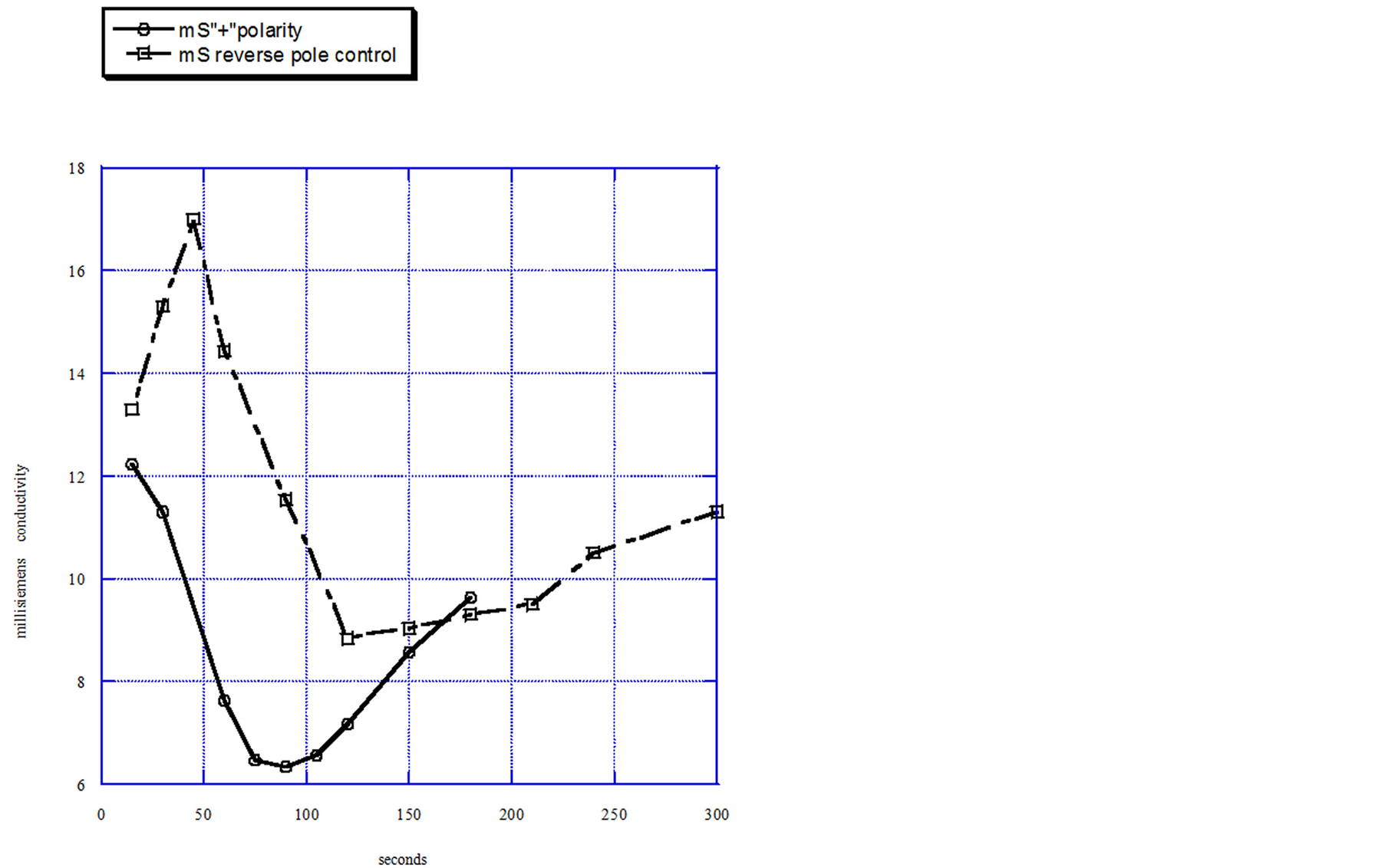
Figure 1. Negative polarity, 1.2 volts, with flowing 0.01 M NaCl solution.
To obtain the purification performance data shown in Figure 4, the entire flow through capacitor cell, with its parallel layers of flow spacer exposed on the sides, was dropped into a 1 liter container of feed solution. A 0.1 M NaCl feed was sucked through the exposed sides of the cell by a tubing pump at a flow rate of 20 milliliters per minute. To apply an electrical potential of 1.2 volts, the cell leads were connected to a DC power supply. The polarity applied to the electrodes was “positive”, defined as the same polarity as the ionic groups. Simultaneous product solution conductivity measurements under positive or negative polarity were taken by a flow through conductivity cell. An otherwise exactly similar flow through capacitor cell, without the ionic group derivatization, was used as a scientific control with which to obtain comparative data and tested under identical feed, flow, and voltage conditions.
To obtain the results shown in Figure 1 the polarized electrode flow through capacitor was charged under identical feed and flow conditions in both the positive, and in the negative polarity, in order to compare the behavior under these two conditions.
To obtain the results shown in Figure 5, an electrical impedance spectrograph was taken with a Gamry Instrument Co. model PC4 Potentiostat/Galvanostat/ZRA, using CMS100 Software, to show how impedance varies with the frequency with which the polarity is switched. A 0.1 M NaCl solution was used under static flow conditions.
Coulombs of ionic charge where calculated from the integral of the purification curve conductivity measurements, over the charge time of the capacitor. Coulombs of electronic charge were calculated from the integral of amperage measured over time. Coulombic efficiency was calculated from the ratio of ionic charge absorbed to coulombs of electronic charge. Capacitance was calculated from the Coulombs of electronic charge divided by the capacitor terminal voltage.
The coulombic efficiency of the polarized electrode flow through capacitor cell, charged in the positive polarity, was 70%, with a product solution electrosorptive capacity of 10.5 mg/gram carbon, and a capacitance of 20.5 Farads per gram .The scientific control capacitor without the attached ionic groups had a coulombic efficiency of 45%, a product solution electrosorptive capacity of 6.3 mg/gram carbon, and a capacitance of 17.5 Farads per gram.
3. Discussion
The attachment of ionic groups onto the electrode pore volume surfaces, within the Debye length, theoretically prevents the infiltration of co ions through the electrostatic process of Donnan exclusion, and electrically biases the pore volume. If this theory is true, a differential purification behavior with regards to electrode applied polarity should be expected. When a charge opposite to the fixed ionic groups is applied to the electrodes, counter-ions move freely into and out of the electrode to adsorb as charge onto the electrode pore surfaces. Upon simple shunting to zero voltage, the flow through capacitor releases surface charge adsorbed ions. When polarity is reversed from positive to negative, so that a like charge to that of the fixed ionic groups is applied to the electrodes, the ionic groups, attached their flexible tails, can attract to the electrode and adsorb as charge. This allows the counter ions to the fixed ionic groups to be expelled. The expulsion of counter ions during negative po-
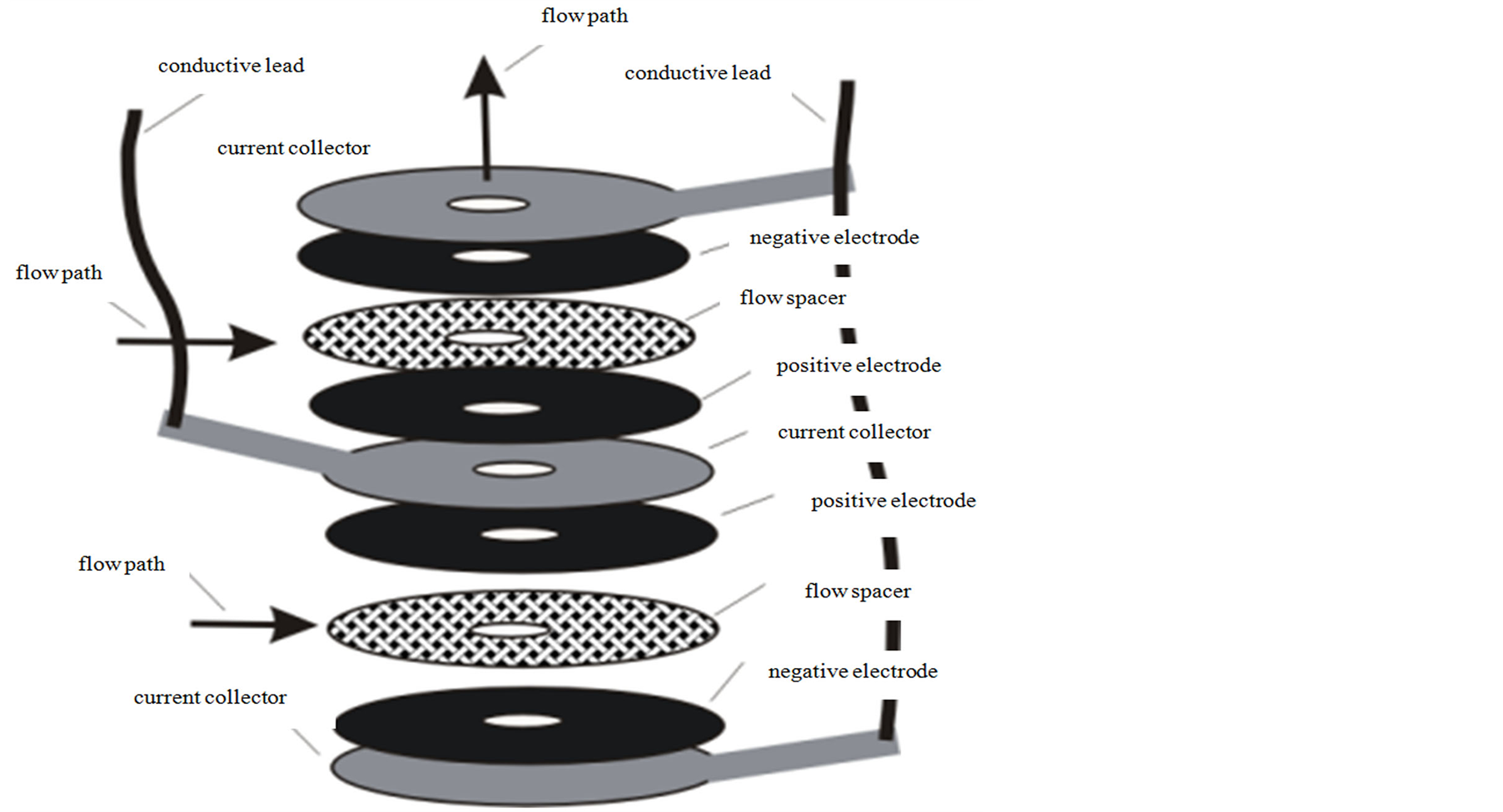
Figure 2. Material layers in polarized electrode flow through capacitor.
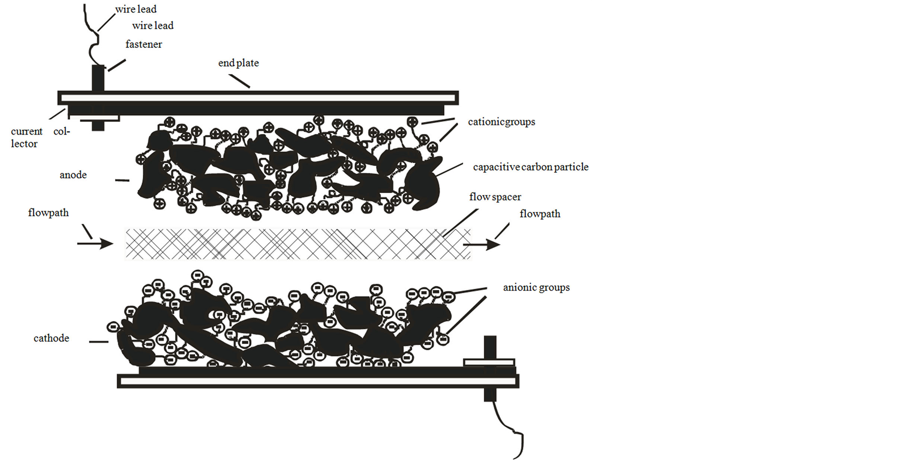
Figure 3. Schematic of anode and cathode with their ionic groups.
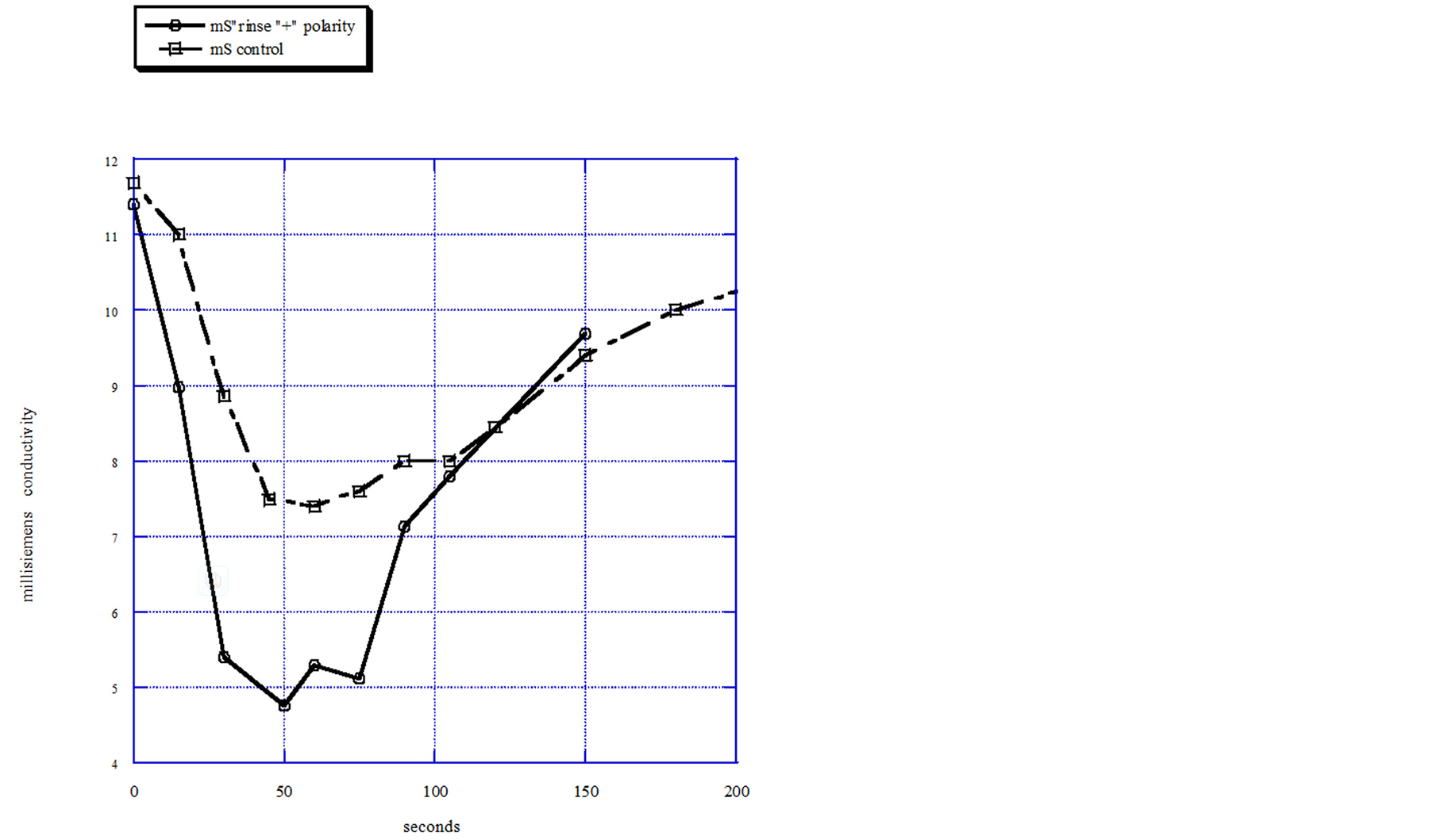
Figure 4. Positive polarity 1.2 volts with flowing 0.01 M NaCl solution.

Figure 5. Electrical impedance spectrograph of polarized electrode capacitive cell.
larity is observed as a concentrated peak, compared to the positive polarity purification, shown in the Figure 4 data. This demonstrates that a flow through capacitor with opposing electrodes containing oppositely charged attached ionic groups, is polarized with respect to purification of ions from a solution. Because co-ions have been excluded, coulombic efficiency is high, compared to the control capacitor, without need for the charge barrier membranes. In addition, the fixed ionic groups raise the effective ionic concentration within the electrode pores, and may also have increased capacitance somewhat. The increase in coulombic efficiency and any increased capacitance are reflected in the increased purification curve shown in Figure 3 of the polarized electrodes as compared to the capacitor without ionic groups. A 0.1 M NaCl feed was chosen as the feed solution because this represents fairly concentrated brackish water, a condition where coulombic inefficiency gets worse due to the greater amount of ions in the pore volume. From the standpoint of practical usage, charging frequencies of a flow through capacitor are low; under 1 Hz. Figure 5 shows a slightly increased low frequency impedance for the derivitized electrode in the positive polarity compared to both the control and the negative polarity case. The reason for the peak of impedance for the negative polarity case at high frequency is unknown. However, this may be indicative of the relaxation time of adsorbed molecular ionic groups moving about on their tethers, and support that supposition that the fixed ionic groups are indeed adsorbing as charge in this polarity.
This work is presented as a proof of principal. Future work on the effect of the attached ionic groups on capacitance and coulombic efficiency as a function of ionic group and pore characteristics will be welcome.
4. Conclusion
Ionic group derivatizing nanoporous carbon exhibits polarized purification and electrical behavior in a capacitive deionization cell. This supports the theory that attaching fixed charges within the Debye length of the electrode pore volume will bias the electrode by excluding co ions and by favoring counterions. This polarized electrode represents a new class of capacitive deionization electrode materials for coulomb efficiency without charge barrier membranes.
References
- Andelman, M.D. (1998) The Flow through Capacitor: A New Tool in Wastewater Purification. Filtration Separation, 35, 345.
- Andelman, M.D. (2004) Charge Barrier Flow through Capacitor. US6709560.
- Andelman, M. (2011) Flow through Capacitor Basics. Separation and Purification Technology, 80, 262-269. http://dx.doi.org/10.1016/j.seppur.2011.05.004
- Lee, L.Y., Ng, H.Y., et al. (2009) Integrated Pretreatment with Capacitive Deionization for Reverse Osmosis Reject Recovery from Water Reclamation Plant. Water Research, 43, 4769-4777. http://dx.doi.org/10.1016/j.watres.2009.08.006
- Biesheuvel, P.M. and van der Wal, A. (2010) Membrane Capacitive Deionization. Journal of Membrane Science, 346, 256-262. http://dx.doi.org/10.1016/j.memsci.2009.09.043
- Conway, B.E. (1999) Electrochemical Supercapacitors: Scientific Fundamentals and Technological Applications. Springer. http://dx.doi.org/10.1007/978-1-4757-3058-6
- Solomon, F. (1983) Method for Forming an Electrode Active Layer or Sheet. US4379772.
- Hei, H.H. (2006) Adsorption of Ionic Surfactants on Active Carbon Cloth. Masters of Chemical Engineering Thesis, Hong Kong University, Hong Kong.
- Andelman, M.D. (1997) Non-Fouling Flow-Through Capacitor. US5620597.