Open Journal of Acoustics
Vol.05 No.02(2015), Article ID:56986,19 pages
10.4236/oja.2015.52005
A Study on the Mode Shape Piezoelectric Motor
Jwo Ming Jou
Department of Mechanical Engineering, Cheng Shiu University, Kaohsiung City, Taiwan
Email: k0556@gcloud.csu.edu.tw
Copyright © 2015 by author and Scientific Research Publishing Inc.
This work is licensed under the Creative Commons Attribution International License (CC BY).
http://creativecommons.org/licenses/by/4.0/


Received 17 April 2015; accepted 5 June 2015; published 9 June 2015
ABSTRACT
In this paper, we try to use the coating of effective electrode surface and change the direction of polarization to design the mode shape piezoelectric motors of the first three modes. We also compare the gain of the mode shape piezoelectric motors with respect to the normal shape piezoelectric motor, including rotational speed, loading ability, torque, phase angle conversion and efficiency. According to the results of theoretical and simulation analysis, we have found that the gain of the mode shape piezoelectric stators are larger than the normal shape piezoelectric stator on average. According to the results of experiments, we found that the gain of the rotational speed, loading ability, torque, driving phase angle conversion and efficiency of the mode shape (MS1 - 3) piezoelectric motors are higher than the normal shape piezoelectric motor (NS) under driving condition of the second vibration mode. Also, the gain of the rotational speed and loading ability of the mode shape 2 (MS2) piezoelectric motor are higher than other shapes piezoelectric motors (NS, MS1 and MS3) under driving condition of the second vibration mode. The used maximum rotational speed of the mode shape 2 (MS2) piezoelectric motor is up to 946 rpm under conditions of 180 Vp-p driving voltage, 10.7 kHz driving frequency, 0˚ driving phase angle and 13.0 gw net weight. The maximum loading ability and torque of the mode shape 2 (MS2) piezoelectric motor is respectively 451 gw and 0.91 mkgw-m under conditions of 180 Vp-p driving voltage, 10.7 kHz driving frequency, 0˚ driving phase angle and 173 rpm rotational speed. And the gain of efficiency (output power) and maximum loading ability (torque) of the mode shape 2 (MS2) piezoelectric motor are respectively 2.28 and 1.54 with respect to the normal shape piezoelectric motor under conditions of 180 Vp-p driving voltage, 10.7 kHz driving frequency and 0˚ driving phase angle. According to the results of the experiments, we have finally found that the piezoelectric motors (NS and MS1 - 3) can be driven only by the second vibration mode because the stator can produce elliptical motion and allows the rotor to generate orientation rotation. However, the first vibration mode can allow the rotor to be rotated very fast but it can’t make the rotation of the rotor orientation. Furthermore, we also found that the rotor can’t rotate by the third vibration mode because its vibration energy is absorbed by the structure itself, so causing the rotor stagnation.
Keywords:
Mode Shape (MS), Normal Shape (NS), Piezoelectric Motor, Piezoelectric Stator, Gain

1. Introduction
The main object for study is a mode shape piezoelectric motor and its comparison object is the normal shape piezoelectric motor in this paper. Its appearance is similar to the tubular piezoelectric motors or ultrasonic motors. For comparison, the found experimental data are listed in Table 1 [1] - [10] . The main difference between the normal shape and mode shape piezoelectric motor lies in the different coating method of effective electrode surface. Due to the normal shape, the tubular piezoelectric motors have many advantages, including small size, fast rotational or movement speed and response, high torque or high loading ability. So they are very useful for optical and electro-mechanical systems. For example, they may be applied to autofocus system of the optical lens, and let them to be embedded within the camera or mobile phones. Also, they are the main transmission mode generated by the actuating force or frictional force of the piezoelectric stator to drive the rotor in order to rotate or slide movement. The size of the actuating force or frictional force depends on the composition of the stator and motor, the coating of effective electrode surface, and driving conditions. The tubular piezoelectric motor was first described in 2002 [1] . It is primarily a metal tube on both sides of two piezoelectric ceramic affixed. The stator size is D2.4 mm × L10 mm. The maximum angular or rotational speed of tubular piezoelectric motor is 60 rad/s or 573 rpm under conditions of 120 Vp-p driving voltage and 69.5 kHz driving frequency. And the maximum torque, output power and efficiency are 1.8 mNm, 60 mW, and 25% respectively. The following year, a smaller tubular piezoelectric motor has been proposed for publication [2] , which size of the stator is D1.6 mm × L6 mm. But the maximum angular or rotational speed is only 45 rad/s or 430 rpm under conditions of 100 Vp-p driving voltage and 131.8 kHz driving frequency. And the maximum torque, output power and efficiency are 0.5 mNm, 45 mW and 16% respectively. Then again the next year, another smaller tubular piezoelectric motor is proposed [3] , which size of the stator is D0.8 mm × L2.2 mm. The maximum rotational speed is up to 3850 rpm under conditions of 40 Vp-p driving voltage and 70.0 kHz driving frequency. But the maximum torque and loading are only 25 nNm and 0.5 mN respectively. In 2005, a miniature tubular piezoelectric motor is published [4] , which size of the stator is D4.0 mm × L5.0 mm. The maximum rotational speed is up to 4000 rpm under conditions of 25 Vp-p driving voltage and 67.0 kHz driving frequency. But the maximum torque is only 1.6 μNm. In 2006, another miniature tubular piezoelectric motor is proposed [5] , which size ratio of L/D of the stator is 3.50. The maximum rotational speed is only 385 rpm under conditions of 200 Vp-p driving voltage and 49.4 kHz driving frequency. And the maximum torque is 3.1 Nm. In 2007, another one miniature tubular piezoelectric motor is published [6] , which size of the stator is D4.0 mm × L5.0 mm. The maximum rotational

Table 1. The performance comparison of the tubular piezoelectric motors [1] -[10] .
speed is up to 9600 rpm under conditions of 30 Vp-p driving voltage and 314.5 kHz driving frequency. But the maximum torque is 5.5 μNm. In 2009, a metal tube type piezoelectric motor is applied to push the optical lens [7] , which size of the stator is D3.0 mm × L12.0 mm. The maximum rotational speed is 2075 rpm under conditions of 140 Vp-p driving voltage and 62.0 kHz driving frequency. And the maximum loading is 420 mN. In 2011, a single vibration mode tubular piezoelectric motor is published [8] , which size of the stator is D6.6 mm × L25.4 mm. The maximum rotational speed is 400 rpm under conditions of 100 Vp-p driving voltage and 23.5 kHz driving frequency. But the maximum torque is only 0.3 mNm. Next year, a rotary-linear piezoelectric motor is proposed [9] , which size of the stator is D12.0 mm × L55.0 mm. The maximum movement speed is only 11 mm/s under conditions of 150 Vp-p driving voltage and 19.7 kHz driving frequency. But the maximum torque is up to 500 mN. Recently, a tubular piezoelectric motor is proposed [10] , which size of the stator is D5.0 mm × L15.0 mm. The maximum rotational speed is only 208 rpm under conditions of 100 Vp-p driving voltage and 97.0 kHz driving frequency. But the maximum torque and loading are only 3.6 μNm and 5.0 mN. At this point, we can find that the tubular piezoelectric motors have characteristics of high speed and low torque or low speed and high torque. However, if the torque or loading of the tubular piezoelectric motor is too small, then a big speed is still not being applied to for optical or electro-mechanical systems. Therefore, the appropriate composition, size, torque, loading ability and rotational or movement speed of the tubular piezoelectric motor must be carefully considered.
2. The Composition and Operation Principle
In this paper, the composition and operation principle of the normal shape and mode shape piezoelectric motors as shown Figures 1-3. Wherein the composition of the normal shape or mode shape piezoelectric motors which includes a piezoelectric stator and a rotor. The piezoelectric stator is composed of a metal tube and four piezoelectric ceramics which have the normal shape and mode shape effective electrode surface, as shown Figure 1 and Figure 3. And the full size of the stator piezoelectric is 50 mm × 7.4 mm × 7.4 mm. In operation, as long as to drive the piezoelectric stator by appropriate frequency and voltage, to make the free end of stator generate elliptical trajectory, thereby to push the rotor rotates, as shown Figure 2.
As for the coating method of effective electrode surface of the mode shape piezoelectric ceramics are based on the vibration modes of the cantilever beam or piezoelectric stator, shown as Figure 4. In which the equation of dimensionless vibration modes  as follows:
 . (1)
. (1)
where the dimensionless eigenvalues  and parameters
  are defined as:
 . (2)
. (2)
and
 . (3)
. (3)
As for the effective electrode surfaces  of the normal shape and mode shape piezoelectric ceramics can be defined as:
 . (4)
. (4)
Because of the high frequency vibrations are easily absorbed by the structure itself, so we only focus on the first three vibration modes and effective electrode surfaces of the mode shape piezoelectric ceramics, as shown Table 2 and Figure 5.
3. Equation of Motion
The equation of motion of the normal shape and mode shape piezoelectric stator can be obtained from the previous paper as follows [11] :

Figure 1. The composition of the normal shape or mode shape piezoelectric motor.

Figure 2. The operation principle of the normal shape or mode shape piezoelectric motor.

Figure 3. The oblique view of the normal shape and mode shape piezoelectric motors.

Figure 4. The first three vibration modes and effective electrode surface of mode shape piezoelectric stator.

Figure 5. The first three vibration modes and effective electrode surfaces of the mode shape piezoelectric ceramics.
Table 2. The first three vibration modes and effective electrode surfaces of the mode shape piezoelectric ceramics.
where .
.
 . (5)
. (5)
and
 . (6)
. (6)
where the definition of constants in the above Equation (5)-(6) as follow:
 . (7)
. (7)
 . (8)
. (8)
 . (9)
. (9)
 . (10)
 . (11)
where in above the symbols of  are defined as the Young’s modulus, bending stiffness constant per unit width, an arbitrary frequency, the resonance frequency, thickness, piezoelectric charge constant, transverse driving voltage, transverse displacement, time, longitudinal coordinate, transverse coordinate, density, the angle velocity of arbitrary frequency, the angle velocity of resonance frequency, the eigenvalues of arbitrary frequency and the eigenvalues of resonance frequency.
Furthermore we can find the general solution of mode shape and normal shape piezoelectric stator from the previous paper as follow [11] :
 . (12)
and
 . (13)
where above constants can be determined by the following electro-mechanical boundary conditions:
 . (14)
and
 . (15)
Let Equation (12) and Equation (13) are substituted into Equation (14) and Equation (15), we can get the transverse displacement solution of the first three vibration modes of free end of the normal shape and mode shape piezoelectric stators on xz-plane as follow:
 . (16)
and
 . (17)
where the eigenvalues ,
,  and
and  and
and .
.
Similarly, we can get the solution of vertical displacement of the first three vibration modes of the normal shape and mode shape piezoelectric stators at of free end on xy-plane as follow:
 . (18)
and
 . (19)
Under steady-state operating mode, above Equation (16-19) can be rewritten as follow:
 . (20)
 . (21)
 . (22)
and
 . (23)
where  is defined as driving phase angle. And
  representative amplitude of the normal shape and mode shape piezoelectric stators at the transverse and vertical direction respectively.
In order to get an elliptical trajectory of the normal shape and mode shape piezoelectric stators at the free end, we can make driving phase angle difference 90˚ or use a different driving waveforms under different sides of piezoelectric stators. Therefore, above Equations (23)-(24) can be rewritten again as follow:
 . (24)
and
 . (25)
Follow by, we can get an elliptical trajectory of the normal shape and mode shape piezoelectric stators at the free end on the zy-plane from Equations (20)-(21) and Equations (24)-(25), shown as Figure 6.
If we further consider the effect of axial or horizontal vibration on the normal shape and mode shape piezoelectric stators, then above equations can be rewritten as again:
 . (26)
 . (27)
 . (28)
and
 . (29)

Figure 6. The elliptical trajectory of the normal shape or mode shape piezoelectric stator on xz-plane and xy-plane.
where the axial or horizontal vibration displacement of the normal shape and mode shape piezoelectric stators as follow:
 . (30)
and
 . (31)
wherein  and
and  representative amplitude of the normal shape and mode shape piezoelectric stators at axial or horizontal direction respectively.
So far, we can get an oval ball of the normal shape and mode shape piezoelectric stators at the free end, as follow:
 . (32)
and
 . (33)
In fact,  and
and  for 3D piezoelectric stators.
4. Gain and Efficiency
In this paper, we can get the gain of vertical and transverse displacement or velocity ( or
or ) of the normal shape and mode shape piezoelectric stators or motors from Equations (24)-(27) under the same driving conditions, as follow:
 . (34)
or
 . (35)
and
 . (36)
or
 . (37)
So for, we can predict the gain of the normal shape and mode shape piezoelectric stators from Equations (34)-(37) under the same driving conditions.
In addition, the conversion efficiency of the normal shape and mode shape piezoelectric stators or motors can be defined as:
 . (38)
where the definition of the input power as:
 . (39)
and the definition of the output power as:
 . (40)
where  representative the modal resonance frequency, frictional force, input driving current, radius of rotor, rotational speed, torque, input driving voltage, weight or loading of rotor, the modal angle velocity, dynamic friction coefficient and efficiency of the normal shape and mode shape piezoelectric stators or motors.
5. Case Study―Theoretical Analysis, Simulation Analysis and Experiments
In this paper, we have to understand the differences and gain between the normal shape and mode shape piezoelectric motors or stators, in particular, through theoretical analysis, simulation analysis and experiments to validate. And the material properties are used in the analysis and the experimental procedure, as shown in Table 3.
wherein the step of the theoretical analysis is as follows:
(5-1-1) Using the simple approximate solution of one-dimensional spatial structure to do analysis, and only do a comparative analysis of dimensionless vibration displacement or velocity by Equations (38-39).
(5-1-2) Using the minimum frequency spacing ( ) to analyze the gain of the first three modes of the mode shape and normal shape piezoelectric stators from 1 kHz to 40 kHz.
As for the simulation analysis procedure is as follows:
(5-2-1) Modeling of the mode shape and normal shape piezoelectric stators respectively, including select element type, enter the physical properties, as well as coordinate system conversion, as shown Figure 7.
(5-2-2) Meshing of the mode shape and normal shape piezoelectric stators respectively, including select the most sophisticated cutting of mesh or select the smart size 1, as shown Figure 8.
(5-2-3) Simulation Analysis: Solving of the mode shape and normal shape piezoelectric stators respectively, including setting boundary conditions of electro-mechanical, as shown Figure 9. All of which driving voltage on the effective electrode surface is 1.0 V.
(5-2-4) Post-processing of the mode shape and normal shape piezoelectric stators respectively, includes processing the first three modes, the maximum deformation or electric potential, as shown Figures 10-13.
As regards the experimental step is as follows:
(5-3-1) Cutting the piezoelectric ceramics with the effective electrode surface, and making the piezoelectric stators of normal shape and mode shape, shown as Figure 14.
(5-3-2) Using the dual channel arbitrary function generator (Model: A-303, AA Lab. Systems Ltd. Co.) and
Table 3. The material properties and size of piezoelectric stator.

Figure 7. Modeling and setting the material properties of the normal shape and mode shape piezoelectric stators.

Figure 8. Meshing the material properties of the normal shape and mode shape piezoelectric stators using the most fine mesh.
the power amplifier (Model: AFG-3022, Tektronix Co.) to drive the normal shape and mode shape piezoelectric motors, shown as Figure 15.
(5-3-3) Using the digital tachometer (Model: RM-1501, TES Electrical Electronic Co.) and the sound level meter (Model: TES
(5-3-4) Using the loading test weight and rotors to test the loading ability of the normal shape and mode shape piezoelectric motors, shown as Figure 16. Which the material of the loading test weight or mass is aluminum and copper. Their size and weight are D50 mm ´ H10 mm and 53 gw or 165 gw. And the material of the rotor is

Figure 9. Defined loads or setting boundary conditions of electrode-mechani- cal of the normal shape and mode shape piezoelectric stators under clamped- free mechanical boundary conditions and 1.0 Vp-p driving voltage electrical boundary conditions.

Figure 10. The first three vibration modes of the normal shape piezoelectric stators on the yz plane using 3D Materials.
copper. Its size and weight are D15 mm ´ H10 mm and 13 gw. Due to the material of metal tube of the piezoelectric stator is aluminum, and the material of rotor is copper. So the dynamic friction coefficient of metal tube and rotor is about 0.22 - 0.27 or . As for the transform coefficient of Equation (42) must be determined after the experiment, it is usually much less than 1.0 or
 .
.

Figure 11. The first three vibration modes of the mode shape 1 piezoelectric stators on the yz plane using 3D Materials.

Figure 12. The first three vibration modes of the mode shape 2 piezoelectric stators on the yz plane using 3D Materials.
6. Results and Discussion
According to the results of theoretical analysis, simulation analysis and experiments, we found:
1) Under conditions of theoretical analysis of one-dimensional (1D) approximation solution and using the
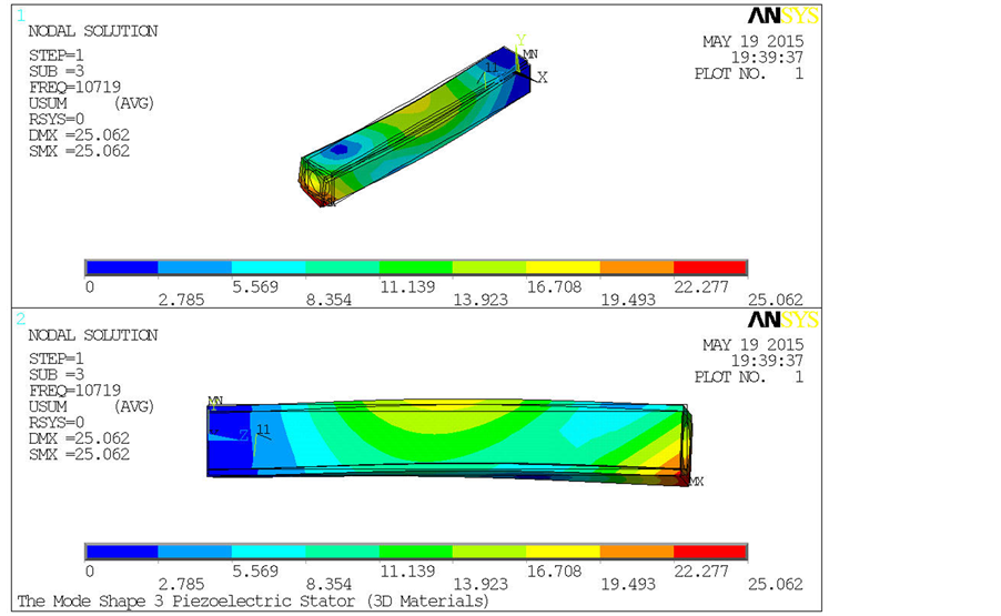
Figure 13. The first three vibration modes of the mode shape 3 piezoelectric stators on the yz plane using 3D Materials.

Figure 14. The piezoelectric ceramics and stators of the normal shape and mode shape.
minimum frequency spacing of 1Hz, the gain of the maximum dimensionless vibration displacement or velocity of the all mode shape 1 - 3 (MS1 - MS3) piezoelectric stators are far than the normal shape (NS) piezoelectric stator, as shown Figure 17 and Table 4. Where the mode shape 3 (MS3) piezoelectric stator has

Figure 15. The experimental structure of the normal shape or mode shape piezoelectric motor.

Figure 16. The normal shape and mode shape piezoelectric motors.

Figure 17. The gain and dimensionless vibration displacement or velocity of the first three modes of the normal shape and mode shape piezoelectric stators by 1D approximate solution.
Table 4. The gain of the maximum dimensionless vibration displacement or rotational speed of the normal shape and mode shape piezoelectric stators under conditions of theory analysis, simulation analysis and experiments.
Note: Th.: Theoretical Analysis; Si.: Simulation Analysis; Ex.: Experiments; N.A.: Represents the rotation direction of the rotor can not be determined.
the largest gain which is about 20.06. Followed by, the gain of the mode shape 1 (MS1) piezoelectric stator is about 19.70. Furthermore is the gain of the mode shape 2 (MS2) piezoelectric stator is about 3.33.
2) Under conditions of using the 1D material properties to simulate the 3D piezoelectric stators, the gain of the maximum dimensionless vibration displacement or velocity of the first three modes of the mode shape 1 (MS1) piezoelectric stator is larger than other type (NS, MS2 and MS3) piezoelectric stators. Where the gain of the third vibration mode of the mode shape 1 (MS1) piezoelectric stator with respect to the normal shape (NS) piezoelectric stator is about 1.40, as shown in Table 4.
3) Under conditions of using the 2D material properties to simulate the 3D piezoelectric stators, the gain of the maximum dimensionless vibration displacement or velocity of the all mode shape 1 - 3 (MS1 - MS3) piezoelectric stators are larger than the normal shape (NS) piezoelectric stator. Where the gain of the orthogonal modes of the mode shape 1 - 3 (MS1 - 3) piezoelectric stators with respect to the normal shape (NS) piezoelectric stator are 1.30, 1.40 and 1.50, as shown in Table 4.
4) Under conditions of using the 3D material properties to simulate the 3D piezoelectric stators, the gain of the maximum dimensionless vibration displacement or velocity of the all mode shape 1 - 3 (MS1 - MS3) piezoelectric stators are larger than the normal shape (NS) piezoelectric stator on average. Where the gain of the orthogonal modes of the mode shape 1 - 3 (MS1 - 3) piezoelectric stators with respect to the normal shape (NS) piezoelectric stator are 1.20, 1.30 and 1.50, as shown in Table 4.
5) According to the results of experiments, shown as Figure 18 and Figure 19 and Table 4, we found the normal shape (NS) and mode shape 1 - 3 (MS1 - MS3) piezoelectric motors can be driven by the second vibration mode only, because the second vibration mode can allow the stator to produce elliptical motion, and allow the rotor to generate orientation rotation. And we also found the gain of rotational speed of the mode shape 2 (MS2) piezoelectric motor is higher than other shapes piezoelectric motors (NS, MS1 and MS3) under driving condition of the second vibration mode. Where the gain of rotational speed of the second vibra-

Figure 18. The gain and the rotational speed of the normal shape and mode shape piezoelectric motors under conditions of 180 Vp-p driving voltage, 1.0 - 40 kHz driving frequency and 13 gw net weight.

Figure 19. The real motion state of the normal shape and mode shape piezoelectric motors.
tion mode of the mode shape 1 - 3 (MS1 - 3) piezoelectric stators with respect to the normal shape (NS) piezoelectric stator are 1.19, 1.31 and 1.29, as shown Table 4. In addition, the gain of rotational speed of the first vibration mode can’t be determined. Although we observed that the rotational speed of rotor is very fast, but we also found that the direction of rotation of the rotor to be volatile. Therefore, the rotational speed of rotor of all type (NS and MS1 - MS3) piezoelectric stators is treated as zero under driving condition of the first vibration mode. Furthermore, the gain of rotational speed of all type (NS and MS1 - MS3) piezoelectric stators are zero under driving condition of the third vibration mode. Because its vibration energy is absorbed by the structure itself, so causing the rotor stagnant.
6) Shown as in Table 5, we can find the output power and efficiency of the mode shape 2 (MS2) piezoelectric motor is higher than other type (NS, MS1 and MS3) piezoelectric motors under conditions of 0˚ driving phase angle, 180 Vp-p driving voltage, 13 gw net weight, maximum loading and different dynamic friction coefficient ( and
and ) and the driving frequency of the second vibration mode. Where the maximum output power of the piezoelectric motors (NS, MS1, MS2 and MS3) is respectively 10.18 mW, 23.25 mW, 23.26 mW and 18.00 mW. And where the efficiency of the piezoelectric motors (NS, MS1, MS2 and MS3) is respectively 0.04%, 0.09%, 0.09% and 0.07%. In addition, the gain of the maximum output power or efficiency of the mode shape piezoelectric motors (MS1 - 3) is respectively 2.28, 2.28 and 1.77 with respect to the normal shape piezoelectric motor (NS) under conditions of 0˚ driving phase angle, 180 Vp-p driving voltage, maximum loading,
  different dynamic friction coefficient and the driving frequency of the second vibration mode.
7) Shown as in Table 6, we have found that the maximum torque and gain of the mode shape 2 (MS2) piezoelectric motor is higher than other type (NS, MS1 and MS3) piezoelectric motors under conditions of 180 Vp-p driving voltage, maximum loading, different dynamic friction coefficient ( and
and ) and the driving frequency of the second vibration mode. Where the maximum torque of the piezoelectric motors (NS, MS1, MS2 and MS3) is respectively 0.59 mkgw-m, 0.81 mkgw-m, 0.91 mkgw-m and 0.70 mkgw-m. And where the gain of the maximum torque or loading of the mode shape piezoelectric motors (MS1 - 3) is respectively 1.36, 1.54 and 1.18 with respect to the normal shape piezoelectric motor (NS) under conditions of 0˚ driving phase angle, 180 Vp-p driving voltage, maximum loading,
  different dynamic friction coefficient and the driving frequency of the second vibration mode.
8) Shown as in Figure 20, we found the noise level increase, represents the piezoelectric motors are entering into best vibration mode. One of the biggest noise level in the second vibration mode are about 107 - 110 dB.
9) Shown as in Figure 21, we can find the conversion efficiency of driving phase angle of the mode shape 2 (MS2) piezoelectric motor is higher than other type (NS, MS1 and MS3) piezoelectric motors. On the whole, the conversion efficiency of driving phase angle of the mode shape 1 - 3 (MS1 - MS3) piezoelectric motor is higher than the normal shape (NS) piezoelectric motor.
10) Shown as in Figure 22, we can find the loading ability of the mode shape 2 (MS2) piezoelectric motor is higher than other type (NS, MS1 and MS3) piezoelectric motors. And loading ability of the mode shape1 - 3 (MS1 - MS3) piezoelectric motor is higher than the normal shape (NS) piezoelectric motor.
11) Shown as in Figure 23, we can find the rotational speed of the mode shape 2 (MS2) piezoelectric motor is higher than other type piezoelectric motors under conditions of different driving voltage (100 - 180 Vp-p) and 13gw net weight. And rotational speed of the mode shape piezoelectric motor is higher than the normal shape piezoelectric motor on average. Where the r maximum rotational speed of the mode shape 2 (MS2) piezoelectric motor is about 946 rmp under conditions of 180 Vp-p driving voltage and 13gw net weight.
Table 5. The output power, efficiency and gain of the normal shape and mode shape piezoelectric stators under conditions of 00 driving phase angle, 180 Vp-p driving voltage, 13 gw net weight, maximum loading and the driving frequency of the second virbration mode.
Note: Input Power_PIn = 26 Watts Under Condition of 180 Vp-p Driving Voltage. The Maximum Loading of the NS, MS1, MS2 and MS3 is 292 gw, 398 gw, 451 gw and 345 gw respectively. The Driving Frequency of the Second Virbration Mode of the NS, MS1, MS2 and MS3 is 10.3 kHz, 10.3 kHz, 10.7 kHz and 10.8 kHz respectively.
Table 6. The torque and gain of the normal shape and mode shape piezoelectric stators under conditions of 00 driving phase angle, 180 Vp-p, maximum loading and the driving frequency of the second virbration mode.

Figure 20. The vibration noise of the normal shape and mode shape piezoelectric motors under conditions of 180 Vp-p driving voltage, 1.0 - 40 kHz driving frequency and 13 gw net weight.

Figure 21. The rotational speed versus driving phase angle of the normal shape and mode shape piezoelectric motors under conditions of 180 Vp-p driving voltage, the second vibration mode and 13 gw net weight.
7. Conclusion
According to the results of theoretical analysis, we have found that the gains of the mode shape piezoelectric stators are larger than the normal shape piezoelectric stator. And we also found that the mode shape piezoelectric stators can be effectively separated from the modal vibration. However, we have also found that the normal shape piezoelectric stator does not have this ability in theory. According to the results of simulation analysis, we have also found the gain of the mode shape piezoelectric stators can still appear in nonorthogonal vibration modes. Because the results of theoretical analysis are solutions in an ideal approximation, the results of simulation analysis are closer to reality. Therefore, the real results eventually must be confirmed through experiments. According to the experimental results, we have moreover found that the rotor can be rotated only by the second vibration mode. Here the gain of the rotational speed, loading ability and torque of the mode shape 2 (MS2) piezoelectric motor is higher than other shapes piezoelectric motors (NS, MS1 and MS3) under driving condition of the second vibration mode. And the gains of the rotational speed, loading ability, torque, driving phase angle conversion and efficiency of the mode shape (MS1 - 3) piezoelectric motors are higher than the normal shape piezoelectric motor (NS) under driving condition of the second vibration mode. In addition, we have also found that the first vibration mode allows the rotor to rotate very fast, but we can’t determine the direction of rotation of the rotor. However, it can’t make the rotation of the rotor orientation. Furthermore, we also found

Figure 22. The rotational speed versus loading of the normal shape and mode shape piezoelectric motors under conditions of 180 Vp-p driving voltage and the second vibration mode.

Figure 23. The rotational speed versus driving voltage of the normal shape and mode shape piezoelectric motors under conditions of 13 gw net weight and the second vibration mode.
that the rotor cannot be rotated by the third vibration mode because its vibration energy is absorbed by the structure itself, so causing the rotor stagnation. At last, we have also found that the noise spectrum can help us quickly find the best vibration mode position of the normal shape and mode shape piezoelectric motors. When the noise level or decibel increases, the piezoelectric motors are entering into best vibration mode.
Acknowledgements
This study can be finished smoothly, I especially want to thank MOST of Taiwan of ROC sponsor on funding, (Project No.: MOST103-2221-E-230-007).
References
- Koc, B., Cagatay, S. and Uchino, K. (2002) A Piezoelectric Motor Using Two Orthogonal Bending Modes of a Hollow Cylinder. IEEE Transactions on Ultrasonics, Ferroelectrics and Frequency Control, 49, 495-500. http://dx.doi.org/10.1109/58.996568
- Cagatay, S., Koc, B. and Uchino, K. (2003) A 1.6-mm, Metal Tube Ultrasonic Motor. IEEE Transactions on Ultrasonics, Ferroelectrics and Frequency Control, 50, 782-786. http://dx.doi.org/10.1109/TUFFC.2003.1214498
- Kanda, T., Makino, A., Suzumori, K., Morita, T. and Kurosawa, M.K. (2004) A Cylindrical Micro Ultrasonic Motor Using a Micro-Machined Bulk Piezoelectric Transducer. IEEE Ultrasonics Symposium, 2, 1298-1301. http://dx.doi.org/10.1109/ULTSYM.2004.1418028
- Kanda, T., Oomori, Y., Makino, A., Suzumori, K. and Kobayashi, A. (2005) Design and Testing of Rotors for a Cylindrical Micro-Machined Micro Ultrasonic Motor. IEEE Ultrasonics Symposium, 1, 301-304. http://dx.doi.org/10.1109/ULTSYM.2005.1602855
- Zhu, H. and Zhao, C.S. (2006) Dynamic and Kinetic Analyses of the Stator of a Cylindrical Ultrasonic Motor. Proceedings of the 2006 IEEE International Conference on Robotics and Biomimetics, Kunming, 17-20 December 2006, 1346-1350. http://dx.doi.org/10.1109/ROBIO.2006.340124
- Kobayashi, A. and Kanda, T. (2007) Driving Performance of a Cylindrical Micro Ultrasonic Motor. Proceedings of the 2007 IEEE/RSJ International Conference on Intelligent Robots and Systems, San Diego, 29 October-2 November 2007, 3809-3814. http://dx.doi.org/10.1109/IROS.2007.4399205
- Jou, J.M. (2009) A Study on the Metal Tube Type Ultrasonic Motor (MTTUSM). Proceedings of the European Frequency and Time Forum International Frequency Control Symposium, 609-612.
- He, S.Y., Chiarot, P.R. and Park, S. (2011) A Single Vibration Mode Tubular Piezoelectric Ultrasonic Motor. IEEE Transactions on Ultrasonics, Ferroelectrics, and Frequency Control, 58, 1049-1061. http://dx.doi.org/10.1109/TUFFC.2011.1905
- Cheng, T.-H., Guo, X.-D., Bao, G., Gao, H. and Xiao, C.F. (2012) Analysis and Development of Plate-Attached Cylindrical Rotary-Linear Ultrasonic Motor. Proceedings of the 2012 Symposium on Piezoelectricity, Acoustic Waves and Device Applications (SPAWDA), Shanghai, 23-25 November 2012, 270-273. http://dx.doi.org/10.1109/SPAWDA.2012.6464086
- Guo, M.S., Hu, J.H., Zhu, H., Zhao, C.S. and Dong, S.X. (2013) Three-Degree-of-Freedom Ultrasonic Motor Using a 5-mm-Diameter Piezoelectric Ceramic Tube. Ultrasonics, Ferroelectrics and Frequency Control, IEEE Journals & Magazines, 60, 1446-1452. http://dx.doi.org/10.1109/TUFFC.2013.2716
- Jou, J.-M. (2014) Theory and Simulation Analysis of the Mode Shape and Normal Shape Actuators and Sensors. Open Journal of Acoustics, 4, 184-203. http://dx.doi.org/10.4236/oja.2014.44019