Open Journal of Acoustics
Vol.4 No.1(2014), Article ID:43754,7 pages DOI:10.4236/oja.2014.41002
Experimental Evaluation of Transmission Loss of a Glass Cylinder Tube Containing a Fluid
Nader Mohammadi
Department of Mechanical Engineering, Islamic Azad University, Parand Branch, Tehran, Iran
Email: nmohamady@ut.ac.ir
Copyright © 2014 by author and Scientific Research Publishing Inc.
This work is licensed under the Creative Commons Attribution International License (CC BY).
http://creativecommons.org/licenses/by/4.0/


Received 9 January 2014; revised 9 February 2014; accepted 16 February 2014
ABSTRACT
Transmission Loss (TL) of a glass cylinder tube containing a fluid is studied experimentally. This test specimen represents a typical double layer panel including a fluid. The tests are carried out by using a modified four-microphone standing-wave (impedance) tube for specimens with different lengths, 15 and 30 mm. Each cylinder tube is tested filled with one of the fluids at a time. The fluids are air, water, motor oil and a nanoparticle fluid (in absence of magnetic field). The effects of the cylinder length (thickness), impedance tube terminations, and the containing fluid are discussed. The increasing of the thickness led to an increase of the TL values and a decrease in resonance frequencies. Also, the addition of liquid middle layer led to considerable increase of the TL.
Keywords:Transmission Loss; Impedance Tube; Transfer Matrix Method; Sound Pressure Measurement

1. Introduction
Sound transmission through multi-layered panels has been a subject of interest to many researchers since 1949 when Beranek and Work [1] derived the first model for predicting the Transmission Loss (TL) of multiple structures containing flexible blankets. Since then, due to the wide application of these panels in various fields such as aircraft, automotive and building industries, the acoustical performance of the panels has been studied closely. A number of theoretical models have been developed and evaluated by practical measurements [2] [3] .
In this paper, the TL of a glass cylinder tube when containing a fluid is studied experimentally. Evaluation of TL has been carried out by using a standing-wave tube. Both methods of two-load and anechoic termination which have been applied to measure the TL and the results have been analyzed. Cylindrical type glasses of different lengths (15 and 30 mm) are filled with a fluid. The effects of the cylinder length (thickness) and also the containing fluid are discussed. The cylinder walls are 1.5 mm thick and the cylinder diameter is 38 mm. The fluids used here are air, water, typical motor oil and a ferromagnetic nanoparticles fluid made by Iran Color Research Center (named NMF-128DV). This last one is tested in the absence of a magnetic field.
2. TL Measurement Using a Standing-Wave Tube
The TL measurements with a standing wave tube are based on the transfer matrix method introduced by Munjal and Doige [4] . According to Figure 1, the sound field in each tube can be presented by the amplitudes of the waves travelling forward and backward in them the transmission loss matrix as follows
 (1)
(1)
The TL is then defined as
 (2)
(2)
where  is called the transmission loss factor, a frequency-dependant property of materials.
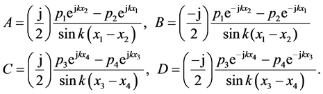
The four microphones measure the sound pressures at four indicated locations as follows
 (3)
(3)
from which the four amplitudes can be uniquely calculated in terms of the four pressures, the wave number, and the geometric positioning of the microphones and the sample [5] . In order to calculate the TL, one has to determine the four interrelated parameters of the coefficients matrix in Equation (1), known as four-pole parameters [4] . To do so, two different techniques can be applied.
In the first method (namely two-load method), each sample is tested in two different tube termination conditions: closed by a rigid cap and left open (no cap). This will provide us with four equations in four unknowns which can be solved using the Kramer method. The transmission loss factor in this case is found to be
 (4)
(4)
The subscripts h and o here, denote the rigid cap and no cap, respectively. In the second method (i.e., the anechoic termination method), the backward-travelling wave D is cancelled by means of an anechoic termination at the tube end. This way the equations, in Equation (1), are decoupled and the transmission loss factor is easily found to be equal to the ratio of A to C.
The experimental results were obtained using the testing apparatus constructed for the TL measurements at Noise, Vibration and Acoustics (NVA) Research Center of the University of Tehran. Herein, both the two-load and anechoic termination methods have been carried out for each sample. A 10 cm rolled piece of glass wool is used at the tube termination for the open-cap tube-end condition. As for the cap-closed termination, no absorbent
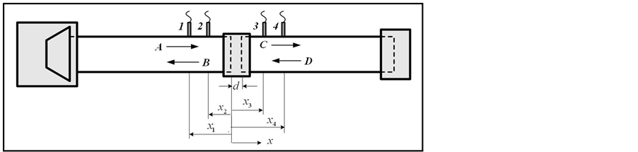
Figure 1. Schematic view of the four-microphone standing-wave tube.
is used so as to keep the two downstream boundary conditions of the tube more dissimilar. The fluid specimens were made of a Pyrex glass cylinder tube with 15 and 30 mm lengths, outer diameter 38 mm and 1.5 mm wall thickness (see Figure 2), filled with water, oil, and the nano-ferrofluid (NMF).
3. Results and Discussion
The experimental TL values of several specimens are shown below in 1/3 Octave bands (630 Hz - 4 kHz) for different gaps (or fluid space) and various methods (i.e. two-load and anechoic termination methods), see Figures 3-6. According to the Figures, the use of a liquid as middle layer increases TL over the entire frequency range. At low frequencies, where the performance of middle air layer is poor, the liquid layer provides desirable performance. Fluid density affects the TL values more than other parameters (the wave velocity and the kinematic viscosity). Hence the TL s of the cylinder tube including water, oil, and nano-ferrofluid are close to each other. The application of the liquid layer increases the resonance frequencies and shifts them to higher frequencies, which might be an advantage.
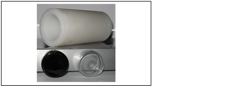
Figure 2. Sample holder (top) and test specimens (bottom: from left to right: NMF and air-filled Pyrex tube).
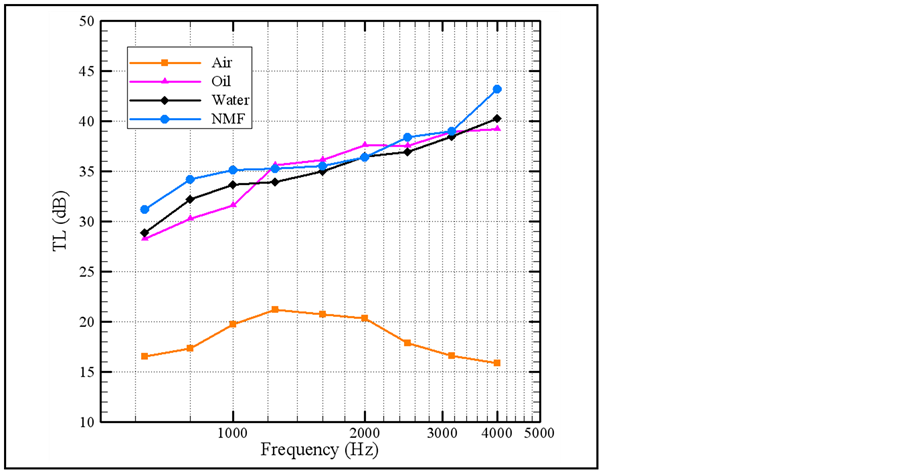
Figure 3. Experimental TL values measured for a cylinder consisting of two glass walls (1.5 mm) with middle layers of air, oil, water and NMF (d = 15 mm); two-load method.
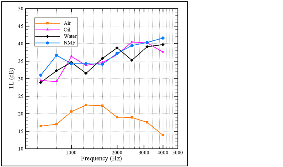
Figure 4. Experimental TL values measured for a cylinder consisting of two glass walls (1.5 mm) with middle layers of air, oil, water and NMF (d = 15 mm); anechoic termination method.
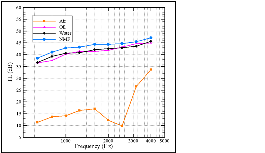
Figure 5. Experimental TL values measured for a double-layered panel consisting of two glass walls (1.5 mm) with middle layers of air, oil, water and NMF (d = 30 mm); two-load method.
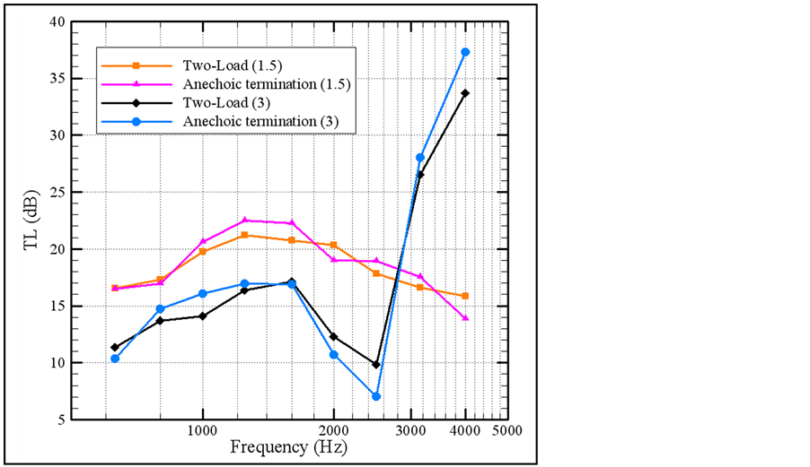
In Figures 7-10, a comparison is made between the two-load method and the anechoic termination method. The results of both methods are close. However, the two-load method leads to smoother curve or less variation of TL values for a wide range of frequencies.
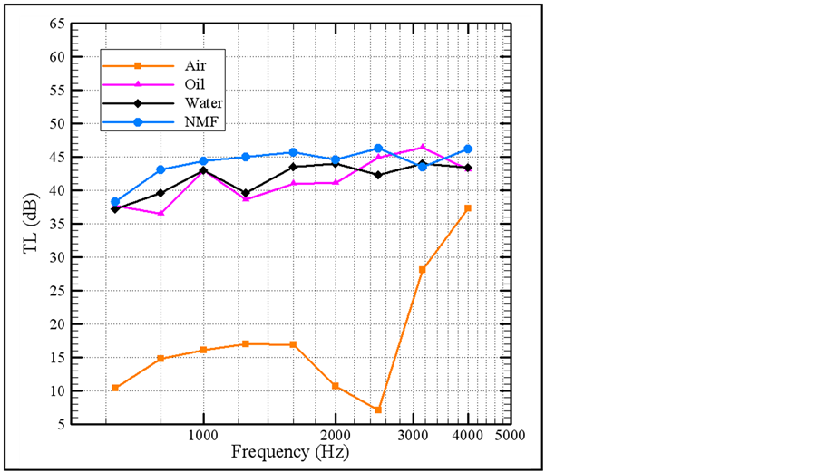
Figure 6. Experimental TL values measured for a cylinder consisting of two glass walls (1.5 mm) with middle layers of air, oil, water and NMF (d = 30 mm); anechoic termination method.
4. Conclusions
Acoustic performance of a glass cylinder containing air, oil, water and a ferromagnetic nanoparticles fluid (NMF) was evaluated experimentally. Two measurement methods were examined here, namely two-Load and anechoic
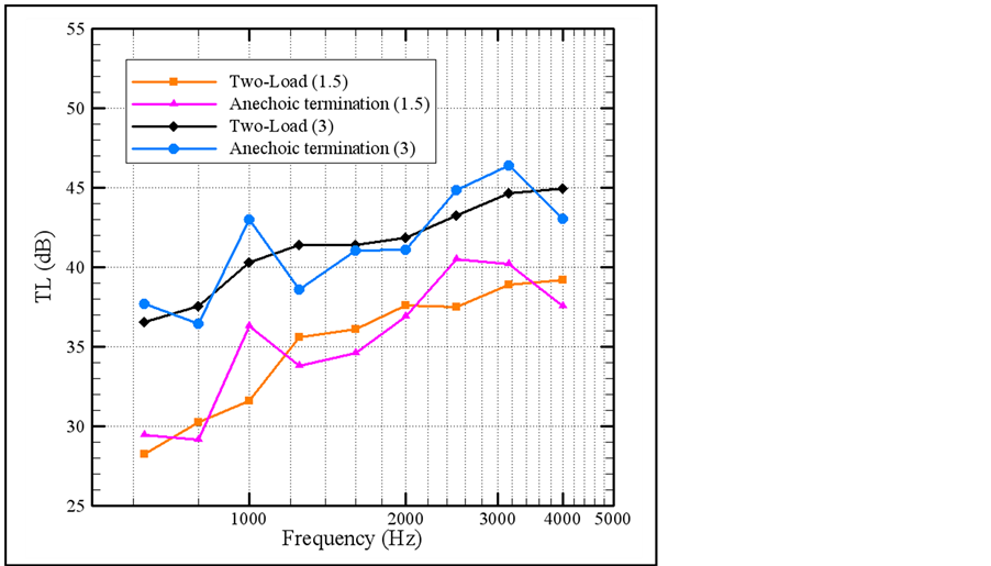
Figure 8. Experimental TL values for a cylinder consisting of two glass walls (1.5 mm) with the middle layer of air (d = 15 mm and 30 mm): Comparison between the two-load method and anechoic termination method.
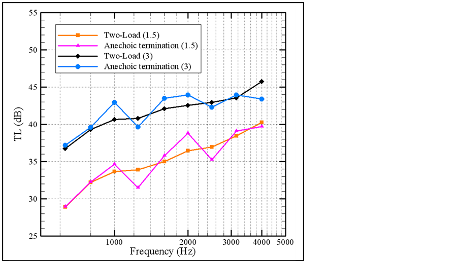
Figure 9. Experimental TL values for a cylinder consisting of two glass walls (1.5 mm) with the middle layer of air (d = 15 mm and 30 mm): Comparison between the two-load method and anechoic termination method.
termination, with different boundary conditions at the tube termination. The work was conducted for various gaps between sidewalls. The addition of liquid middle layer led to the considerable increase of the TL. Also the elimination of low resonance frequencies was noticed and they virtually moved to much higher frequencies. Fluid density form was an influential parameter in determining the TL values. In fact, acoustic panels with different fluids
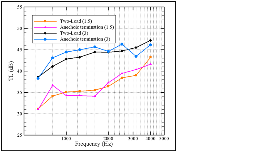
Figure 10. Experimental TL values for a cylinder consisting of two glass walls (1.5 mm) with the middle layer of NMF (d = 15 mm and 30 mm): Comparison between the two-load method and anechoic termination method.
of similar densities result in a similar performance. Increasing the middle gap led to an increase of the TL values and a decrease in resonance frequencies. For example, in Figure 3 (d = 15 mm), the resonance frequency of the air fluid is more than 5000 Hz and in Figure 5 (d = 30 mm), the resonance frequency is between 2000 Hz and 3000 Hz.
The results of both methods are close. However, the two-load method leads to smoother variation of TL values for a wide range of frequencies.
References
- Beranek, L.L. and Work, G.A. (1949) Sound Transmission through Multiple Structures Containing Blankets. The Acoustical Society of America, 21, 419-428. http://dx.doi.org/10.1121/1.1906530
- London, A. (1950) Transmission of Reverberant Sound through Double Walls. The Acoustical Society of America, 22, 270-279. http://dx.doi.org/10.1121/1.1906601
- Mulholland, K.A., Price, A.J. and Parbrook, H.D. (1968) Transmission Loss of Multiple Panels in a Random Incidence Field. The Acoustical Society of America, 43, 1432-1435. http://dx.doi.org/10.1121/1.1911003
- Munjal, M.L. and Doige, A.G. (1990) Theory of a Two Source-Location Method for Direct Experimental Evaluation of the Four-Pole Parameters of an Aerospace Element. Journal of Sound and Vibration, 141, 323-333. http://dx.doi.org/10.1016/0022-460X(90)90843-O
- Song, B.H. and Bolton, J.S. (2000) A Transfer-Matrix Approach for Estimating the Characteristic Impedance and Wave Numbers of Limp and Rigid Porous Materials. The Acoustical Society of America, 107, 1131-1152. http://dx.doi.org/10.1121/1.428404