Open Journal of Safety Science and Technology
Vol.3 No.3(2013), Article ID:37087,8 pages DOI:10.4236/ojsst.2013.33006
Numerical Evaluation of Symmetric Prism Method to Analyze the Splitting Forces Due to TBM Jack Loads
1 Civil Engineering Department, Eyvanekey Institute of Higher Education, Semnan, Iran
2Civil Engineering Department, Semnan University, Semnan, Iran
3Civil Engineering Department, Islamic Azad University, Fars Science and Research Branch, Shiraz, Iran
Email: Saberi.hamid@gmail.com
Copyright © 2013 Hamid. Saberi et al. This is an open access article distributed under the Creative Commons Attribution License, which permits unrestricted use, distribution, and reproduction in any medium, provided the original work is properly cited.
Received December 7, 2012; revised January 6, 2013; accepted January 20, 2013
Keywords: Tunnel; Concrete Segment; TBM Jack Loads; Symmetric Prism Method; Numerical Solutions
ABSTRACT
Final lining in mechanized excavation includes the precast concrete segments. These segments are designed for applied loads during construction, moving, depot, assembling in the tunnel and service loads that are affected by earth conditions. One of these loads that are applied to the segments after assembling in the ring, are TBM jack loads especially when the TBM should excavate squeeze zones with single mode. As the jack pad section is smaller than the segment section, it causes splitting loads in the segment. Symmetric prism method is an approximate solution to evaluate these forces. In this paper, calculated results by this method are compared to that of numerical solution by ANSYS software. It shows 10 - 20 percent difference between numerical and analytical results.
1. Introduction
Final lining in mechanized excavation includes the precast concrete segments. After the excavation, these linings will be installed within shield by Tunnel boring machine (TBM). TBM auxiliary jacks aimed to function after each excavation cycle to install precast segmental linings, moving back part and pulling TBM back up [1]. The carrying loads of each jacks to move forward the TBM at the normal mode is estimated 50 tons at water tunnels having conventional excavation diameters equal to 4.5 meters which will be applied by jack thrust to precast lining thickness along tunnel. Though, considerable compressive loads are required to move the TBM at the critical cases which estimated 1550 tons for TBM jacks. These loads are contributed within ten cylinders and are applied to segments by pads. Therefore, the applied loads from each jacks to segments amounted to 155 tons which are considered to evaluate such linings. Whereas, the cross section of the jack is smaller than precast segmental lining thickness, the transverse tensile loads will be developed due to splitting moments by jack pressure. Symmetric prism method is one of the approximate methods to calculate such loads. This paper is aimed to analyze the accuracy of this method with three dimensional modeling of segments by FEM software, ANSYS. Figure 1 shows the application point of jack loads on final lining of typical tunnel having excavation diameter equals to 4.5 meters.
2. Analytical Evaluation of Applied Loads on Precast Segments Due to TBM Jack Loads Using Symmetric Prism Method
Since the plane sections are not remained plane exactly beyond the concentrated load, the Euler-Bernoulli beam theory cannot be applicable. Contours of compressive stress on beam due to concentrated loads are shown at Figure 2. The stress contours are directly beyond concentrated loads related to centerline of convex member and act perpendicular to member axis due to transverse component of compressive stress. The contours of compressive stress at farther distance of restrained part are concave related to member axis which causes transverse tensile stress components. The contours of stress are close together exactly beyond the load application plane and also the compressive stress is high. The distance of stress contours will be increased due to an increase in distance of restrained planes. The length of this area for concentrated load is suggested to consider approximately equal to depth of the member, D, in accordance with Saint-Venant’s principle. The variation of transverse stresses along the
 (a)
(a) (b)
(b) (c)
(c)
Figure 1. Application point of TBM jack loads on final lining and typical tunnel section.
 (a)
(a) (b)
(b)
Figure 2. Contour lines of stresses for concentrated loads applied over the plane [2]. (a) End elevation; (b) Side elevation.
centerline of the member and perpendicular to that are shown at Figure 3. The amount of curvature contours depends on the size of the load application plane. The curvature and stress concentration contours will be higher if the load application plane is smaller; therefore, the transverse tensile and compressive loads at close area to concentrated load application point will be higher. Generally, such transverse tensile loads cause splitting loads at concrete and transverse reinforcements are required at these areas [2].
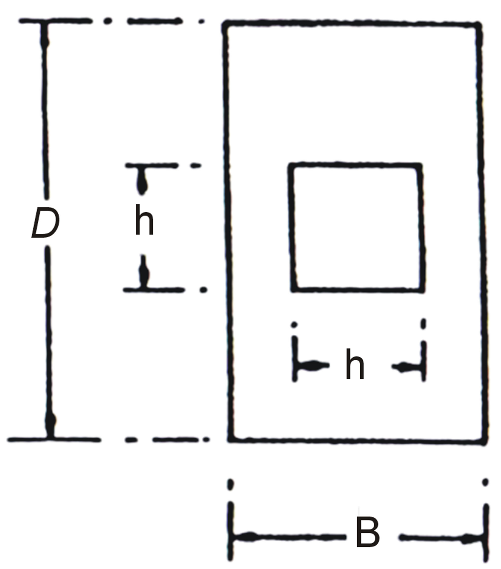
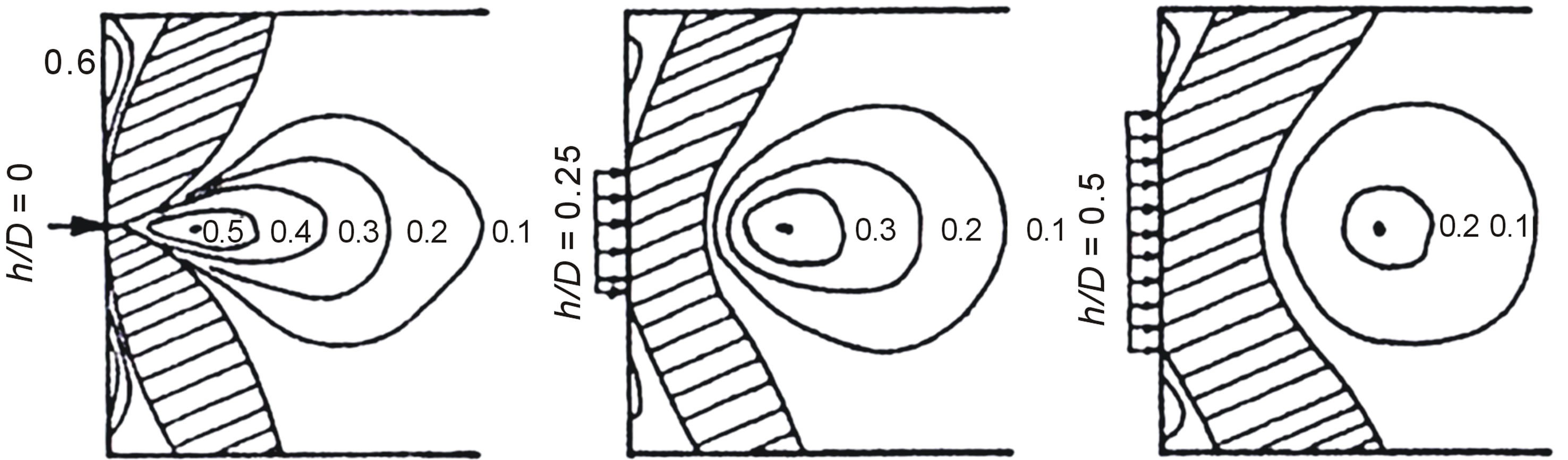
Figure 4 shows the stress isoloads  due to central concentrated loads having different dimensions of load application plane. These stress distributions are obtained using Finite element and Photoelastic method. The influence of variation at load application plane dimensions on value and position of transverse stress can be observed at Figure 4. The maximum transverse tensile stress at member axis will be decreased and the distance to load application plane along the member will be increased if the size of the plane increases. Also, the tensile stresses are at the adjacent edges of restrained plane. Despite the fact that such stresses are rather high, act quantitatively on surface where the ultimate tensile load is low. The contours of stress at typical prismatic member having multiple concentrated loads are shown in Figure 5.
Totally, the applied load is distributed along the depth and width of the restrained area where transverse reinforcements are required at each perpendicular ends (vertically and horizontally at sections of restrained areas). The required reinforcements at each direction are obtained by two dimensional analysis where vertical and horizontal transverse tensile loads are calculated and obtained by vertical and horizontal load distribution, respectively. The truss model is one of the simple models to analyze such sections. The truss action is considered at this simple model which has been shown in Figure 6. The analog truss shows that transverse pressure is exactly beyond the plane and the transverse tensile load which is often known as splitting load is observed along typical distance of the member. Whereas, the splitting is developed due to maximum bearing moment, usually is represented by Mb and is known as splitting moment. Considering the half of the end block as the free body diagram, the splitting moment is obtained from static equations.

Figure 3. Distribution of transverse stresses beyond concentrated load [2].
 (a)
(a)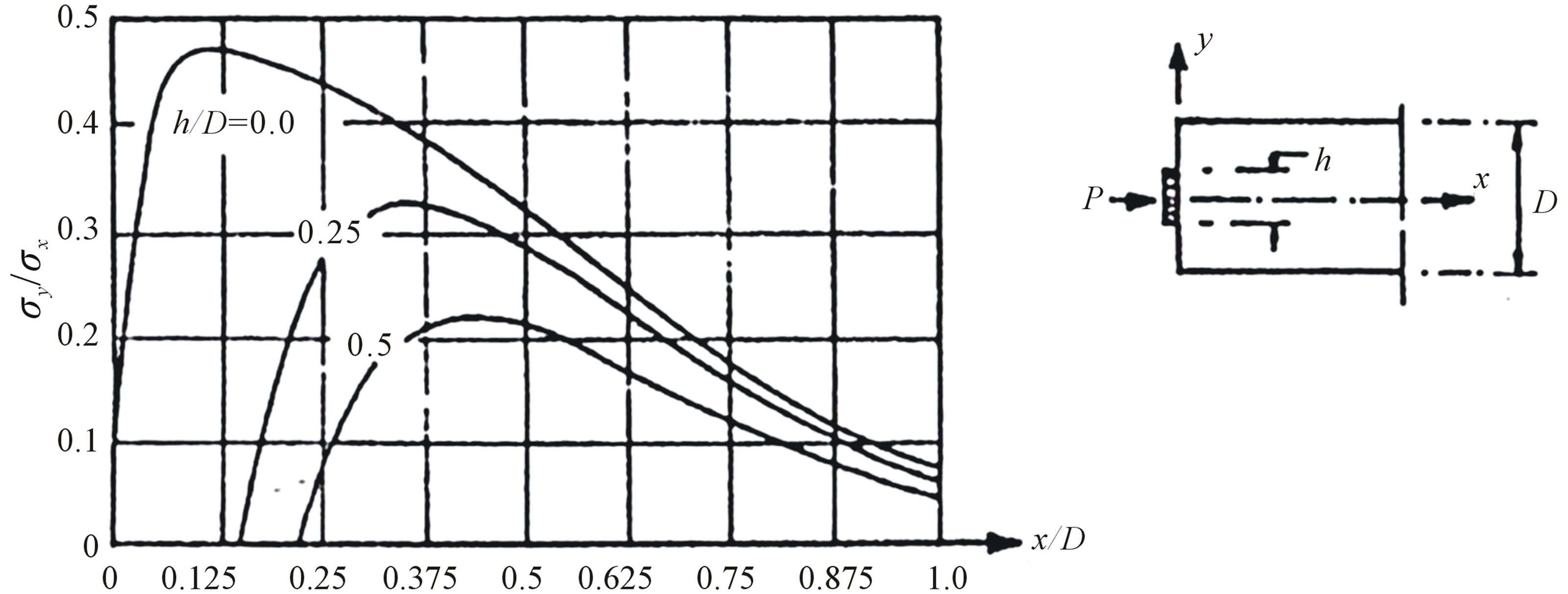 (b)
(b)
Figure 4. Distribution of transverse stresses for symmetric (central) concentrated loads [2]. (a) Stress Isobars ( ); (b) Transverse stress along member axis for various anchorage plate sizes.

Figure 5. Transverse stress isoloads for multiple concentrated loads [2].
Figure 6. Analog truss for one and two concentrated loads [2].
 (1)
(1)
The resulting vertical tensile load, Tb, is located at a distance from load application plane at curve centroid of transverse tensile stress, according to Figure 3. For the central concentrated load which has been shown, the moment arm between Cb and Tb is approximately equal to D/2. It seems that this estimation can be used for cracked concrete area. Where,
 (2)
(2)
The approximate method of symmetric prism can be used for multiple concentrated loads. The depth of symmetric prism (De) for a concentrated load can be considered the smallest distance along the transverse tension from restrained center to the closest adjacent restrained center and two times of the distance along transverse tension from restrained center to the closest edge of the restrained area. It can be observed that tensile load due to over-break moment (Ms) at edges of the beam can be developed as well as tensile loads due to splitting moments (Mb) while concentrated load and also concentrated load out of the axis exist. Where, maximum overbreak moment and internal tensile load due to moments can be obtained from following equations.
 (3)
(3)
 (4)
(4)
According to this method, the reinforcements are applied vertically and horizontally and the transverse reinforcements which are calculated thereof shall be placed through all parts of the restrained area that is vulnerable to cracking. Therefore, the steel cross section Asb shall be uniformly distributed at the distance of 0.2 De to De from end area of the loading.
Where, the concentrated load is applied at a small surface of the beam section, the tensile loads along horizontal and vertical directions are developed. Closed stirrups are used to meet the horizontal and vertical reinforcements which are extended to a distance of the smaller dimension of the beam. Figure 7 shows schematic section reinforcement for two symmetric concentrated loads.
Based on analog truss of the segment, the jack loads along longitudinal direction and also segment thickness are distributed as compressive stress. The tensile loads along longitudinal direction of the segment and segment thickness are carried by longitudinal reinforcements and reinforcements along segment thickness, respectively.
The transverse tensile load will be considered and

Figure 7. Typical details of reinforcements for two symmetric concentrated loads on beam [2].
calculated along longitudinal and radial direction for the segment. Using symmetric prism method, the transverse tensile load for multiple concentrated loads is obtained as follows.
 (5)
(5)
where, Fp: the maximum load of each jack, Lpi: the width of the pad under the jack, Le: effective length of the segment or the depth of the symmetric prism. The depth of the symmetric prism for calculating the transverse tensile load along longitudinal direction of the segment is equal to the smallest distance of two concentrated loads of the jacks (106 cm) and two times of the distance of influence point of concentrated load of the jack to the closest edge of the concentrated load application area (114 cm). Thus, the value of Le is considered 106 cm.

The depth of the symmetric prism is considered equal to segment thickness (30 cm) to calculate the transverse tensile load along radial direction of the segment.
On the other hand, as it was described for stress distribution due to two concentrated loads, the tensile load due to over-break moment is developed at edge of the segment and between two concentrated compressive loads.
where,
3. Numerical Evaluation of Applied Loads on Segments Due to TBM Jack Loads Using Finite Element Model
The full scale segment is modeled by ANSYS software to control the symmetric prism equations to design reinforcements of segment under jack loads during TBM advance (Figure 1). The dimensions of jack pads are also considered 43 × 16 cm at jack locations (Figure 8).
3.1. Properties of the Materials, Meshing and Load Application Trend
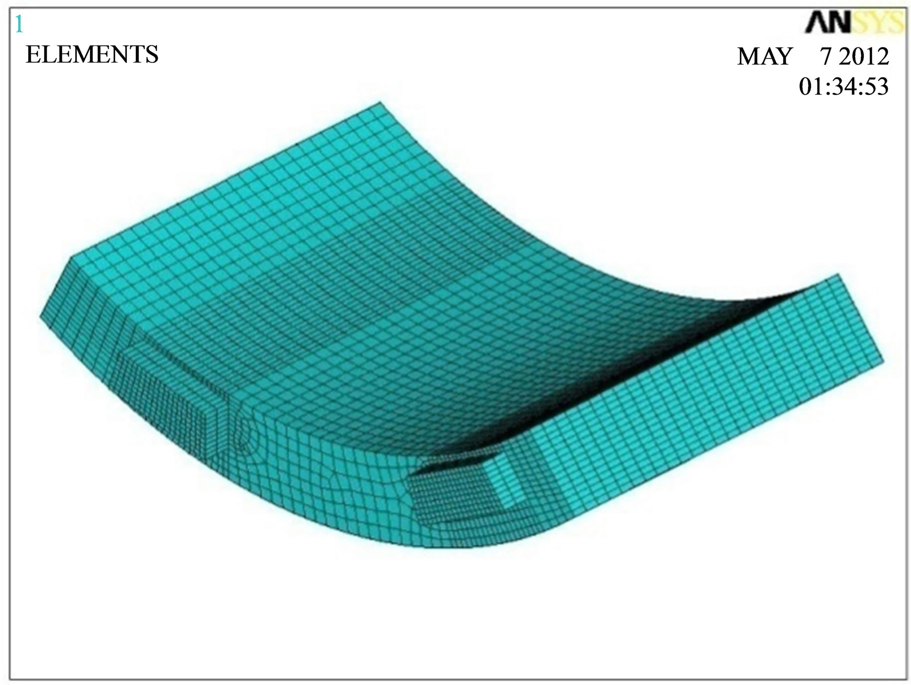
Concrete having compressive strength of 40 MPa, tensile strength of 4 MPa and modulus of elasticity equal to 30.2 GPa is used. The reinforcements having yield tensile strength of 400 MPa is modeled. Three dimensional elements, SOLID65 and SOLID45 have been used to mesh and model concrete and pad, respectively [3] (Figure 9). The jacks have been considered steel materials to uniformly transfer the loads. The reinforcements have been considered volumetric having ratio of 0.004, 0.0028 and 0.0055 for longitudinal, transverse and ladder reinforcements, respectively. Figure 10 shows the meshing of the segment structure.
According to Figure 10, the end nodes of the segments have been restrained to meet the support condition considering the arrangements of segments within the ring and supporting to previous ring during load application of the jacks while TBM advances.
The loading gradual trend within 31 steps has been written by APDL commands to approach to each jack thrust having 155 tons and apply to the model.
3.2. Analysis Results
The Von Mises stress at the end of the loading at Step 31 is shown in Figure 11. The stress distribution at three sections of the segments has been evaluated and the resulted loads have been calculated and compared with
Figure 8. Geometrical model of the segment in software.
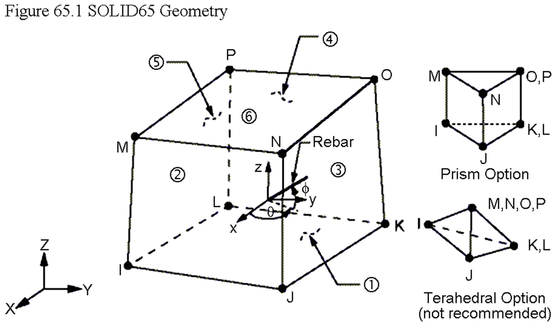
Figure 9. SOLID65 element [3].
symmetric prism pattern to consider the transverse tensile loads (splitting loads) along longitudinal direction (Tb1), radial direction of the segment (Tb2) and also tensile loads due to over-break moment between two jacks (Ts), (Figure 12).
3.2.1. Calculating the Transverse Tensile Loads (Tb2) Along Longitudinal Direction of the Segment (Section A-A)
According to analytical calculations, this load is equal to 23 tons in accordance with symmetric prism pattern that longitudinal reinforcements are controlled within transverse range 0.2Le-Le (i.e. 20 - 96 cm) to carry the load. Stress distribution (SX) at section A-A has been used to calculate this load within this surface (Figure 13). Maximum stress times the equivalent surface is conservatively equal to load value.
where,

3.2.2. Calculating the Tensile Load Due to Over-Break Moment between Two Jacks (TS) (Section B-B)
According to analytical calculations, this load is equal to
 (a)
(a)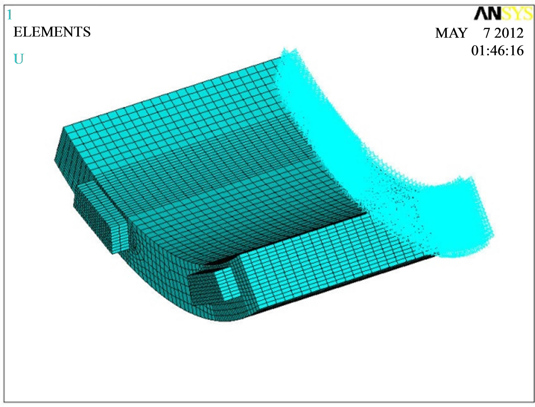 (b)
(b)
Figure 10. Finite element mesh of the segment and support conditions.
9.5 tons in accordance with symmetric prism pattern that longitudinal reinforcements are controlled within transverse range 0 - 0.2Le (i.e. 0 - 20 cm) to carry the load. Stress distribution (SX) at section B-B has been used to calculate this load within this surface (Figure 14). Mean stress times the equivalent surface is equal to load value.
where,

3.2.3. Calculating the Transverse Tensile Load (Tb1) Along Radial Direction of the Segment (Section C-C)
According to analytical calculations, this load is equal to 18 tons in accordance with symmetric prism pattern that ladder reinforcements are controlled within transverse range 0.2Le-Le (i.e. 6 - 30 cm against jack pad having the width of 45 cm) to carry the load. Stress distribution (SY) at section C-C has been used to calculate this load within this surface (Figure 15). Maximum stress times the equivalent surface is conservatively equal to load value.
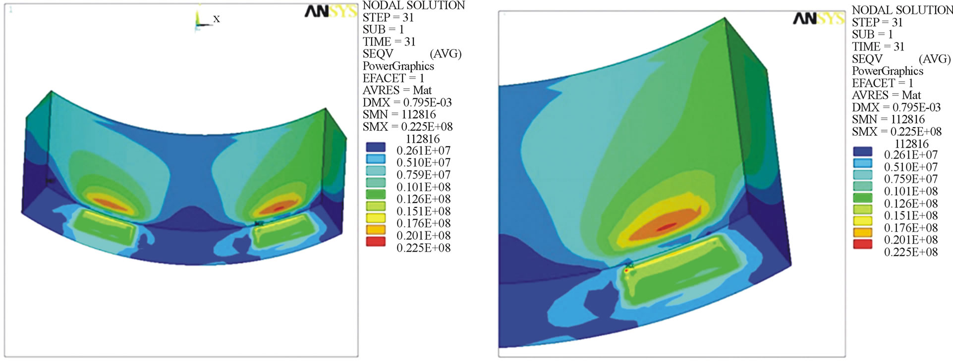
Figure 11. Von Mises stress of segment at the end of the loading (Pa).

Figure 12. Sections for calculating the loads.

Figure 13. Stress SX at section A-A (Pa).
where,

4. Conclusion
One of these loads that are applied to the segments after assembling in the ring, are TBM jack loads especially

Figure 14. Stress SX at section B-B (Pa).

Figure 15. Stress SY at section C-C (Pa).
when the TBM should excavate squeeze zones with single mode. As the jack pad section is smaller than the segment section, it causes splitting loads in the segment. An approximate solution to evaluate these forces is used of the symmetric prism method. In this paper, calculated results by this method are compared to that of numerical solution by ANSYS software. It shows 10 - 20 percent difference between numerical and analytical results.
5. Acknowledgements
The authors would like to thank the Dr. Mohsen Gerami for his kind help.
REFERENCES
- V. Guglielmetti, A. Mahtab and S. Xu, “Mechanized Tunneling in Urban Areas,” Taylor & Francis, Balkema, 2008.
- P. W. Abeles and B. K. Bardhan-Roy, “Prestressed Concrete Designer’s Handbook,” 1981.
- ANSYS User Manual 2005 ANSYS, Inc.