Open Journal of Stomatology
Vol.06 No.01(2016), Article ID:62852,10 pages
10.4236/ojst.2016.61002
A new Volumetric Parameter for a Comparative Finite-Element analysis of a Six- or four-Implant mandibular total-Arch rehabilitation
Alfredo Natali1*, Enrico Bertocchi2, Andrea Baldini2, Giuseppe Antonio Mulas3, Matteo Martinolli4, Bortolini Sergio5
1DDS, Teacher at the PhD “Enzo Ferrari” in Industrial and Environmental Engineering, University of Modena and Reggio Emilia, Modena, Italy
2Department of Engineering “Enzo Ferrari”, University of Modena and Reggio Emilia, Modena, Italy
3Tecnopolo di Mirandola, Science and Technology Park for Medicine, Mirandola, Italy
4School of High Mechanics and Automotive Design & Technology, Department of Mechanical and Civil Engineering University of Modena and Reggio Emilia, Modena, Italy
5Department of Surgery, Medicine, Dentistry and Morphologic Science with Interests in Transplant, Oncologic and Regenerative Medicine, University of Modena and Reggio Emilia, Modena, Italy

Copyright © 2016 by authors and Scientific Research Publishing Inc.
This work is licensed under the Creative Commons Attribution International License (CC BY).
http://creativecommons.org/licenses/by/4.0/


Received 18 October 2015; accepted 16 January 2016; published 19 January 2016
ABSTRACT
In a full-arch implant rehabilitation ad modum Branemark, the distribution of stress and strain in mandibular bone is influenced by the type, number and position of implants used. In particular, the biomechanical behaviour of the bone structure after complete osseointegration depends on the load transferred to the bone by each fixture. In this study, a finite-element analysis of two models was performed. Models of an all-on-four configuration and a six-implant configuration were compared in a worst-case scenario. A new V parameter is presented to aid the quantitative and comparative analysis of the all-on-four and six-implant configurations. The influence of orthotropy was also investigated, and a geometric change in the all-on-four configuration is presented.
Keywords:
Finite-Element Analysis, oral Implants, all-on-four Configuration, Six-implantconfiguration, Bone mechanics, Comparative Analysis

1. Introduction
Dental implants are a fundamental surgical treatment to restore dentition. One of the worst failure modes of this treatment is ascribable to bone loosening around the implant due to un-physiological stress response under masticatory load. Because of the current impossibility of direct measurement or analytical treatment of the problem, FEM analysis was used to simulate the behaviour of bone and implants under this stimulus [1] -[3] . In mathematics, the finite element method (FEM) is a numerical technique for finding approximate solutions to boundary value problems for partial differential equations. It uses subdivision of a whole problem domain into simpler parts, called finite elements, and variational methods from the calculus of variations to solve the problem by minimizing an associated error function. Over the last 10 years, many studies have investigated, for example, the influence of the number and inclination of implants in dental replacements [2] [4] [5] . In spite of the number of studies the best number of implants or a universal parameter to assess the stress affecting the bone is still under analysis. The former is rarely discussed in literature [6] , while the latter is more widely covered, with numerous papers considering equivalent von Mises stress (EvMS) as a safe of bone stress parameter [1] [3] [5] -[9] , but others [10] considering the EvMS unreliable. An alternative stress index, the elastic strain energy density, is extensively used as a key bone remodelling factor in related literature, see for example references [11] -[13] . The use of EvMS is often related to a rather simplistic assumption of isotropic, homogeneous bone scheme [1] [3] [5] -[9] . This type of assumption is helpful in the face of the growing complexity of mechanical property characterization. EvMS is also specifically defined in order to ignore the hydrostatic stress tensor component, which is known to be insignificant for wide families of materials, although no specific verification is available for bone.
On the basis of a new parameter, the present study develops a finite element model to analyse the mechanical behaviour of two mandibular full arch titanium bridges mounted on four and six Sweden & Martina implants (4.10 mm in diameter and 15 mm in length) respectively. The aim of this study is both to introduce a new scalar parameter summarizing the peri-implant bone stress condition, and compare the six-implants and all-on-four configurations for supporting a complete mandibular dental bridge.
2. Materials and Methods
The mandible model was created by converting computed tomography (CT; Aquilon™ 16; Toshiba Medical Systems Corporation, Otawara-shi, Japan) images into a three-dimensional (3D) finite element model (FEM) using the Altair HyperMesh™ (9.0; Tokyo, Japan) software. The model was then imported in MSC Marc™ (2007r1; Santa Ana, CA, USA) software for finite-element analysis. A CT scan yielded only a partial model of the mandible which did not include the zones near the condyle (Figure 1). These zones are considered in kinematics even if not in compliance, however the influence of the latter is small it being remote from the stress sampled areas, and with the support system quasi-isostatic. Implant components used in the simulation were Out-Link2™- Sweden & Martina™, Due Carre (PD), Italy. The full-arch bridge was modelled as a curved, inverted T-beam section passing 4 mm above each implant. Since the implant location is anatomically defined, the bridge shape is complex. The connection between the abutment and dental bridge was simulated as a hollow circular beam, with inner and outer diameters of 2 and 2.46 mm respectively. The materials’ mechanical properties were taken from bibliography (Table 1) [9] [14] -[16] . In particular, cortical bone was considered orthotropic, whereas both trabecular bone and titanium were modelled as isotropic. Moreover, to investigate the influence of orthotropy itself, a second FEM simulation was run, in which the cortical bone was modelled as isotropic, with properties as in Table 1. This check is relevant because, although CT data permits the analyst to achieve a reliable geometrical representation of the mandible, to the best knowledge of the authors, it is not possible to obtain a pointwise assessment of the orthotropy of the principal directions vector field, and some degree of arbitrariness is inevitable. In the present model the orthotropic material principal directions are oriented according to on a sliding cylindrical coordinate system, the axis of which is locally tangential to the mandible bone curve centreline. The first material preferential direction (direction 1) was thus assumed to be locally axial to the mandible structure, the weakest direction (direction 3) was considered as radial and hence roughly normal to the cortical layer, and the second preferential (direction 2) was derived as orthogonal to the other two. As regards the remodelled bone areas (a 0.8 mm thickness around each implant), a fully isotropic bone model was used. Such variations in material properties are known in literature, see references [17] and [18] , and moreover the authors were fully aware that a global orientation procedure was locally unreliable due to the alteration of the beam-like structure induced by dental cavities.
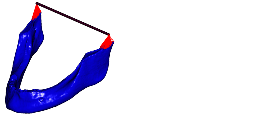
Figure 1. Model of the mandible used in the finite-element analysis. The red links indicate a rigid connection between the condyle zone and the cylindrical joint displayed.

Table 1. Mechanical characteristics of the materials employed.
The finite element model of the bone contains 296 k nodes and 1.34 mln linear tetrahedral elements; most of those elements (725 k) are located within the cortical bone structure. The average element size of 0.6 mm edge length on the cortical bone enables the presence of at least two elements across the layer thickness.
To simulate muscular loads, a control node was created and linked to the nodes located near the insertion zones identified as (1). A force was applied to the control node in the physiological direction of the muscle. The internal and external masseter, medial and internal pterygoid, and temporalis muscles were considered in this model; the lateral pterygoid muscle was not included. The muscular force values were taken from literature (1): the muscular load application areas are shown in Figure 2, and the directional cosines of the loads are listed in Table 2. Moreover the numerical values of the muscular loads are scaled in respect to (1) in order to yield an occlusal force of about 400 N, as in [19] . The kinematics of the mandible was modelled with two cylindrical joints at the condyle areas as shown in Figure 1. In analogy with physiological behaviour, the rotation of the structure was constrained by a contact support in dental bridge which reacts to the jaw closing force. The corner of the bridge (Figure 3(a)) was chosen to simulate the worst-case loading scenario [6] . The bone-fixture interface was modelled as a fully adherent interface between the two elastic bodies. Full displacement continuity was granted across the interface; the normal stress component and tangential shear actions were also continuous. This behaviour marches a complete osseointegration. The fixture-abutment interface was also analogously modelled in order to simulate a regularly tightened threaded connection.
Two independent models were created on the basis of the aforementioned boundary conditions. The first one with six implants as shown in Figure 3(a), with the two distal implants inclined at 30˚ approximately. The second implemented an all-on-four configuration as in Figure 3(b), with implants 2 and 5 removed. The remaining four implants were in the same position in both models. It is important to note that the positions of the implants were based on an actual clinical case.
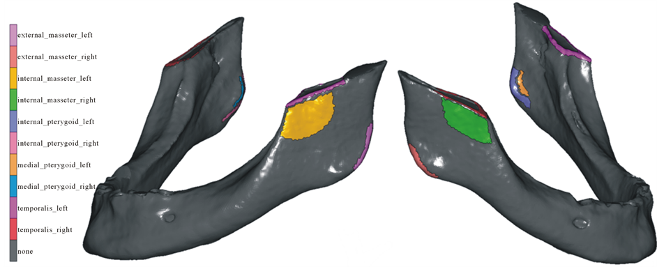
Figure 2. Zones of muscular load application [1] .
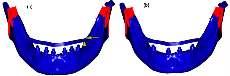
Figure 3. Model of the six-implant (a) and all-on-four (b) configuration . In the six-implant image the yellow arrows indicate the fixed displacements of the dental bridge. In both models the red links indicate the muscular loads.
Table 2. Directorial cosines and intensity of the muscular loads used in the simulations [1] .
The V parameter
The MSC™ Marc/Mentat 2007r1 Finite Element solver, pre and post-processor suit was used. Firstly, the resultant force and moment acting on all the fixtures along the dental bridge were retrieved for both the configurations. Then, the resultant force and moment of the most loaded fixture were analysed in term of their components along three orthogonal axes based on the Gram-Schmidt orthogonalization of the following directions: the axis of the fixture (a), the local longitudinal axis of the bridge (l), the third transverse axis (t) derived as normal to the previous two. However, the lack in literature of a consolidated, experimentally validated equivalence formula for complete (Nl, Na, Nt, Mfl, Mt, Mft) and purely axial loads prevents a direct (scalar) comparison between the load levels at the implants, and further parameters (stress level based) have to be considered. The equivalent von Mises stress (EvMS) is ubiquitous in literature and in mechanical engineering practice as a pointwise stress level index, and its peak within the structure is usually taken as representative of the overall criticality. The choice of the EvMS as a multiaxial to uniaxial equivalency index for metals is preferred over others since it neglects the hydrostatic stress component, which is known not to cause damage in such materials; unfortunately, since the same information is not available within the bone realm, a more proper choice is perhaps the Equivalent Beltrami Stress (EBS), since it takes into account both the deviatoric and hydrostatic stress components. Such a choice is analogous to the adoption in literature of the strain energy density (SED) as a stress level indicator, with the relation

between the two quantities in the isotropic realm (E being the material Young modulus). Moreover, the stress field is known to be singular (i.e. unbounded) at multi-material interfaces under given conditions―see e.g. [20] [21] . In particular, at the first-adherence edge between an implant and the surrounding bone tissues, a singular field is predicted; in the example configuration of a 90˚ angle profile of the bone component (Figure 4), the local stress spike has unbounded components

according to [22] formulas. The discrete nature of the FEM method forces the resultant stress levels―and consequently both EBS and EvMS―to remain finite, but its pointwise value at the material discontinuity edge is a function of the local element shape and size, and predicted to indefinitely grow as the latter decreases. An appreciably blunt edge profile in the FE model would be required to regain stress peak significance. To overcome the singular peak issue, the authors introduced a volumetric based parameter V, defined as the volume of bone [mm3] exceeding a certain EBS value (or equivalently a certain strain energy density value). A deeper analysis of this choice is presented in paragraph 4. The upper limit of the EBS value from literature was designated as the cortical tensile strength value reported in [11] , i.e. 120 MPa. Although this value is relatively high, it was chosen because the analysis considers a worst-case scenario in terms of loads. In any case, such a choice is not critical since the analysis must be intended as comparative, rather than absolute. An increase in the V parameter indicates an increase in the quantity of bone stressed above the damage threshold, and hence a more critical condition for the structure. In the perspective of a remodelled prone material, such an index appeared preferable to the authors compared to the peak stress value, since it could better represent the adaptation efforts of living tissue in load bearing situations.
To evaluate the influence of orthotropy on the models, the same analysis was repeated with the assumption of cortical bone isotropy. The mechanical properties of cortical isotropic bone are listed in Table 1. Moreover, a bridge cantilever length variation was introduced in the configuration with the greatest V parameter value; the amount of geometrical correction was then tuned in order to achieve matching criticality indexes. The interest in the influence of such adjustment is related to the fact that this empirical correction is customary in the dental surgery practice.
3. Results
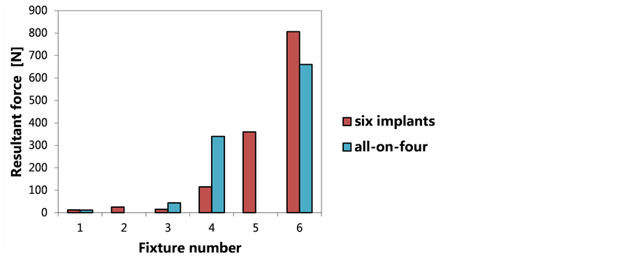
Numerical values for the resultant force and moment magnitude acting along the dental bridge are shown in Figure 5. In both the all-on-four and six-implant configurations, the most loaded implant was fixture No. 6. The force and moment components acting on fixture No. 6 in both configurations are reported in Table 3, which also shows the relative variance. The V values for both the models are collected in Table 4. In the model with the
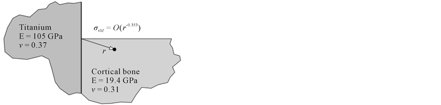
Figure 4. Plane strain local modelling.
 (a)
(a)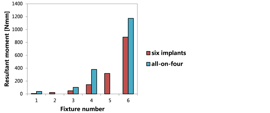 (b)
(b)
Figure 5. State of equivalent force (a) and moment (b) along the dental bridge in the six-implant and all-on-four configura- tions. The numerical data are relative to a thin-walled section beam. In both models, implant No. 6, which was closest to the external stimulus, showed the highest loading. For this fixture, the all-on-four configuration had less equivalent force but a greater equivalent moment than the six-implant configuration.
Table 3. Numerical values and percentage change in the force and moment in the longitudinal, axial, and transverse directions in the all-on-four and six-implant models. Because the values obtained were dependent on the control node position, the node was maintained at the surface height of the mandibular bone and along the fixture axis to simulate stresses on the bone surface.
Table 4. Numerical values and percentage change in the V parameter.
six-implant configuration, stress/strain levels exceed the reference limit in a much smaller volume of bone than in the all-on-four model. Strain energy density maps are shown in Figure 6 for both the configurations.
Table 5 and Table 6 list the force and moment components split along the three orthogonal axes, the V parameter values for both the orthotropic and isotropic cases in both configurations; data relative variation is also presented. Since according to Table 4 the all-on-four configuration leads to higher V values, the cantilever length was parametrically reduced by shortening the bridge; the resulting V values for the six-implants and the all-on-four are found to be equal in the case of a 2.0 mm length correction value.
4. Discussion
The choice of the V parameter is due to the necessity to introduce a more mesh-independent criterion compared to the usual “maximum equivalent stress”. Stress singularities are predicted at bi-material interfaces in well known families of cases [3] [20] [21] . The definition of the V parameter is based on EBS, and hence on the reduction of the multiaxial stress state to a simpler uniaxial one by using an elastic deformation energy density equivalency criterion. Moreover, by using the V parameter is possible to establish stress states in terms of an equivalent volume, which seemed to the authors significantly more comprehendible and practically applicable than an energy density or EBS value. Considering the numerical simulation results, the load with highest magnitude is borne by the sixth fixture of the six-implant configuration, whilst the maximum moment in magnitude
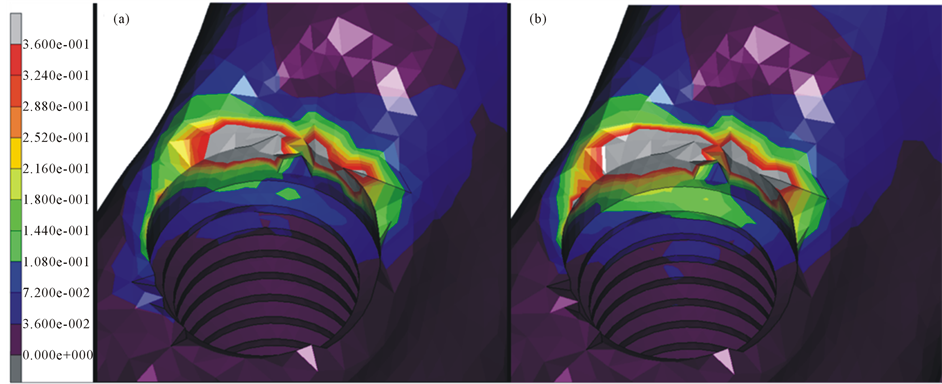
Figure 6. SED in six-implant (a) and all-on-four (b) configuration. The maximum value of 0.36 is for 120 MPa of EBS.
Table 5. Differences in force, moment, and V parameter values in the six-implant model caused by the change from ortho- tropic to isotropic cortical bone.
Table 6. Differences in force, moment, and V parameter values in the all-on-four model caused by the change from ortho- tropic to isotropic cortical bone.
acts on the same fixture in the all-on-four configuration, as shown in Figure 4. It is impossible from the aforementioned data to determine which configuration showed superior performance, it being difficult to meaningfully reduce forces and moments to a common parameter. By conducting a component specific analysis of the resultant load as in Table 3, the data show that only the axial force component is smaller in the all-on-four model, whilst all the others are significantly higher. Because this component is known to be the less critical one [23] , the previous observation suggests that the six-implant configuration performs better than the all-on-four variant. The analysis of V parameter values is coherent with such an interpretation since, as in Table 4, a greater V value was found for the all-on-four configuration for the same geometry, materials, and boundary conditions. In addition, the trend was confirmed by EBS value maps (Figure 7).
The results of the orthotropic and isotropic models were compared. As previously mentioned, such comparison is useful to estimate the influence of material anisotropy, since its characterization is error prone due to the uncertainty of a pointwise definition the principal directions. Far from being an academic exercise, the isotropically approximated bone material, with E = E3, fits both the nature of the bone in the implant proximity―which is the area of actual interest, and the global bending behaviour of the mandible, the latter being a hollow-section beam-like structure, of which the longitudinal modulus (E_1 as described above) is the only elastic modulus concurring to define the bending stiffness. In fact, as shown in Table 5 and Table 6, the two different material models return very similar results. The present analysis showed that the orthotropic/isotropic bone modelling switch for the cortical bone did not significantly influence the load born by the various implants, in accordance with [5] [7] -[9] . However, the V parameter was affected by the material modelling change, confirming that the orthotropic nature of the cortical bone is not negligible in quantitative analysis of the behaviour of dental implant. From a clinical perspective, the V parameter analysis provides data that the dental surgeon can exploit in order to appropriately modify the cantilever geometry, thereby reducing the stress conditions in the bone, and specifically to achieve with an all-on-four layout the same safety conditions as a six-implant configuration.
5. Conclusions
Analysis confirmed that an increase in the number of implants in general decreases stress levels at the bone- implant interface, although the significantly hyperstatic nature of the structure makes this type of conclusion problematical, clearly leaving space for counter examples. Furthermore, it was found that bone stress behaviour differed between orthotropic and isotropic cortical bone materials, and it was thus concluded that a modelling choice of this type influences the results. Finally, a new scalar index was introduced, the V parameter, which

Figure 7. Trend of the V parameter with variation in equivalent Beltrami stress (EBS).
provides quantitative results related to the stress condition of mandibular bone. A reduction in cantilever length was proposed in order to decrease V parameter values in all-on-four layouts and increase safety up to typical six-implant configuration levels.
Acknowledgements
The authors wish to thank Ing. Eleonora Campioni for her valuable help in writing the methods and analysing the data for this article.
Conflict of Interest
The authors received no financial support and declare no potential conflicts of interest with respect to the authorship and/or publication of this article.
Cite this paper
AlfredoNatali,EnricoBertocchi,AndreaBaldini,Giuseppe AntonioMulas,MatteoMartinolli,BortoliniSergio, (2016) A New Volumetric Parameter for a Comparative Finite-Element Analysis of a Six- or Four-Implant Mandibular Total-Arch Rehabilitation. Open Journal of Stomatology,06,12-21. doi: 10.4236/ojst.2016.61002
References
- 1. Cruz, M. and Barra, L.P.S. (2003) Three-Dimensional Finite Element Stress Analysis of Cunieform-Geometry Implan. The International Journal of Oral & Maxillofacial Implants, 18, 675-684.
- 2. Van Staden, R.C., Guan, H. and Loo, Y.C. (2006) Application of the Finite Element Method in Dental Implant Research. Computer Methods in Biomechanics and Biomedical Engineering, 9, 257-270.
http://dx.doi.org/10.1080/10255840600837074 - 3. Demenko, V., et al. (2011) Ultimate Masticatory Force as a Criterion in Implant Selection. Journal of Dental Research, 90, 1211-1215.
http://dx.doi.org/10.1177/0022034511417442 - 4. Naconecy, M.M., et al. (2010) Effect of the Number of Abutments on Biomechanics of Branemark Prosthesis with Straight and Tilted Distal Implants. Journal of Applied Oral Science, 18, 178-185.
http://dx.doi.org/10.1590/S1678-77572010000200013 - 5. Bevilacqua, M., et al. (2011) The Influence of Cantilever Length and Implant Inclination on Stress Distribution in Maxillary Implant-Supported Fixed Dentures. The Journal of Prosthetic Dentistry, 105, 1.
http://dx.doi.org/10.1016/S0022-3913(10)60182-5 - 6. Takahashi, T., Shimamura, I. and Sakurai, K. (2010) Influence of Number and Inclination Angle of Implants on Stress Distribution in Mandibular Cortical Bone with All-on-4 Concept. Journal of Prosthodontic Research, 54, 179-184.
http://dx.doi.org/10.1016/j.jpor.2010.04.004 - 7. Rubo, J.H. and Souza, E.A. (2008) Finite-Element Analysis of Stress in Bone Adjacent to Dental Implants. Journal of Oral Implantology, 34, 248-255.
http://dx.doi.org/10.1563/1548-1336(2008)34[249:FEAOSI]2.0.CO;2 - 8. Meric, G., et al. (2011) Influence of Pros-thesis Type and Material on the Stress Distribution in Bone around Implants: A 3-Dimensional Finite Element Analysis. Journal of Dental Sciences, 6, 25-32.
http://dx.doi.org/10.1016/j.jds.2011.02.005 - 9. Baggi, L., et al. (2008) The Influence of Implant Diameter and Length on Stress Distribution of Osseointegrated Implants Related to Crestal Bone Geometry: A Three-Dimensional Finite Element Analysis. The Journal of Prosthetic Dentistry, 100, 422-431.
http://dx.doi.org/10.1016/S0022-3913(08)60259-0 - 10. Natali, A.N. and Pavan, P.G. (2002) A Comparative Analysis Based on Different Strength Criteria for Evaluation of Risk Factor for Dental Implants. Computer Methods in Biomechanics and Biomedical Engineering, 5, 127-133.
http://dx.doi.org/10.1080/10255840290032144 - 11. Natali, AN. and Hart, R.T. (2002) Mechanics of Hard Tissues. In: Barbucci, R., Ed., Integrated Biomaterials Science, Springer, 424-486.
http://dx.doi.org/10.1007/0-306-47583-9_15 - 12. Huiskes, R., et al. (1987) Adaptive Bone-Remodelling Theory Applied to Prosthetic-Design Analysis. Journal of Biomechanics, 20, 1135-1150.
http://dx.doi.org/10.1016/0021-9290(87)90030-3 - 13. Weinans, H., Huiskes, R. and Grootenboer, H.J. (1992) The Behaviour of Adaptive Bone-Remodelling Simulation Models. Journal of Biomechanics, 25, 1425-1441.
http://dx.doi.org/10.1016/0021-9290(92)90056-7 - 14. Schwartz-Dabney, C.L. and Dechow, P.C. (2002) Edentulation Alters Material Properties of Mandibular Cortical Bone. Journal of Dental Research, 81, 613-617.
http://dx.doi.org/10.1177/154405910208100907 - 15. http://www.matweb.com/search/DataSheet.aspx?MatGUID=4b86c47a545247afae3da55d62381f89&ckck
- 16. http://www.matweb.com/search/DataSheet.aspx?MatGUID=b350a789eda946c6b86a3e4d3c577b39
- 17. Razavi, T., et al. (2010) Accuracy of Measuring the Cortical Bone Thickness Adjacent to Dental Implants Using Cone Beam Computed Tomography. Clinical Oral Implants Research, 21, 718-725.
http://dx.doi.org/10.1111/j.1600-0501.2009.01905.x - 18. Matsunaga, S., et al. (2010) Biomechanical Role of Peri-Implant Cancellous Bone Architecture. The International Journal of Prosthodontics, 23, 333-338.
- 19. Lin, D., et al. (2009) Dental Implant Induced Bone Remodelling and Associater Algorithms. Journal of Mechanical Behavior of Biomedical Materials, 2, 410-432.
http://dx.doi.org/10.1016/j.jmbbm.2008.11.007 - 20. Sinclair, G.B. (2004) Stress Singularities in Classical Elasticity—I: Removal, Interpretation and Analysis. Applied Mechanics Reviews, 57, 251-297.
http://dx.doi.org/10.1115/1.1762503 - 21. Sinclair, G.B. (2004) Stress Singularities in Classical Elasticity—II: Asymptotic Identification. Applied Mechanics Reviews, 57, 385-440.
http://dx.doi.org/10.1115/1.1767846 - 22. Theocaris, P.S. (1974) The Order of Singularity at a Multi-Wedge Corner of a Composite Plate. International Journal of Engineering Science, 12, 107-120.
http://dx.doi.org/10.1016/0020-7225(74)90011-1 - 23. Kim, Y., et al. (2005) Occlusal Considerations in Implant Therapy: Clinical Guidelines with Biomechanical Rationale. Clinical Oral Implants Research, 16, 26-35.
http://dx.doi.org/10.1111/j.1600-0501.2004.01067.x - 24. Strozzi, A. (1998) Costruzione di Macchine. Pitagora, Bologna, 407-498.
- 25. Ciavarella, M., Hills, D.A. and Monno, G. (1998) The Influence of Rounded Edges on Indentation by a Flat Punch. Proceedings Institution of Mechanical Engineers, 212, 319-328.
http://dx.doi.org/10.1243/0954406981521259
NOTES

*Corresponding author.