Open Journal of Antennas and Propagation
Vol.04 No.02(2016), Article ID:67021,10 pages
10.4236/ojapr.2016.42003
A New Compact Omni-Directional Quasi-Self-Complementary Antenna for Wireless Communication Systems
Aliakbar Dastranj
Department of Electrical Engineering, Faculty of Engineering, Yasouj University, Yasouj, Iran

Copyright © 2016 by author and Scientific Research Publishing Inc.
This work is licensed under the Creative Commons Attribution International License (CC BY).
http://creativecommons.org/licenses/by/4.0/


Received 18 March 2016; accepted 29 May 2016; published 1 June 2016
ABSTRACT
This article describes a new miniaturized omni-directional antenna with quasi-self-complemen- tary structure for wireless communication applications. A novel ground structure composed of five rectangular plates is proposed to enhance the impedance bandwidth and reduce the antenna size. The proposed antenna is comprised of two patches surrounded by the ground structure. Two metal patches of the antenna are located on two opposite sides of the dielectric substrate. The feed patch is used to excite the radiation patch. This unique design is realized by properly choosing the suitable feed patch shape, selecting similar slot shape on the radiation patch, and tuning their dimensions. The proposed antenna with an extremely small size of 6 mm × 9 mm has an operating impedance bandwidth ranging from 4.5 to 6.1 GHz for S11 < −10 dB, which also covers the two IEEE 802.11a wireless local area network bands (5.15 - 5.35 GHz and 5.725 - 5.825 GHz). In addition to be very small in size, the antenna exhibits omni-directional radiation patterns in the entire operating bandwidth and low cross polarization. The distortionless time domain performance of the antenna is confirmed by investigation of the phase response and group delay. The obtained results in both frequency and time domain show that the proposed antenna is suitable for use in wireless communication systems.
Keywords:
Ground Structure, Omni-Directional, Quasi-Self-Complementary Antenna, QSCA, Wireless Communication Systems, WLAN

1. Introduction
Wireless communication technology has received much attention in the modern world especially during the last decade. There are many demands such as small size, compact profile, wide bandwidth, and radiation pattern stability for the wireless communication systems [1] [2] . One major challenge of wireless communication systems is size reduction. For size reduction of the wireless communication system, the antenna must also be small enough to be placed inside the system. Moreover, communication systems that operate in several bands are usually designed using separate antennas for each band. Since it is becoming more and more important to use such systems in one setting, it is desirable to design a single antenna that covers simultaneously several applications. Furthermore, omni-directional radiation patterns are required for some applications, such as personal communication services [3] [4] .
Self-complimentary antenna (SCA) is a good candidate for wireless applications, as it exhibits compact size, nearly omni-directional radiation pattern, simple structure, low profile, ease of fabrication, and integration with other devices or radio frequency circuits [5] [6] . The SCA was first introduced by Mushiake [7] with a frequency-independent wide impedance bandwidth characteristic. Theoretically, the SCA has a constant input impedance of 188.5 W on an infinitely large ground plane [8] . In planar SCAs the metal and dielectric shapes are congruent. In practice, when these antennas are realized on finite ground planes, they are known as quasi self-com- plementary antennas (QSCA) and lead to broad but finite bandwidths.
During the past few years, various types of SCAs and QSCAs were proposed and progresses were made towards miniaturization of these antennas. In [9] , a miniature ultra-wideband (UWB) QSCA with Koch fractal boundary and a total size of 16 mm × 13 mm is presented. A broadband QSCA constructed using a T-shaped strip and a complementary structure of T-shaped slit is developed in [10] . In [11] , a small-sized QSCA composed of a microstrip monopole and a slot is presented. In [12] , a uniplanar QSCA printed on a FR4 substrate with dual-band operation in the 2.4/5.2 GHz for wireless local area network (WLAN) applications is proposed. An UWB microstrip linefeed QSCA with frequency notch at 5.5 GHz is proposed in [13] . It has a small size of 16 mm × 25 mm and reasonable radiation pattern. A printed spiral antenna with a self-complementary structure is presented in [14] . A new UWB QSCA fed by a 50 W coplanar waveguide is developed in [15] . Afterwards, to improve the impedance matching of the antenna, a modified structure fed by a microstrip line with a triangular slot embedded in the ground plane is investigated [16] . In [17] , a QSCA for band-notched UWB application free from interference with existing WLAN systems is proposed. The designed band-notched UWB operation was obtained by choosing the size of the parasitic arc-shaped strip opposite to the quarter-circular patch. In [18] , a quarter-circular disc and a counterpart quarter-circular slot on the ground plane are used to design an UWB QSCA. A miniature UWB antenna for wireless universal serial bus dongle applications, is presented in [19] , which comprises a half-circular QSC structure together with a triangular cut on a bent microstrip feed line. A novel UWB, dual polarized, antenna design based on a non-planar QSC approach is reported in [20] . In [21] , the performance parameters of a small printed UWB QSCA in close proximity to the human body are investigated. An obtuse pie-shaped QSCA for WLAN applications is presented in [22] . The antenna consists of an obtuse pie-shaped radiating patch fed by a 50 W microstrip line and its complementary metal structure connected to the ground plane. It provides two separate impedance bandwidths of 292 MHz and 1548 MHz centered at 2.45 GHz and 5.5 GHz, respectively. In [23] , design and performance of a coplanar-waveguide fed QSC pentagonal antenna with low radiation losses and low dispersion for UWB systems is presented and analyzed.
In this paper, a new design of compact omni-directional QSCA fed by a 50 W coaxial cable without using matching circuit is proposed for wireless communication applications. The designed QSCA has an extremely small size of 6 mm × 9 mm. It operates on a frequency band of 4.5 - 6.1 GHz with return loss of better than −10 dB. To realize these objectives, a novel ground structure composed of five rectangular plates is proposed. Besides, the antenna is comprised of two patches located on two opposite sides of the dielectric substrate. These patches are surrounded by the ground structure. The feed patch is used to excite the radiation patch. This unique design is realized by properly choosing the suitable feed patch shape, selecting similar slot shape on the radiation patch, and tuning their dimensions. Numerous simulations via Ansoft HFSS and CST Microwave Studio software packages have been made to optimize the impedance bandwidth, radiation pattern, and cross-polarization level of the designed antenna. Simulation results show that the radiation characteristics of the proposed antenna are extremely sensitive to the configuration and dimensional parameters of the ground structure. The antenna does not provide only a wide operating bandwidth, but also good omni-directional coverage with low cross polarization throughout the band. Moreover, the designed antenna has a linear phase response and almost constant group delay. Based on these characteristics, the proposed structure is especially suitable for applications in wireless communication systems, where a single antenna is needed to operate simultaneously at different bands, such as IEEE 802.11a WLAN bands at 5.15 - 5.35 GHz and 5.725 - 5.825 GHz.
2. Antenna Configuration
Figure 1 shows the configuration of the proposed compact QSCA. As shown in this figure the proposed antenna is comprised of two patches surrounded by the ground structure. Two metal patches of the antenna are located on two opposite sides of the dielectric substrate, namely radiation patch and feed patch. The feed patch is used to excite the radiation patch. In order to eliminate diffraction from sharp ends, the corners of the feed patch are rounded. As a result, both the gain and directivity of the designed QSCA are improved while keeping the compact size. To achieve wide operating bandwidth the antenna dimensions have been optimized. As illustrated in Figure 2(a) the ground structure is composed of five rectangular plates which are placed around the substrate.
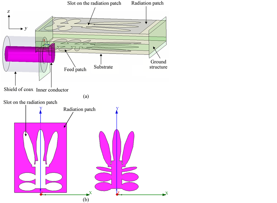
Figure 1. Configuration of the proposed antenna, (a) Overall view of the antenna, (b) Left: radiation patch, right: feed patch.
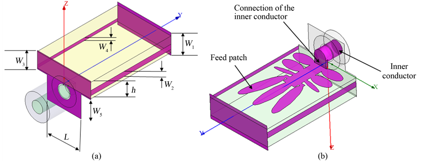
Figure 2. (a) Geometrical view and dimensional parameters of the ground structure; (b) Connection of the inner conductor.
This combination is chosen because of its wide impedance bandwidth and good radiation characteristics. The operating bandwidth and radiation patterns of the proposed QSCA critically depend on the dimensions and position of the ground structure. Moreover the ground structure determines the size of the antenna. As shown in Figure 2(b) the feed section of the designed antenna is divided into two parts: a 50 W coaxial probe and the feed patch. For the low return loss, the shield of the coaxial probe is connected to the end of the ground structure and its inner conductor is connected to the feed patch. A substrate of low dielectric constant is selected to obtain a compact radiating structure that meets the demanding bandwidth specification. The antenna is printed on an FR4 dielectric substrate with a relative permittivity εr = 4.4, a loss tangent δ = 0.02, and a thickness of h = 1.6 mm. The substrate size is selected as 6 mm × 9 mm, which is equal to 0.11 λ0 × 0.16 λ0, where, λ0 is the free space wavelength at the center frequency (5.3 GHz). Final optimum values of the geometrical parameters are as follows: W1 = 2.2 mm, W2 = 0.5 mm, W3 = 1.8 mm, W4 = 0.3 mm, W5 = 2.5 mm, and L = 3.8 mm. All of the dimensional parameters are optimized through extensive simulations and optimization via Ansoft HFSS and CST Microwave Studio software packages to provide the broadest impedance bandwidth along with good radiation characteristics. The main tradeoff issue in the design of the QSCA is size reduction and bandwidth enhancement of the antenna.
3. Results and Discussion
In this section, simulation results of the proposed QSCA are presented. To emphasize the accuracy of the simulated results, two commercially software packages, the Ansoft HFSS and CST Microwave Studio have been used. HFSS and CST are three-dimensional electromagnetic simulators based upon different computational techniques. HFSS is based on finite element method (FEM) which is more accurate for designing antennas while CST is based upon finite integral technique (FIT) and is also popular among antenna designers due to ease in simulations. Moreover, CST is a time-domain simulator but HFSS is a frequency-domain simulator. Both the simulator packages show very close results confirming that the simulated results are obtained with reasonable accuracy.
The simulated reflection coefficient of the designed antenna is presented in Figure 3. It can be seen that the proposed antenna has an operating bandwidth ranging from 4.5 to 6.1 GHz for S11 < −10 dB, which covers the two IEEE 802.11a WLAN bands (5.15 - 5.35 GHz and 5.725 - 5.825 GHz). The impedance bandwidth is limited by matching between the feed patch shape and the slot on the radiation patch. The desired impedance matching is obtained by enhancing the coupling between the radiation patch and feed patch. When the coupling is increased to a certain value, an optimum impedance bandwidth can be obtained. However, if the coupling is further increased more than this value, the impedance matching will deteriorate. By choosing suitable combination of feed path and slot shapes and tuning their dimensions, an optimum impedance bandwidth is obtained. Moreover, as mentioned before, the operating bandwidth of the proposed antenna is critically dependent on the dimensions and position of the ground structure.
Figure 4 presents the simulated co- and cross-polar far-field E-plane (x-z plane) and H-plane (y-z plane)
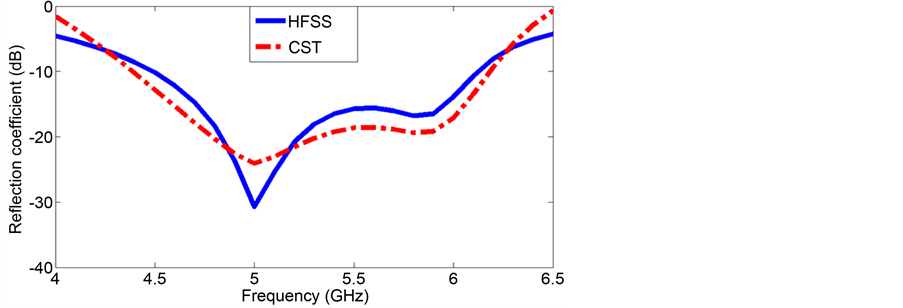
Figure 3. Simulated reflection coefficient of the proposed antenna, W1 = 2.2 mm, W2 = 0.5 mm, W3 = 1.8 mm, W4 = 0.3 mm, W5 = 2.5 mm, h = 1.6 mm, and L = 3.8 mm.
radiation patterns of the designed QSCA at several typical frequencies. As indicated in this figure, excellent omni-directional radiation patterns without ripple in the E-plane are obtained, confirming appropriate antenna performance in the whole desired frequency band. Furthermore, the radiation patterns show that the designed antenna provides linear polarization with cross polarization level at least 20 dB lower than the co-polarization level. The cross-polarization levels at other frequencies are also very small, indicating excellent polarization purity.
The magnitude of the surface current on the radiating patch and feed patch at the center frequency, 5.3 GHz, is presented in Figure 5. As shown in this figure, minimum magnitude of the surface current is occurred at the edges of the feed patch and the maximum magnitude of the surface current is occurred at the edges of the slot on the radiating patch. As before mentioned, the radiating patch is excited by the feed patch.
The realized gain of the proposed antenna versus frequency is shown in Figure 6. Good agreement between outcomes of both simulators is obtained. The curve in the figure suggests a considerable directivity compared to its electrical dimensions. In the band between 4.5 and 6.1 GHz, the minimum gain is at the frequency 4.5 GHz with a value 0.4 dBi and maximum gain is 1.9 dBi. The jitter behavior presented in the figure is possibly due to the irregular currents around the slot, especially at high frequencies.
One of the significant parameters in the broadband communication system design is the group delay between transmitting and receiving antennas, which shows the pulse distortion at the receiving antenna. To prevent the pulse distortion, the group delay must be constant. Figure 7 and Figure 8 show the simulated phase response
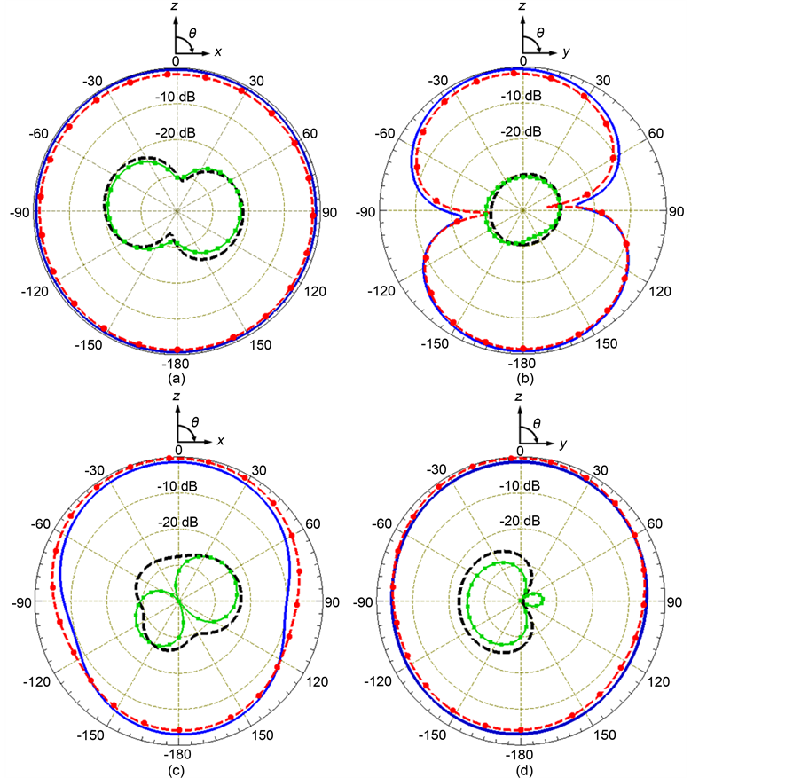

Figure 4. Radiation patterns of the proposed QSCA, (a) E-plane and (b) H-plane patterns at 4.5 GHz, (c) E-plane and (d) H-plane patterns at 5.3 GHz, and (e) E-plane and (f) H-plane patterns at 6.1 GHz.
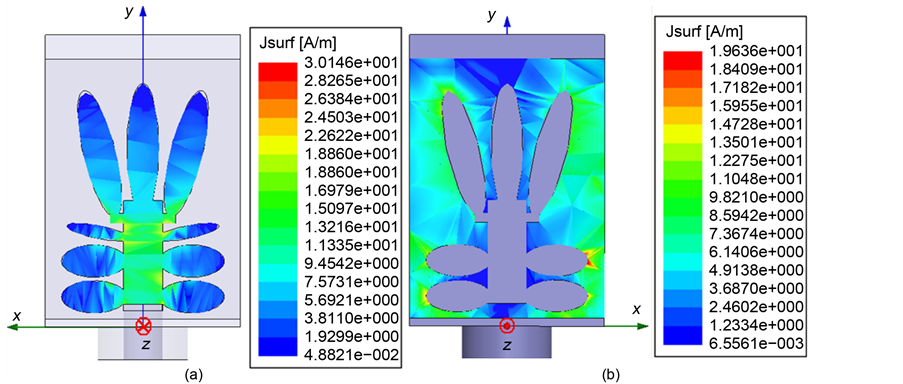
Figure 5. Magnitude of the surface current at the center frequency (5.3 GHz), (a) On the feed patch, (b) On the radiating patch.
and group delay characteristics of the designed antenna, respectively. As presented in Figure 7, the QSCA has a linear phase response. Furthermore, Figure 8 indicates that the variation of the group delay is less than 2 ns over the entire frequency range, showing proper dispersion performance of the designed antenna. In other words, the result indicates that this antenna is reliable so that a transmitted signal will not be seriously distorted by the proposed antenna.
Notice that a in the simulation results, a little difference is found between the outcomes of the two software packages. This is due to the different computational techniques of HFSS and CST. As was mentioned before, HFSS is based on FEM while CST is based upon FIT.
To conclude, the main tradeoff issue in the design of the QSCA is the size reduction of the antenna and antenna radiation characteristics such as the gain, operating bandwidth, and radiation patterns. Compared to the reported antenna in [12] , the proposed antenna features much smaller size and wider bandwidth. Also, in contrast
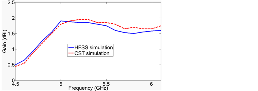
Figure 6. Realized gain of the proposed QSCA versus frequency.

Figure 7. Phase response of the QSCA obtained by HFSS.
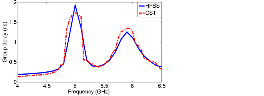
Figure 8. Group delay of the QSCA.
to the antenna presented in [13] , the proposed antenna has a smaller size as well as good far-field radiation patterns. According to the obtained results in both frequency and time domain, the proposed QSCA is especially suitable for utilize in wireless communication systems.
4. Sensitivity Analysis
A comprehensive numerical sensitivity analysis has been done to understand the effects of various dimensional parameters and to optimize the performance of the designed antenna. In this section, all of the simulations are performed using Ansoft HFSS. It is found through the simulations that the operating bandwidth of the proposed QSCA is critically sensitive to the dimensional parameters of the ground structure. These parameters are set as variables and their effects on the impedance bandwidth are studied. In order to achieve a wide bandwidth the above parameters are optimized.
Figure 9 shows the simulated reflection coefficient of the QSCA for various widths W1 while the other parameters of the antenna are kept fixed. It is seen that this parameter can affect the low frequency performance but the high frequency performance of the proposed antenna is almost independent of it. The best value for W1 in the designed antenna is 2.2 mm. The comparison of the simulated reflection coefficient versus the frequency for various widths W2 is presents in Figure 10. As shown in this figure, the reflection coefficient varies within the whole band as W2 changes. The optimal width of W2 is 0.5 mm. The simulated reflection coefficient versus the operating frequency for different widths W3 is plotted in Figure 11. It is obvious that W3 is an important parameter that influences the reflection coefficient. The optimum value of this parameter for maximum impedance bandwidth is 1.8 mm. The effect of the various widths W4 on the antenna performance is shown in Figure 12. It can be seen that this parameter affects the reflection coefficient of the proposed antenna most effectively.
5. Conclusion
This paper presents a new compact QSCA fed by a 50 W coaxial probe. The proposed antenna with a very small size of 6 mm × 9 mm has an operating impedance bandwidth of 4.5 to 6.1 GHz for S11 < −10 dB, which covers the two IEEE 802.11a WLAN bands (5.15 - 5.35 GHz and 5.725 - 5.825 GHz). The antenna does not provide

Figure 9. Simulated reflection coefficient of the QSCA for various W1, W2 = 0.5 mm, W3 = 1.8 mm, W4 = 0.3 mm, W5 = 2.5 mm, h = 1.6 mm, and L = 3.8 mm.
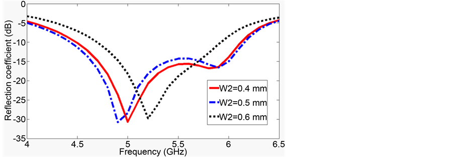
Figure 10. Simulated reflection coefficient of the QSCA for various W2, W1 = 2.2 mm, W3 = 1.8 mm, W4 = 0.3 mm, W5 = 2.5 mm, h = 1.6 mm, and L = 3.8 mm.
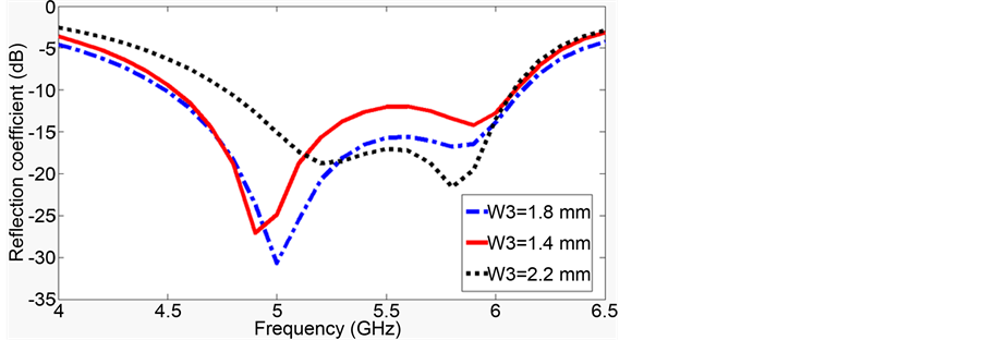
Figure 11. Simulated reflection coefficient of the QSCA for various W3, W1 = 2.2 mm, W2 = 0.5 mm, W4 = 0.3 mm, W5 = 2.5 mm, h = 1.6 mm, and L = 3.8 mm.
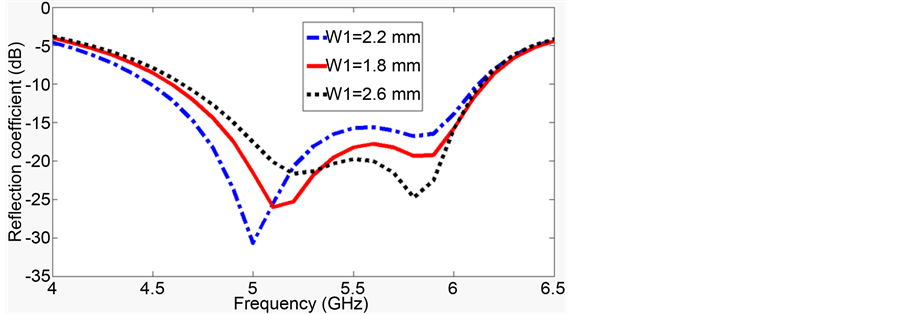
Figure 12. Simulated reflection coefficient of the QSCA for various W4, W1 = 2.2 mm, W2 = 0.5 mm, W3 = 1.8 mm, W5 = 2.5 mm, h = 1.6 mm, and L = 3.8 mm.
only a wide operating bandwidth, but also good omni-directional coverage with low cross polarization throughout the band. Moreover, the designed antenna has a linear phase response and almost constant group delay. A novel ground structure composed of five rectangular plates is proposed to enhance the impedance bandwidth and reduce the antenna size. The QSCA is comprised of two patches surrounded by the ground structure. Two metal patches of the antenna are located on two opposite sides of the dielectric substrate. By properly choosing the suitable feed patch shape, selecting similar slot shape on the radiation patch, and tuning their dimensions, optimum radiation characteristics are obtained. Besides, numerical sensitivity analysis shows that the radiation characteristics of the proposed antenna are extremely sensitive to the configuration and dimensional parameters of the ground structure. The designed antenna is simulated with Ansoft HFSS and CST Microwave Studio software packages. Both show very close results confirming that the simulated results are reasonably accurate. The obtained results in both frequency and time domain show that the proposed antenna is a good candidate for use in wireless communication systems.
Cite this paper
Aliakbar Dastranj, (2016) A New Compact Omni-Directional Quasi-Self-Complementary Antenna for Wireless Communication Systems. Open Journal of Antennas and Propagation,04,24-33. doi: 10.4236/ojapr.2016.42003
References
- 1. Han, T.Y., Sim, C.Y.D. and Lai, Y.N. (2014) Dual-Band Quasi-Self-Complementary Antenna for Wireless Local Network Operation. International Journal of RF and Microwave Computer-Aided Engineering, 24, 298-305. http://dx.doi.org/10.1002/mmce.20761
- 2. Haque, M., Mitra, D. and Ghosh, B. (2010) Miniaturized C-Slot Patch Antenna for Wireless Communication. International Conference on Signal Processing and Communications (SPCOM), Bangalore, 1-4. http://dx.doi.org/10.1109/spcom.2010.5560504
- 3. Denidni, T.A. and Rao, Q. (2006) Ultra-Wideband Slot Antenna for Wireless Communication Systems. International Journal of RF and Microwave Computer-Aided Engineering, 16, 408-413.
http://dx.doi.org/10.1002/mmce.20161 - 4. Nedil, M., Denidni, T.A. and Talbi, L. (2006) Wideband Slot Antenna Using a New Feeding Technique for Wireless Applications. International Journal of RF and Microwave Computer-Aided Engineering, 16, 125-134. http://dx.doi.org/10.1002/mmce.20117
- 5. Deschamps, G.A. (1959) Impedance Properties of Complementary Multiterminal Planar Structures. IRE Transaction on Antennas and Propagation, 7, 371-378. http://dx.doi.org/10.1109/TAP.1959.1144717
- 6. Mushiake, Y. (2004) A Report on Japanese Development of Antennas: From the Yagi-Uda Antenna to Self-Comple- mentary Antennas. IEEE Antennas and Propagation Magazine, 48, 47-60.
http://dx.doi.org/10.1109/MAP.2004.1373999 - 7. Mushiake, Y. (1992) Self-Complementary Antennas. IEEE Antennas and Propagation Magazine, 34, 23-29. http://dx.doi.org/10.1109/74.180638
- 8. Takemura, N. (2009) Inverted-FL Antenna with Self-Complementary Structure. IEEE Transaction on Antennas and Propagation, 57, 3029-3034. http://dx.doi.org/10.1109/TAP.2009.2028640
- 9. Abd El-Hameed, A.S., Salem, D.A., Abdallah, E.A. and Hashish, E.A. (2013) Fractal Quasi-Self Complimentary Miniaturized UWB Antenna. IEEE Antennas and Propagation Society International Symposium (APSURSI), Orlando, 15-16.
- 10. Wong, K.-L., Wu, T.-Y., Su, S.-W. and Lai, J.-W. (2003) Broadband Printed Quasi-Self-Complementary Antenna for 5.2/5.8 GHz WLAN Operation. Microwave and Optical Technology Letters, 39, 495-496.
http://dx.doi.org/10.1002/mop.11258 - 11. Xu, P., Fujimoto, K. and Lin, S. (2002) Performance of Quasu-Self-Complementary Antenna Using a Monoploe and a Slot. IEEE Antennas and Propagation Society International Symposium (APSURSI), San Antonio, 464-467.
- 12. Chang, L., Chien, H.-Y. and Lee, C.-H. (2012) Compact Dual-Band Quasi-Self Complementary Antenna for WLAN Application. International Symposium on Antennas and Propagation (ISAP), Nagoya, 1043-1046.
- 13. Abd El-Hameed, A.S., Salem, D.A., Abdallah, E.A. and Hashish, E.A. (2013) Notched Quasi Self-Complementary UWB Microstrip Antenna. IEEE Antennas and Propagation Society International Symposium (APSURSI), Orlando, 588-589. http://dx.doi.org/10.1109/aps.2013.6710954
- 14. Kuroki, F., Ohtal, H., Yamaguchi, M. and Suematsu, E. (2006) Wallhanging Type of Self-Complementary Spiral Patch Antenna for Indoor Reception of Digital Terrestrial Broadcasting. IEEE International Microwave Symposium Digest, San Francisco, 194-197.
- 15. Guo, L., Wang, S., Gao, Y., Wang, Z., Chen, X. and Parini, C.G. (2008) Study of Printed Quasi-Self-Complementary Antenna for Ultra-Wideband Systems. Electronic Letters, 44, 511-512.
http://dx.doi.org/10.1049/el:20083612 - 16. Guo, L., Wang, S., Gao, Y., Wang, Z., Chen, X. and Parini, C. (2008) A Miniature Quasi-Self-Complementary Antenna for UWB Applications. Asia-Pacific Microwave Conference, Macau, 1-4.
- 17. Huang, C.-Y. and Su, J.-Y. (2011) A Printed Band-Notched UWB Antenna Using Quasi-Self-Complementary Structure. IEEE Antennas and Wireless Propagation Letters, 10, 1151-1153.
http://dx.doi.org/10.1109/LAWP.2011.2172178 - 18. Lin, C.-C., Huang, C.-Y. and Su, J.-Y. (2011) Ultra-Wideband Quasi-Self-Complementary Antenna with Band-Rejec- tion Capability. IET Microwaves Antennas and Propagation, 5, 1613-1618.
http://dx.doi.org/10.1049/iet-map.2011.0043 - 19. Guo, L., Wang, S., Chen, X. and Parini, C. (2012) Miniature Ultra-Wideband Antenna for Wireless Universal Serial Bus Dongle Applications. IET Microwaves Antennas and Propagation, 6, 113-119.
http://dx.doi.org/10.1049/iet-map.2011.0023 - 20. Cortes-Medellin, G. (2011) Non-Planar Quasi-Self-Complementary Ultra-Wideband Feed Antenna. IEEE Transaction on Antennas and Propagation, 59, 1935-1944. http://dx.doi.org/10.1109/TAP.2011.2122226
- 21. Khan, M.M., Mobin, I., Palikaras, G. and Kallos, E. (2012) Study of a Small Printed Quasi-Self-Complementary Ultra Wideband Antenna for On-Body Applications. 4th Computer Science and Electronic Engineering Conference (CEEC), Colchester, 179-183.
- 22. Lin, C.-C., Huang, C.-Y. and Chen, G.-H. (2013) Obtuse Pie-Shaped Quasi-Self-Complementary Antenna for WLAN Applications. IEEE Antennas and Wireless Propagation Letters, 12, 353-355.
http://dx.doi.org/10.1109/LAWP.2013.2250242 - 23. Kumar, A., Jakhar, B. and Agrawae, P. (2014) Design and Analysis of CPW-Fed Quasi-Self-Complementary Pentagonal Antenna for Ultra-Wideband Systems. International Conference on Signal Propagation and Computer Technology (ICSPCT), Ajmer, 754-757.
http://dx.doi.org/10.1109/icspct.2014.6885003