Open Journal of Geology
Vol.05 No.03(2015), Article ID:54572,13 pages
10.4236/ojg.2015.53009
Analysis of Geomechanical Properties in Terms of Parametric Discontinuities on Stability of Tunnels Distinct Element Method (Case Study: Water Tunnel of Golab)
Ehsan Nouri Dehnoo1,2, Hoseyn Mirzeynali3*, Alireza Farrokhnia2
1Department of Geology, Alborz Science and Research Branch, Islamic Azad University, Alborz, Iran
2Department of Geology, Karaj Branch, Islamic Azad University, Karaj, Iran
3Jarf Kavan Kavir Aria Engineering Co., Tehran, Iran
Email: *farrokhnia@kiau.ac.ir
Copyright © 2015 by authors and Scientific Research Publishing Inc.
This work is licensed under the Creative Commons Attribution International License (CC BY).
http://creativecommons.org/licenses/by/4.0/


Received 9 February 2015; accepted 6 March 2015; published 12 March 2015
ABSTRACT
The discontinuities of the rock mass pose a high impact on its response to the static load and make complexity in modeling in such area. Principal objective of this study is to analyze the stability and sensitivity of Golab transfer tunnel access (transfer water from Zayanderud River to Kashan). This tunnel with a length of 5.1 kilometers and inclination of 13.5 percent is located 120 kilometers from Isfahan city. Geologically, this zone is in the range of sediment structure of Sanandaj-Sirjan. The host rock mass consists of Limestone Mesozoic (Cretaceous). The general characteristics of the joints in the rock represent high distance, low persistence, low opening (2 - 3 mm), average roughness and low weathering. Given purpose of the project and the distinct element method is the most useful for modeling rock mass for static analysis. This paper examines the effect of parametric factors on the stability of tunnels via UDEC software, discrete element and empirical method. After modeling, instability of Golab tunnel by increasing the depth is identified and confirmed. RMR, Q and GSI as experimental procedure were employed to classify the rock mass, based on RMR classification. The route rock mass has been taken in I and II categories and based on the Q classification, the path rock masses are recognized acceptable.
Keywords:
UDEC Software, Sakurai Equation, Sensitivity Analysis, Normal Stiffness, Shear Stiffness

1. Introduction
Till 1960s, planning and performing underground areas was based on experimental principles and the result was adjusted in the form of instructions and finally in 1970s, the result emerges in engineering classification. In 1976, the classification of rock engineering was presented by Bieniawski and Barton. From the 1960s with the progress in engineering science like the adhesive and non-adhesive area, analytical and theorical methods were flourished. Today, along with the advancement of technology and existence of various software for the stability analysis of tunnels perform with more accurate and faster in a short time. But this issue doesn’t reject the use of other methods particularly using experimental methods. But employing these methods with each other has desirable results. The methods which are used to evaluate and analyze the stability of underground spaces are classified in experimental, observational, analytical and numerical method. In this paper, some experimental and one numerical method jointly are used for the best result. In rock engineering problems, the existence of discontinuities in the rock mass as faults, discontinuities or layered surfaces poses a large influence on rock mass response to static and dynamic loads that cause complexity in modeling these environments. Cundall developed a DEM code, Universal Distinct Element Code (UDEC) to model the blocky rock systems [1] [2] . Cundall and Hart, 1992 review many of numerical techniques which have been developed to simulate the behavior of discontinuous systems. Distinct element methods (DEM) employ an explicit scheme to evolve the equations of motion of discrete bodies directly. Distinct element method (DEM) is one of the most appropriate methods for modeling of the rock mass static and dynamic analysis [3] .
UDEC divides the rock mass into discrete blocks. A discontinuity is represented in the model as a contact between the two blocks. The contact between each block is considered soft-contacts to solve the relative normal displacements at the block contacts [4] . The Distinct Element method (DEM) can directly approximate the block structure of the jointed rock using arbitrary polyhedra. Applying this approach, pre-existing joints are readily incorporated into the DEM model. By nature, the distinct element method can readily handle large deformation on the joints. Further, the method recognizes all new contacts between blocks resulting from relative block motion. With respect to the aim of present study, the sensitivity of the tunnel in the rock environment investigates due to the changes of the parametric factors. According to the mentioned features of application functionality of UDEC software, this software has been used in this research. Golab tunnel project was built to transfer water from Zayanderud River to Kashan. The project is approximately 11 kilometers including the main tunnel, access tunnel and underground pumping station. The main tunnel is dewatering by the reservoir structure is built near the Zayanderud regulation dam.
After covering 9 kilometers in main tunnel, water transfers to the pumping station and from there by pipeline installed in the access tunnel with the approximately 1.5 kilometers length is pumped to the refinery which is built at the entrance of the tunnel. Water is transmitted by pipelines to Kashan and crossing towns in the route. Loose and falling lands, rocks with many joints, faults cracked, weathered and made many problems when digging or widening the tunnel. Reducing the difficulties and costs depend on detailed geological engineering study about track, using the result of the investigation carried out an optimize design in which using a minimum of coverage and the strength of civil access an acceptable stability of the tunnel [5] . This research is discussed the stability evaluation of Golab tunnel access by using empirical rock mass classification (RMR), tunneling quality index (Q). This paper extends to determine the geological strength index (GSI) as well as using the distinct element method (UDEC software).
2. Study Area
According to the division of the range of Iranian sedimentary structure [6] the study area is located at sedimentary structure of Sanandaj-Sirjan at a distance of 50 Km from the Zagros fault and its structure process is parallel of the Zagros (125˚C - 135˚C). The host rock type of the access tunnel is the former of Cretaceous limestone which generally is shown that it is capable of being dissolved and made Karst aquifers in this sediment structure range then it is striking on based of Karst viewpoint.
3. Analysis of Tunnel Stability
Stability analysis methods are divided into four general methods. These methods include analytical method e.g. closed-form mathematical methods, experimental methods e.g. RMR, Q, and GSI, observational methods e.g. strain direct method and numerical methods. This paper is jointly used several experimental methods and a numerical method to sustain the Golab tunnel.
4. Empirical Methods
Most of the rock masses classification schemes (Bieniawski (1973, 1989), Barton et al. (1974) and Hoek et al. (1995)) were developed. Loose and falling lands, rocks with many of joints, faults cracked, weathered and dealt with some hard ships during digging and widening the tunnel. Reducing the difficulties and costs depend on the detailed geological engineering study about track, using the result of the investigation carried out an optimized design in which with using a minimum of coverage and the strength of civil access an acceptable stability of the tunnel.
All experimental methods are the most appropriate solution when the intended space is the best qualified because all these mentioned methods are the result of the collection and analysis of previous experience in underground spaces where were constructed. The results are applicable.
Thus, the scope of each method application should recognize that each classification should be used.
4.1. RMR Method
Bieniawski (1976) suggested the details of a rock mass classification called the Geomechanics Classification or the Rock Mass Rating (RMR) system. In the RMR classification method, superficial and shallow structures which are an average of three joints are often selected. In this method, the stress in the rock is under consideration and the structural conditions are governing the behavior of the rock mass. RMR of the rock mass classification system used six parameters, uniaxial compressive strength of rock material, Rock Quality Designation (RQD), Spacing of discontinuities, Condition of discontinuities, Groundwater conditions and Orientation of discontinuities [7] .
According to the given parameters, the calculation of RMR rating presents in (Table 1). In (Table 2), the parameters of rock mass resistance are calculated according to the basic rating. In (Table 3), the recommendations and implementation guidelines are located for the excavation and maintenance of the rock tunnel consistent with RMR.

Table 1. Required parameters to calculate RMR.
Table 2. Calculated points and resistance parameters of rock mass.
Table 3. Recommendations and implementation guidelines for excavation and maintenance of rock tunnel consistent with RMR (Bieniawski, 1989).
4.2. Q Method (Tunneling Quality Index)
Q categorized primarily has been developed to respond the questions which come up during building underground spaces and tunnels. Thus, after the calculation of Q and put it in the presented tables, inner strength which is necessary to keep the tunnel and underground space is obtained. Given parameters are required to determine Q (Table 4), where RQD is Rock Quality Designation, Jn is the joints sets number, Jr is the joints roughness number, Ja is the joints alteration number, Jw is the joint water reduction factor, SRF is the stress reduction factor and also used Equation (1) as a guide for the selection of temporary and permanent storage devices [8] .
4.3. GSI Method (Geological Strength Index)
The Geological Strength Index (GSI) is introduced by Hoek (1994). Hoek et al. (1995) and Hoek and Brown (1998) provide a system to estimate the reduction in rock mass strength for different geological conditions as identified by field observations. Geological strength index is determined by using 2 parameters: rock mass structure and discontinuity surface conditions. To determine the Geomechanical parameters of the mass of limestone, RocLab software v.1.0 was used which calculated the parameters based on GSI and the final standard presented by Hoek and Brown (1998) [9] [10] .
In the Figure 1 and Figure 2 respectively, the GSI and the calculated parameters of rock mass strength can be observed. There is a summary result of two methods of GSI and RMR in the (Table 5).
 (1)
(1)
5. Numerical Simulation
The water tunnel access Golab was analyzed using a universal distinct element code (UDEC). The DEM code was used for the analysis as the rock mass is jointed with three prominent sets of joints (Table 6).
The DEM enables us to gauge into the behavior of jointed rock mass, which is impossible in other numerical tools [11] . For modeling this project, a tunnel with a circular cross section with a radius of 2.65 m, with an average of 4 meters distance between joints and 200 meters length of amputations of joints and also the slope of 76 degree is considered.
After restricting the boundaries and determining the material which is limestone in this project, geometrical model was determined based on field discontinuities and information about the tunnel location in the rock mass. The Coulomb and Elastic slip models respectively were selected in order to defeat the critical joints and the blocks. The adhesion values and fiction joints degrees were determined from laboratory tests. In (Table 7), blocks properties (elastic model) and mechanical properties of rock material are presented. It should be noted that we used the 2 and 3 equations for determining normal and shear difficulty [12] . In 2 equation, Jkn is normal difficulty, Er and Em are respectively intact rock and rock mass elastic model and S is the whole spacing of discontinuities and in relation number Equation (3), Jks is shear stiffness, Gr and Gm is respectively the elastic model of original rock and rock mass and S is the whole spacing of discontinuities.
The defects of numerical modeling are excessive dependence on the input parameters that determine some of these parameters are difficult. Hence, it is recommended to use the numerical model to study about general behavior of the rock mass rather than acknowledge a certain amount at a certain point of the rock mass.
Table 4. Classification of individual parameters used in the Tunneling Quality Index Q.
Table 5. Summary result of two methods of GSI and RMR for cretaceous limestone mass.
Table 6. Joint orientation in rock mass.
Table 7. Block properties (elastic model) and mechanical properties of aggregate.
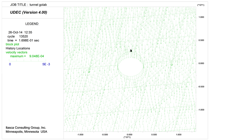
Figure 1. UDEC plot for the 150 meters depicting the velocity vectors.

Figure 2. UDEC plot for the 150 meters depicting the displacement contours.
 (2)
(2)
![]() (3)
(3)
Static Analysis
The tunnel Golab was analyzed using a universal distinct element code (UDEC). The DEM code was used for the analysis as the rock mass is jointed with three sets of joints. Static analysis was conducted with static boundary conditions apply (fixed boundaries, vertical and lateral gradient stress with assumption of the ratio of lateral to vertical stress). After establishing the condition of static equilibrium, the tunnel is excavated. The results show that the structure system is reached to equilibrium and the lack of primary care system for excavation. For stability analysis and preliminary maintenance system design of tunnel, numerical distinct element method is used which has been developed by Cundall in 1971 to solve the problems of rock mechanics in jointed rock masses. In this method, the rock mass is assumed as a series of separate blocks that posed an effective interaction in the edge and corners and the joints are considered as common border of blocks (Hoek et al., 1995). Initially, it is necessary to make the model stable from static viewpoint, then we can analyze the model statically with the change in parametric factors, but it is possible just in a case of removing the dynamic pressure from tunnel. For this purpose, the blocks are designed under the term of gravity loading. The left, right and inferior boundaries are fixed. A control point also exists at the height of 2.65 from the center of tunnel. A maximum of velocity vector of 9.102 × 10⁴ m/s while a maximum of displacement of −1.25 × 10⁻³ m was developed for the depth of 150 meters (Figure 1 and Figure 2).
The maximum of vertical displacement from 50 meters to 150 meters was estimated (Figures 3-7).
For the depth of 150 meters, the model took 7570 cycles in 4.149 e−1 seconds to attain the equilibrium condition of almost zero unbalanced force (Figure 8). Some movements occur in the tunnel ceiling and walls. Therefore, falling and sliding of blocks is likely in this area.
One of the methods can be used to reveal the area which downfall appears around the section of tunnel or tunnel’s stability is identified the areas in which the plastic is made around the tunnel. Plastic zones occurred in the tunnel estimated (Figures 9-13). After the modeling, estimate there is plastic in some areas above the tunnel crown and the walls at a depth of 50 meters Figure 9. With increasing the depth, the amount of plastic has been grown insofar the red points, down fall areas appear around the tunnel section in 150 meters. (Figure 13). In other words, the loss is located more in the left wall and some areas of the right wall. The following Sakurai and factor of safety procedure methods are used to determine whether the loss of those areas can affect the stability or instability of the tunnel.
![]()
Figure 3. Vertical displacement at the depth of 50 meters.
![]()
Figure 4. Vertical displacement at the depth of 75 meters.
![]()
Figure 5. Vertical displacement at the depth of 100 meters.
![]()
Figure 6. Vertical displacement at the depth of 125 meters.
![]()
Figure 7. Vertical displacement at the depth of 150 meters.
![]()
Figure 8. Unbalanced force vs. cycle plot for the depth of 150 meters.
![]()
Figure 9. Plastic zone established around the tunnel at the depth 50 meters.
![]()
Figure 10. Plastic zone established around the tunnel at the depth 75 meters.
![]()
Figure 11. Plastic zone established around the tunnel at the depth 100 meters.

Figure 12. Plastic zone established around the tunnel at the depth 125 meters.

Figure 13. Plastic zone established around the tunnel at the depth 150 meters.
The critical strain (authority) is one of the ways by which can be considered to measure the displacement of the tunnels like subsidence crown and convergence which is always smaller than the failure strain. Sakura relating the laboratory Results and field data were obtained a relationship between the critical strain and compressive strength and Young’s modulus and three levels warning of the danger presented as follows [13] :
 (4)
(4)
 (5)
(5)
 (6)
(6)
Danger Warning level I and III are licensed as both upper and lower limit for tunnels stability based on the allowable strain. In other words, danger warning we have shown long term stability and in this situation the tunnel doesn’t have instability problem and danger warning III shows short-term stability. Sakura has proposed the risk warning level II as the basis of the tunnels design. Allowable displacement is determined by determining critical strain and Equation (7).
 (7)
(7)
In this regard, Uc is allowed movement for the created model,  is critical strain in percentage and it is the tunnel radius in meters. Numerical modeling is used to check the displacements were carried out at various depths. Strain curves and modeled displacement in this depth and finally calculated displacement and safety ration is presented in (Table 8) which is the result of numerical modeling. After calculating the critical strain with use of Equation (8), we can calculate the safety ratio in any depth which is based on the following equation [14] :
 (8)
(8)
Finally considering the radius of the underground structure (2.65 meters), the permitted movement is:

Then, the maximum rate of changes for the stability of the wall of the underground structure which is calculated by numerical analysis should not be more than 1.06 centimeters.
According to Sakurai relation, summarizing the results of numerical modeling also obtained allowable strain rate and allowable displacement from this equation which was prepared in the following table [8] . Given in the depth of 150 meters, the allowable displacement calculated is lower than the allowable displacement as well as the safety factor which is greater than 1, the Golab access tunnel is not face with the instability problem.
6. Conclusion
Stability of Golab access tunnel was analyzed using empirical methods and DEM code for 50 meters to 150 meters using the coulomb constitutive model. The host rock masses of Golab access tunnel are in category (II) of the RMR classification which grade the limestone rock mass based on their joint’s general properties. The host rock mass classification in Golab access tunnel based on Q classification is placed in the appropriate category. Based on the numerical modeling and UDEC software and based on the Sakurai relation and factor of safety de-
Table 8. Relocation allowance calculated at depths of 50 to 150 meters.
termined that depth increasing enhanced plastic state and stone submission and also emerges break in the wall of the left and some parts of the right wall cause some loss in the tunnel but because it does not expand, the tunnel does not face the instability problem. Hence, the tunnel is stable at all depths.
Acknowledgements
The authors would like to thank Dr. Azadeh Mehrpouyan for her insightful comments on an earlier draft of this article and done proofreading on it.
References
- Cundall, P.A. (1971) A Computer Model for Simulating Progressive Large Scale Movements in Blocky Rock System. International Proceedings Symposium, 128-132.
- Cundall, P.A. (1980) UDEC: A Generalized Distinct Element Program for Modelling Jointed Rock. Report PCAR-I-80, Peter Cundall Associates Report, European Research Office, US Army, Contract, DAJA37-79-C-0548.
- Itasca Consulting Group Inc. (1992) UDEC Universal Distinct Element Method. Users Manual, Version 1.18.
- Nichol, S., Hungr, O. and Evans, S. (2002) Large-Scale Brittle and Ductile Toppling of Rock Slopes. Canadian Geo- technical Journal, 39, 773-788. http://dx.doi.org/10.1139/t02-027
- Consultants Rey Water Consulting Engineers (2005) Engineering Report.
- Aghanabati, A. (2005) Iran Geology. Mineral Exploration Geological Publishing.
- Bieniawski, Z.T. (1976) Rock Mass Classification in Rock Engineering. In: Bieniawski, Z.T., Ed., Symposium Proceedings of Exploration for Rock Engineering, 1, 97-106.
- Barton, N.R., Lien, R. and Lunde, J. (1974) Engineering Classification of Rock Masses for the Design of Tunnel Support. Rock Mechanics, 6, 189-239. http://dx.doi.org/10.1007/BF01239496
- Hoek, E., Kaiser, P.K. and Bawden, W.F. (1995) Support of Underground Excavation in Hard Rock. Balkema, Rotterdam.
- Hoek, E. and Brown, E.T. (1998) Practical Estimates of Rock Mass Strength. International Journal of Rock Mechanics and Mining Science, 34, 1165-1186. http://dx.doi.org/10.1016/S1365-1609(97)80069-X
- Aglawe, J.P. and Corkum, A.G. (2006) Application of Distinct Element Analysis in Slope Stability Problems. Indo-Norwegian Workshop on Seismic Hazard and Risk Assessment, New Delhi.
- Itasca Consulting Group, Inc. (2000) UDEC, Universal Distinct Element Code. Version 3.1, User’s Manual.
- Sakurai, S. (1997) Lessons Learned from Field Measurement in Tunneling. Tunneling and Underground Space Technology, 12, 453-460.
- Sakurai, S. (1997) Lessons Learned from Field Measurement in Tunneling. Tunnelling and Underground Space Technology, 12, 453-460. http://dx.doi.org/10.1016/S0886-7798(98)00004-2
NOTES

*Corresponding author.