Optics and Photonics Journal
Vol.3 No.5A(2013), Article ID:36992,6 pages DOI:10.4236/opj.2013.35A002
Raman Microspectroscopy as a Unique Method of the Investigation of Acid Proof Steel Foil Oxidation
1Faculty of Chemistry, Jagiellonian University, Kraków, Poland
2Jerzy Haber Institute of Catalysis and Surface Chemistry, Polish Academy of Sciences, Kraków, Poland
3Institute of Metallurgy and Materials Science Polish Academy of Sciences, Cracow, Poland
Email: *mnajbar@chemia.uj.edu.pl
Copyright © 2013 A. Wesełucha-Birczyńska et al. This is an open access article distributed under the Creative Commons Attribution License, which permits unrestricted use, distribution, and reproduction in any medium, provided the original work is properly cited.
Received May 21, 2013; revised June 25, 2013; accepted July 23, 2013
Keywords: 1H18N9T Steel Foil; Oxidation; Raman Microspectroscopy; Morphology; Phases
ABSTRACT
In this paper, the results of the investigation of the morphology and phase composition of the oxide layers formed on the surface of the 1H18N9T acid proof steel foil by confocal Raman micro-spectroscopy with optical microscopy, SEM, XRD and TEM-EDS-SADP are presented. The foil oxidation was performed by thermo-programmed heating up to 823, 1023 or 1113 K and next annealing at the final temperatures in the air flow for 48 h, 4 h and 4 h, respectively. The great advantages of the use of the Raman spectroscopy for the phase determining in the oxide layers on the acid proof steel foil are shown. Moreover the possibility of applying the optical microscopy for investigation of the surface morphology of both the initial steel foil and the oxide layers is pointed out.
1. Introduction
Monolithic catalysts are commonly used for air pollution abatement. At the beginning, they were produced with the use of ceramic monoliths. Nowadays the metallic monolithic three-way catalysts, for NOx, CO, and HC removal from spark engine exhaust, become competitive to the ceramic ones. The oxidation of the fecralloy (Fe, Cr, Al, Y) or kantal (Fe, Cr, Al, Co) steel foils results in the formation of adhesive alumina layers [1].
Recently our interest is focused on oxidation of the metallic monoliths manufactured from the 1H18N9T acid proof steel foil [2]. The spinel phases and Me2O3 type oxides are formed on channel walls of those monoliths during the oxidation. These phases show good activity in the NO decomposition [3] in the carbon particle presence, thus, they could be used as environmental catalysts for nitrogen oxides removal from off gases of fossil fuel combustors.
The morphology, as well as chemical and phase composition of the surface layers of the oxidized monolith channels, strongly depends on the oxidation temperature [2].
The knowledge of the influence of the conditions of the oxidation on phase composition and morphology of the oxide layers is very important for designing the procedure of the monolithic catalyst production [2,3].
In the present paper, the possibilities of the use of the Raman microspectroscopy with optical microscopy for determination of the morphology and the phase composition of the oxide layers are tested.
The optical microscopic images of the foil surface are compared with secondary electron (SE) images obtained in the scanning electron microscope (SEM).
The Raman spectra of the oxide layers are compared with X-ray diffraction (XRD) patterns and with selected area diffraction patterns (SADP) combined with the results of energy dispersive spectrometry (EDS) obtained in analytical transmission electron microscope (ATEM).
2. Experimental
2.1. 1H18N9T Acid Proof Steel Foil Oxidation
The foil oxidation was accomplished during thermoprogrammed (3 K·min−1) foil heating up to the temperatures: 823 K, 1023 K or 1123 K in the air flow (90 cm3·min−1) followed by an annealing at those temperatures for 48 h, and 4 h, respectively.
2.2. Raman Microspectroscopy with Optical Microscopy
The Oxide phases obtained on the 1H18N9T acid proof steel foils were excited with 785 nm line of the HP NIR diode laser (grating 1200 g/mm) and investigated with Renishaw InVia Raman spectrometer working in confocal mode in a backscattered geometry. A Leica microscope with 50x magnification objective was used to focus a laser on a samples (NA = 0.50). The laser power (~1 mW) was kept enough low to avoid phase modifications within oxide layers. The laser light was focused on the chosen points of the optical image.
2.3. Scanning Electron Microscopy
A SEM JEOL JSM-7500F with INCA Oxford Instrument EDX system was used to investigate the morphology of the surface of the initial and oxidized foils.
2.4. X-Ray Diffraction
An X’pert PRO MPD diffractometer with 2-d detector PIXCEL and the Bragg-Brentano reflection geometry was used to determine the phases present in the metallic foil and in oxide layers.
2.5. Transmission Electron Microscopy
An analytical transmission electron microscope (ATEM) FEI Tecnai G2 at 200 kV equipped with energy dispersive X-ray (EDX) detector was used to take a microscopic images selected area diffraction patterns (SADP) and chemical analysis of the chosen crystallites transparent for electrons. In order to prepare TEM samples, the oxide layer was scraped from foil and then the thin slices of it were placed on a carbon support copper grid.
3. Results
In Figure 1 the optical images of the initial foil (a) as well as of the foil oxidized up to 823 K (b), 1023 K (c) and 1113 K (d) are presented. In the optical image of the initial foil the metalic grains boundaries are well seen. In the image of the foil oxidised up to 823 K the areas with the colors changing from light brown to blue with the dimensions much greater than those of the metalic grains occur. The dimensions of the oxide areas formed during the oxidation up to 1023 K are similar to the dimensions of the steel grains. Finally, the oxide areas seen in the optical image of the foil oxidised up to 1113 K are of the order of magnitude smaller that these of the foil grains.
The SEM images of the of the initial foil (a) as well as of the foil oxidized up to 823 K (b), 1023 K (c) and 1113 K (d) (magnification 10,000×) are presented in Figure 2. In the secondary electron images (SEI) of the initial foil and of the foil oxidised up to 823 K steel grain boundaries are hardly seen. In the SEI of the foil oxidised up to 823 K small particles (possibly crystallites) of the average dimensions of 0.2 μm, inhomogeneusly distributed over the surfce, are visible. The oxide crystallites formed in the course of the foil oxidation up to 1023 K of average diameters of 0.7 μm strictly cover the surface of the metallic grains. However, the crystallites formed during the oxidation to 1113 K of the dimensions ca 1 μm are

Figure 1. Optical images of: initial 1H18N9T steel foil (a); foil oxidized up to 823 K (b); foil oxidized up to 1023 K (c); and foil oxidized up to 1113 K (d).
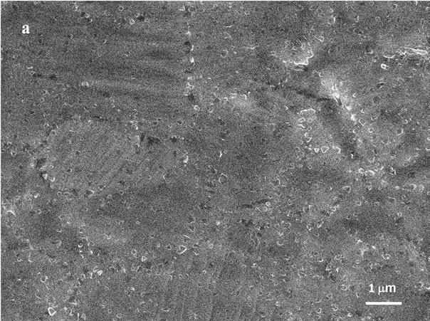
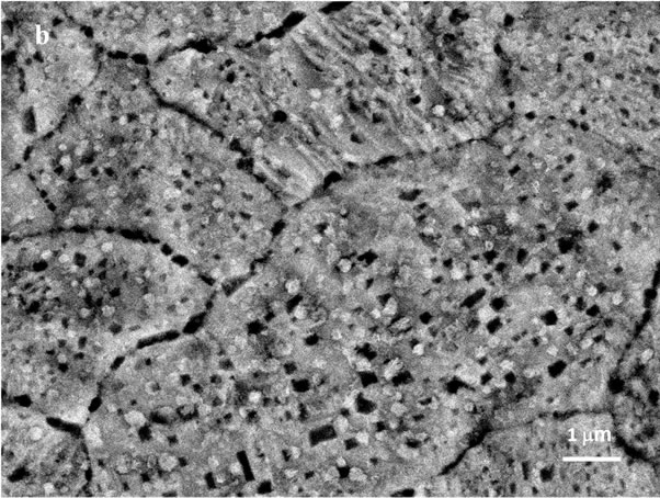
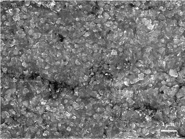
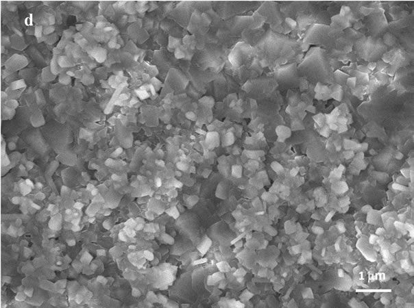
Figure 2. SEM images (10,000×) of: initial 1H18N9T steel foil (a); foil oxidized up to 823 K (b); foil oxidized up to 1023 K (c); and foil oxidized up to 1113 K (d).
separated and spread homogeneously over the whole foil surface. This particular crystallites correspond to the spots in the Figure 1(d).
The special attention should be paid to the comparison of the Figures 1(b) and 2(b). The color differentiation in the Figure 1(b) may be caused by inhomogeneous phase distribution or by differences in thickness of the oxide layer in particular areas. The Raman spectral mapping of that foil was performed to elucidate this problem.
In Figure 3 the points of the confocal spectral analysis were marked on the optical image of the surface foil. The points were chosen on the image areas of different color: 1and 3—yellow; 2 and 4—blue; and 5—brown.
In Figure 4, the spectra from the areas marked by the spots are presented.
Comparison of the spectra taken from the areas marked by 1 - 5 spots allows to find that all of them contain mainly peaks from hematite (295, 415, 228, 500, and 1330 cm−1) [4,5] and magnetite (657 cm−1) [5,6].
The intensive peak at 616 cm−1 being superposition of the main peak of manganese ferrite at 627 cm−1 [7] and the weak peak of hematite at 610 cm−1 [4,5] shows the
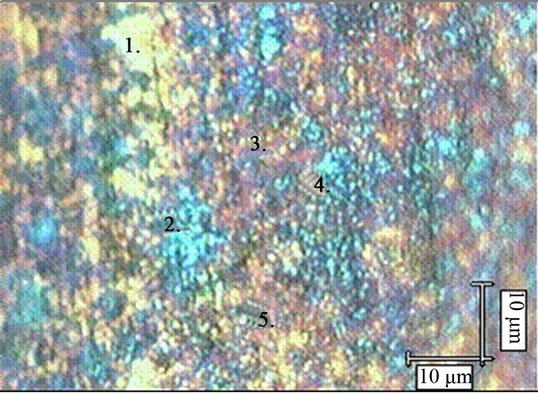
Figure 3. Optical image of the surface of the 1H18N9T steel foil oxidized up to 823 K with marked spots of the Raman mapping.
presence of manganese ferrite in all the analysed areas. It can be, thus thought that differentiation of the colors did do not arise from the differences in the phase distribution but rather from the differences in the thickness of the oxide layer in particular areas. Such thickness difference may be caused by different steel grain orientations.
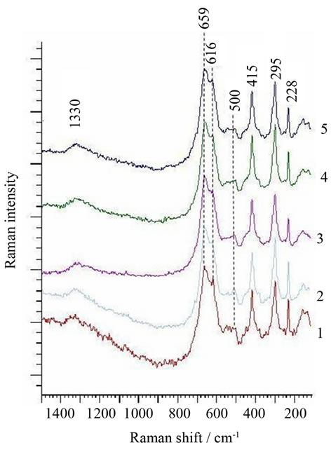
Figure 4. Raman spectra from the spots 1, 2, 3, 4 and 5 in the optical image (Figure 3) of the surface of the foil oxidized up to 823 K.
One can thus claim that optical microscopy and SEM may be considered as complementary methods for determining the morphology of the oxide layers on the acid proof steel foil.
The optical pictures give reliable information about the dimensions of the steel grains and allow to estimate influence of their orientations on the thickness the oxide layer. On the other hand, SEM is a unique method to follow crystals growth in the oxide layers.
The Raman spectra of the oxide phases formed during the foil oxidation up to 823 K, 1023 K and 1123 K followed by the annealing at the final temperatures are presented in Figure 5. The peak at 686 cm−1 is the basic peak of the manganese chromite [8] and this at 553 cm−1 is representative for hexagonal Cr2O3 [4]. Thus, we can claim that hematite, magnetite and manganese ferrite are the main phases in the oxide layer formed at 823 K. Hematite is the minor phase and the spinel phases dominate in the oxide layer formed in the course of the oxidation up to 1023 K. The shift of the position of the representative peak of magnetite towards higher wave number with respect to that in the spectrum of the oxide layer formed during the oxidation up to 823 K may be ascribed to the contribution of the main peak from manganese chromite or to the cationic substitution in magnetite.
Manganese chromite, MnCr2O4, manganese ferrite, MnFe2O4, and dichromium trioxide, Cr2O3, dominate in the oxide layer formed in the course of the oxidation up to 1113 K.
In Figure 6 and Table 1, XRD pattern of the foil oxi-
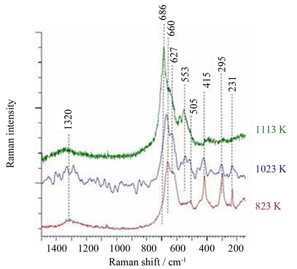
Figure 5. Raman spectra of the oxide layer formed on acid proof steel foil during thermoprogrammed (3 K·min−1) heating up to 823 K, 1023 K or 1113 K, followed by annealing at those temperatures in the air flow, for 48 h, 4 h and 4 h, respectively.
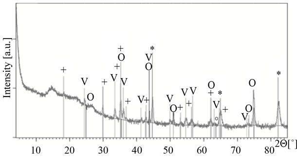
Figure 6. XRD pattern of the foil oxidized up to 1113 K and the results of qualitative and semi-quantitative phase analysis.
dized up to 1113 K is presented. Relatively high level of background may be caused by the form of the investigated sample; a metal foil covered with thin layer of oxides.
The peaks of the hexagonal Me2O3 phase are well distinguishable (Me = Fe, Cr) although the peaks of the Fe-Cr metallic phase are much more intensive. The spinel phase identification is more difficult due to the overlapping of some oxide reflections with reflection of metallic phases (at 2Θ = ca 35.3˚, 42.7˚, 43.7˚, 62.2˚ and 65˚). Moreover, very close lattice parameters of iron chromite, manganese chromites and manganese ferrite make impossible differentiation of those spinel phases. As the crystallites of the thin oxide layer formed on the foil oxidized up to 823 and 1023 K are relatively small and of low quantity their reflections in XRD patterns are too weak and some of them overlap with the metallic
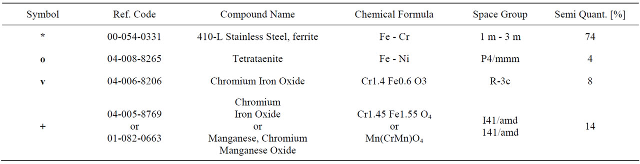
Table 1. XRD pattern of the foil oxidized up to 1113 K and the results of qualitative and semi-quantitative phase analysis.
phases reflections. Thus, the reliable phase identification is rather impossible.
Since Raman spectroscopy is limited to the oxide phases the problem of the overlapping of the spinel peaks with metal peaks does not exist and the peak from spinel phase in the oxides formed in the course of the oxidation up to 1113 K can precisely be ascribed to the manganese chromite.
In Figure 7, the TEM microstructure of the particle of the size about 100 nm, containing mainly Cr, Mn and small amount of Fe is shown (the results of EDX microanalysis were inserted).
Corresponding SADP allow to identify these crystallites as MnCr2O4 spinel. The results of the EDX microanalysis distinctly confirm cationic substitution of Fe for Cr.
However, to prepare the sample for TEM investigation the oxides should be first scratched from the foil, next grounded in the mortar and then placed on the carbon film laying on the copper grid. At last the obtained SADP have to be indexed.
4. Summary
In the presented paper, the possibility of the use of the Raman microspectroscopy with optical microscopy for determination of the morphology and the phase composition of the oxide layers formed during foil oxidation in the air flow is tested.
The comparison of the optical and secondary electron images allows to state that optical microscopy and SEM are complementary methods for determining the morphology of the surface of the oxide layers formed on the acid proof steel foil. The optical images give the reliable information about the dimensions of the steel grains and allow to estimate the influence of their orientations on the oxide layer thickness.
On the other hand, SE images allow to observe crystals growth in the oxide layers.
The comparison of the Raman spectra of the oxide layers with X-ray diffraction patterns and with electron selected area diffraction patterns shows that the confocal

Figure 7. TEM bright field image of chosen crystallite of the oxide layer formed during oxidation up to 1113 K (EDX result in at.% is inserted) and corresponding SADP.
Raman microspectroscopy is a unique non-destructive method for the phase identification in the oxide layers on the metallic foil.
5. Acknowledgements
The authors acknowledge the financial support by the European Regional Development Fund under the Innovate Economy Operational Program 2007-2013, POIG. 01.01.02-12-112/09 project.
REFERENCES
- J Camra, E. Bielańska, A. Bernasik, K. Kowalski, M. Zimowska, A. Białas and M. Najbar, “Role of Al Segregation and High Affinity to Oxygen in Formation of Adhesive Alumina Layers on FeCr Alloy Support,” Catalysis Today, Vol. 105, No. 3-4, 2005, pp. 629-633. doi:10.1016/j.cattod.2005.06.015
- E. Bielańska, J. Camra, J. Dutkiewicz, P. Kornelak, M. Najbar, A. Wesełucha-Birczyńska and T. Wilkosz, “Oxidation of Acid-Proof Steel Foil as a Method of Deposition of Phases Active in Nitrogen Oxides Decomposition on Metallic Monolith Walls,” Advanced Materials Research, Vol. 651, 2013, pp. 317-320. doi:10.4028/www.scientific.net/AMR.651.317
- J. Dutkiewicz, S. Janiga, I. Nazarczuk, M. Kozicki, P. Kornelak and M. Najbar, “Effect of Soot on NO Decomposition in O2 and SO2 Presence over Ni-Cr-Fe Oxide Catalysts,” Proceeding of the International Symposium on Nitrogen Oxides Emission Abatement, Zakopane, 4-7 September 2011, pp. 137-138.
- I. R. Beattie and T. R. Gilson, “The Single-Crystal Raman Spectra of Nearly Opaque Materials. Iron(III) Oxide and Chromium(III) Oxide,” Journal of the Chemical Society (A), 1970, pp. 980-986.
- D. L. A. de Faria, S. V. Silva and M. T. de Oliveira, “Raman Microspectroscopy of Some Iron Oxides and Oxyhydroxides,” Journal of Raman Spectroscopy, Vol. 28, No. 11, 1997, pp. 873-878. doi:10.1002/(SICI)1097-4555(199711)28:11<873::AID-JRS177>3.0.CO;2-B
- O. N. Shebanova and P. Lazor, “Raman Spectroscopic Study of Magnetite (FeFe2O4): A New Assignment for the Vibrational Spectrum,” Journal of Solid State Chemistry, Vol. 174, No. 2, 2003, pp. 424-430. doi:10.1016/S0022-4596(03)00294-9
- R. T. Downs, “The RRUFF Project: An Integrated Study of the Chemistry, Crystallography, Raman and Infrared Spectroscopy of Minerals,” Proceedings of the 19th General Meeting of the International Mineralogical Association, Kobe, 23-28 July 2006, pp. 3-13.
- Y. Chen, Z. Liu, S. P. Ringer, Z. Tong, X. Cui and Y. Chen, “Selective Oxidation Synthesis of MnCr2O4 Spinel Nanowires from Commercial Stainless Steel Foil,” Crystal Growth & Design, Vol. 7, No. 11, 2007, pp. 2279- 2281. doi:10.1021/cg070514a
NOTES
*Corresponding author.